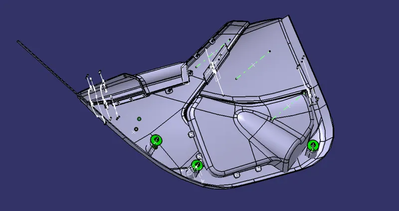
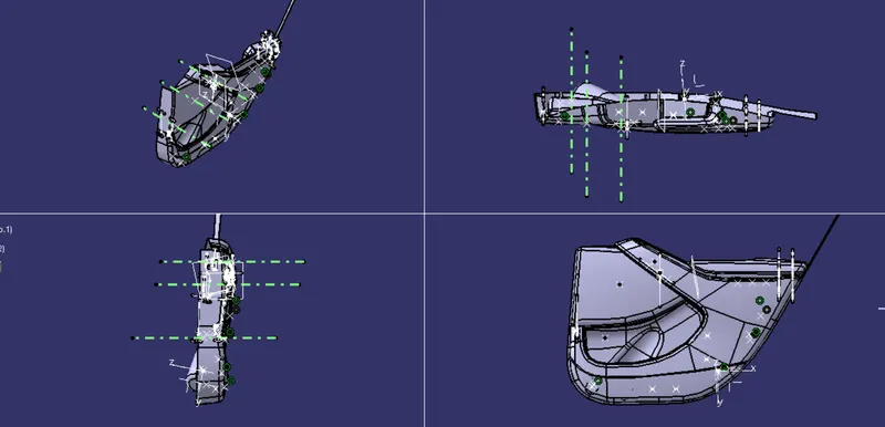
Catia - Final project
AIM
Development of door trim using CATIA from the given class A and master sections, and performing draft analysis on each part along with the creation of B side attachment features.
THEORIES AND CONCEPTS
RIBS
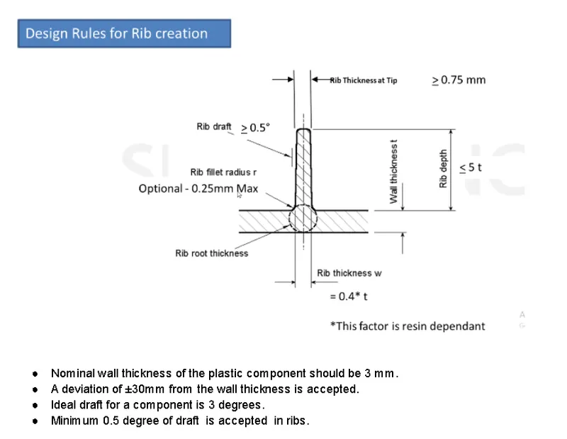
Design Rule for space between ribs.
Ribs should be spaced so that the steel between the ribs is at a height : width ratio of 3:1 for steel , 2:1 is preferred.
|
wall stock (mm) |
Max Rib thickness at base at 40% (mm) |
Min Rib thickness at tip (mm) |
Min draft (degree) |
Max rib height (mm) |
|
2.5 |
1 |
0.75 |
0.5 |
14 |
|
3 |
1.2 |
0.75 |
0.5 |
25 |
LOCATORS
By using locators , we can arrest the movements of a part in 3D space. Locators are of two types.
- 4 way locator.
This helps to arrest 4 degrees of freedom along 2 axes
- 2 way locator.
This helps to arrest 2 degrees of freedom along an axis.
HEAT STAKES
The process used for the joining of thermoplastic materials with dissimilar materials such as metal , plastic or other materials is called heat staking.
Heat/Thermal staking is an assembly process achieved by controlled melting and reforming of plastic studs or boss to lock another plastic or metal component onto a part. The protruding studs get locked in place and as they get in contact with the heated thermal tips , the stud melts and fills the volume of the tip cavity to lock itself in place.
Screw bose and dog house design
SCREW BOSE
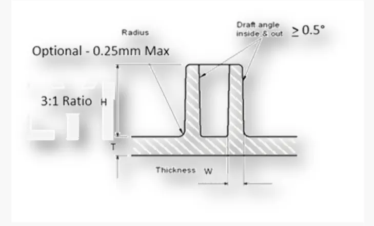
Screw bose attachment is used for holding the screw with the model or locating the fixing position of the screws.
Design guidelines for screw bosses.
Draft - 0.5 deg on walls of boss
Thickness- typically 40% of the nominal wall at the base.
Height to diameter ratio - 3:1
Radii - 0.25mm
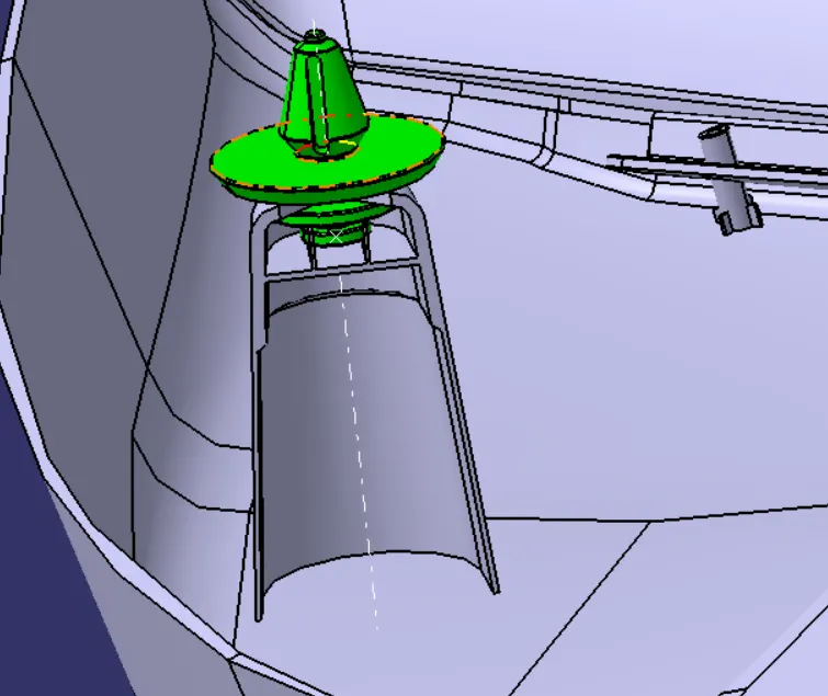
DOG HOUSE
Dog houses are used to prevent defects like shrinkage and breakages and also act as a guide.
Design guidelines for Dog house
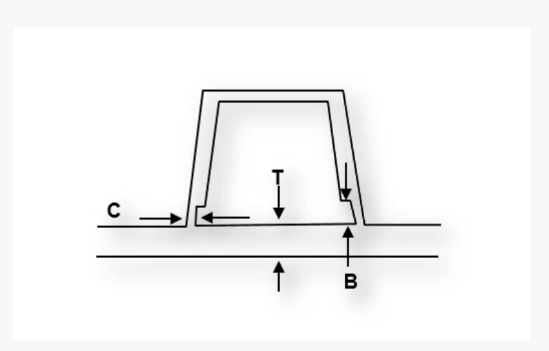
Dog House wall thickness at the intersection of the part wall ( c )should be 40% or less than the main wall stok ( T ).
Height of (B) should be between 3.0 - 6.0 mm
PROCEDURE
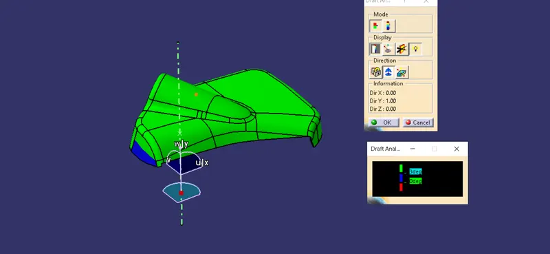
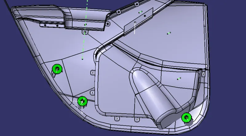
The b surface is offsetted from the given class a surface and by using sweep command the c surface is created by joining the class a, b and c the thickened part is created . This procedure is carried out map pocket 1 & 2, lower substrate and arm rest. Then perform draft analysis on individual parts. Create the flanges on map pockets , armrest and lower substrate , and add heat stakes to it. Also create a dog house and push pins then assemble it with the lower substrate.
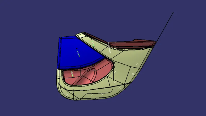
B SURFACE
B surfaces of all the parts are offsetted from the class A surface with a disatance of 2mm.
MAP POCKET
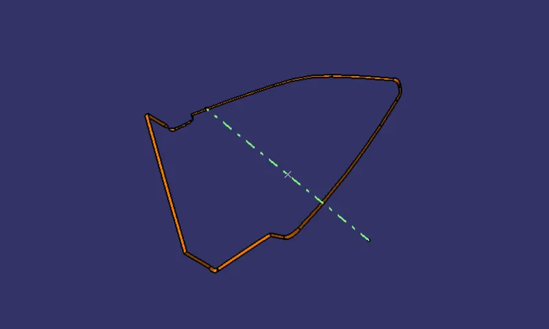
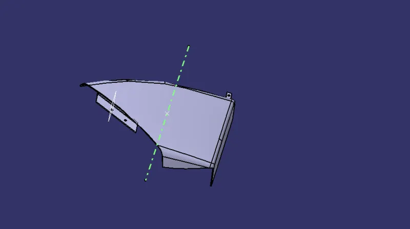
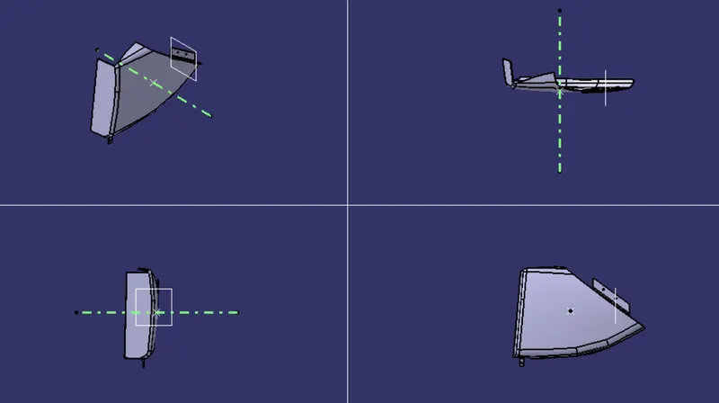
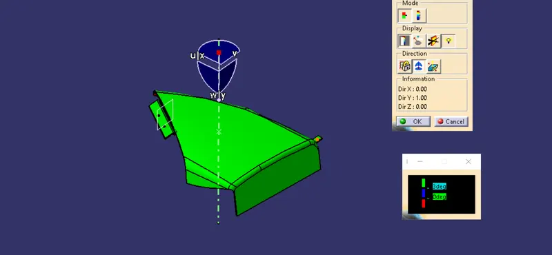
The C surface is made by sweeping the class A boundary as reference and then joining it with the class A and class B surface , a close surface is obtained . Thicken it to get a part body.
MAP POCKET 2
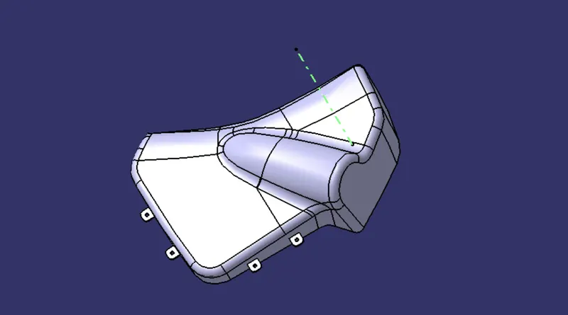
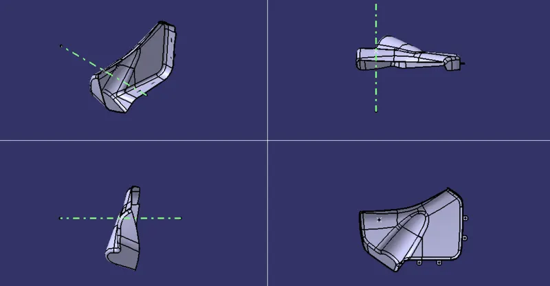
The C surface is made by sweeping the class A boundary as reference and then joining it with the class A and class B surface , a close surface is obtained . Thicken it to get a part body.
LOWER SUBSTRATE
The C surface is made by sweeping the class A boundary as reference and then joining it with the class A and class B surface , a close surface is obtained . Thicken it to get a part body.
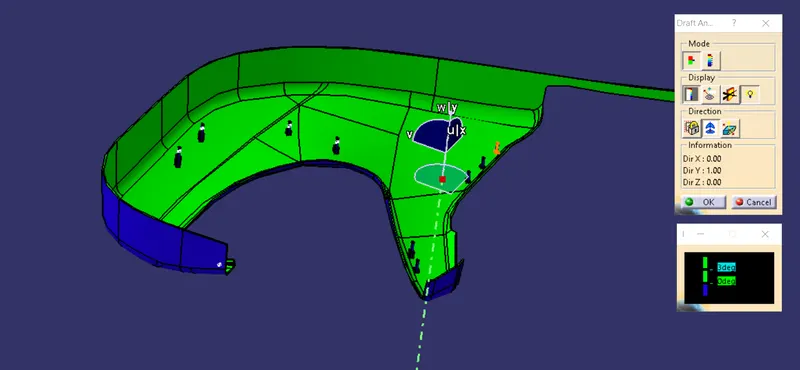
ARM REST
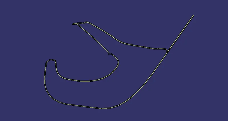
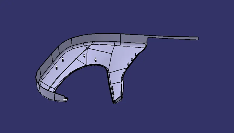
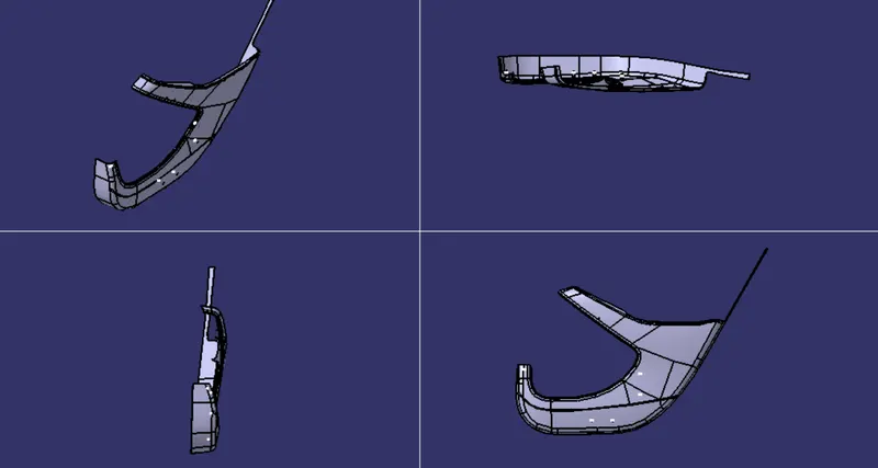
The C surface is made by sweeping the class A boundary as reference and then joining it with the class A and class B surface , a close surface is obtained . Thicken it to get a part body.
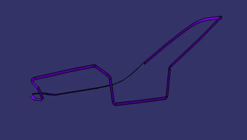
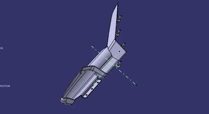
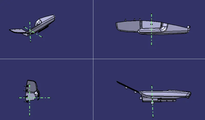
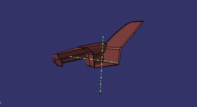
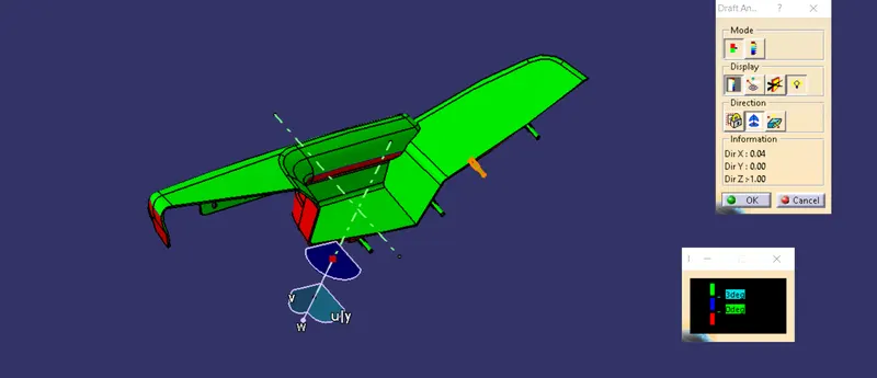
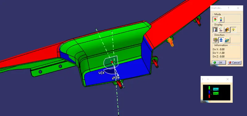
Here of the arm rest in order to perform the draft analysis properly , a slideing tooling axis is required along side the main tooling axis as it cannot be tooled with the regular tooling axis.
B SIDE ATTACHMENT FEATURES
B side features are created for the proper fixation of the parts on to the required surfaces.
FLANGES , HEAT STAKES AND OTHER FEATURES
DOG HOUSE AND PUSH PIN
FINAL ASSEMBLY