Fender Design Challenge
FENDER
Fender of a car is the part which protects the car from foreign unwanted particles such as dust, mud, water of all types of chips from the tyre from being entered into the engine bay or stopping this same chip from being thrown towards pedestrians. A good design fender will do all this along with being pleasing to the eyes. Ultimately the part should be appealing to the customer.
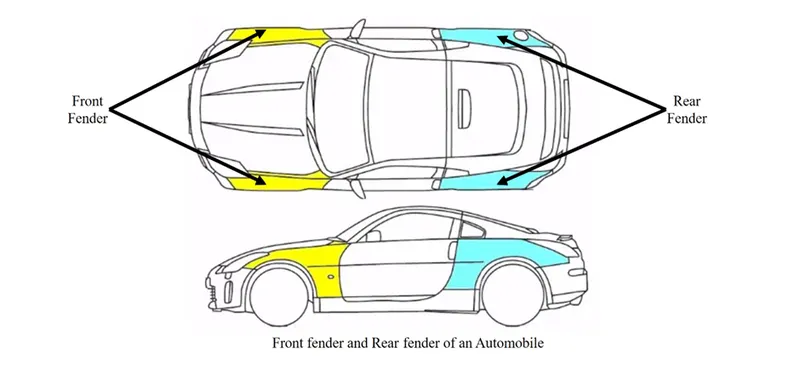
The above picture shows the front and the back fenders of a car. Here we can see front and back fender marked in the image. The front fenders are designed as an individual part and the back fenders are designed along with the body pillars. Front fenders are more important than the back fenders. Most of the cars have four fenders over four wheels. Some vehicles have a narrow body, in that case the fender will be an exposed curve over the tyre. For vehicles with wide body the fender will cover over the tyre. In this type fender will form a wheel well over the tyre.
The size of the tyre will be smaller than that wheel well, because if its not like that, then the tyre suspension travel won’t be happening blocking the full range of motion for suspension and allowing the tyre to move freely inside the wheel well up and down without touching the inside of the wheel well faces.
There are two types of fenders,
- Full bumper type
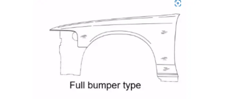
In this type more material is needed for the design the fender, hence more wastage of material. This design will also add on to the weight of the car as there is more sheet metal is used in this design.
- Half bumper types
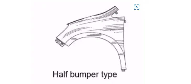
In this type less material is used to design the part hence less wastage of material that leads to less cost. This design will allow to use more plastic on the bumper so the weight of the car can be reduced to a certain extend. This type of fenders is now widely used in the industry.
MANUFACTURING PROCESS
Just like all the sheet metal parts, raw materials undergo various manufacturing processes to gain its purposeful shape and size. Basic manufacturing processes involved in manufacturing of BIW parts are:
- BLANKING
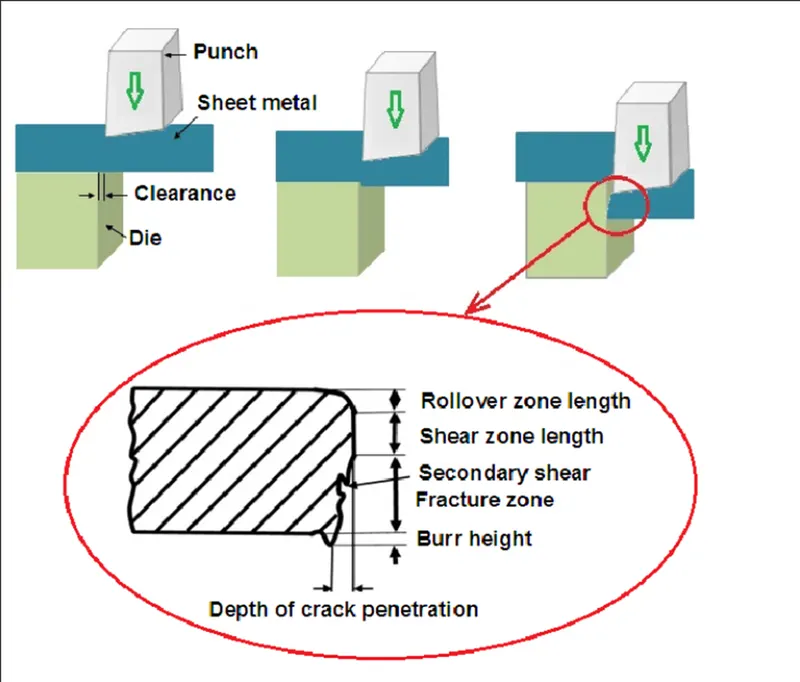
This process is for cutting the sheet metal into desired size for a particular component
- DRAWING/ FORMING
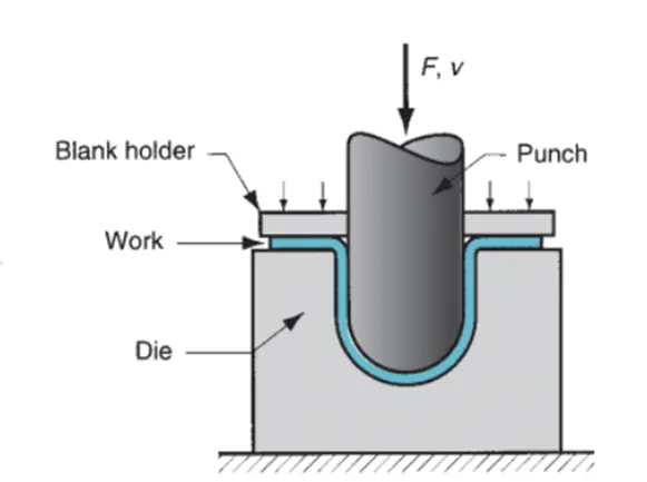
This process is responsible for shaping the sheet metal according to the component.
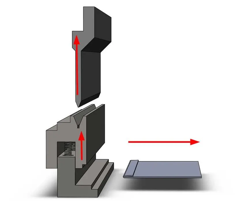
- PIERCING/NOTCHING/HEMNMING
These are kind of a post-production operation done after some main manufacturing process specifically for meeting some design requirements.
PIERCING is the operation which is done to give holes to the component
NOTCHING is done to provide notches to the part
HEMMING is a process of joining to flat sheet metal by folding its edges in a particular angle. This is done in places where welding and other joining process are not an option. For example, Class-A and the inner part of the automotive parts cannot be joined by welding due to aesthetic reasons. In that case hemming is used.
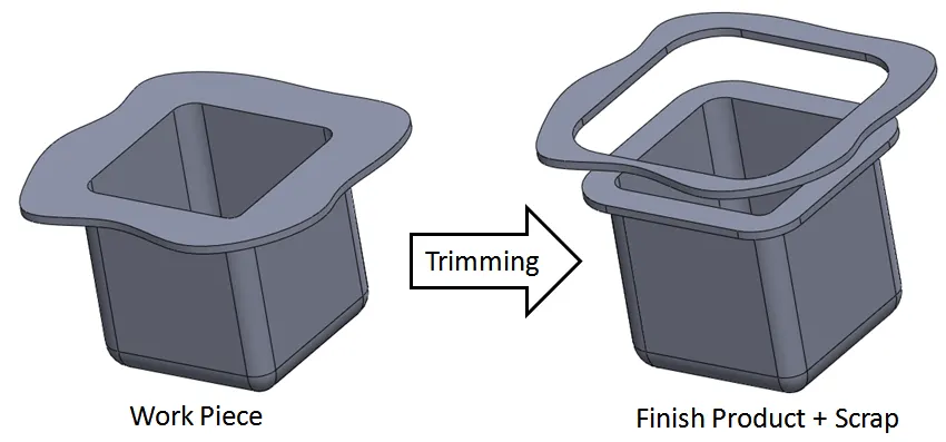
- TRIMMIG
Trimming is done to remove excess material from the final product.
In this challenge, I am going to be developing half bumper type front bumper. The main things I will be showing with this project is about the design consideration for designing the mountings on the class a surface. This mounting will get attached to several different parts of the car, giving the fender a good fit with the car’s rest of the body parts.
DESIGN INPUT
Master Section
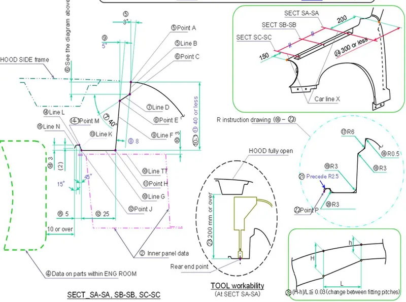
The above shown master section along for the drip area mounting and a CLASS A surface is given as input to begin with. The rest of the mounting’s design considerations are assumed based on this master section and also considering the industry standards.
From this master section we can see the information on how to design the drip area mountings for the fender. In the master section it is given that the drip mounting should be located at 150mm from the bumper and should maintain a gap of 200mm from the A pillar. Also, the details on the fillets are given in the master section for the drip area.
MOUNTINGS.
Then fender get attached to the car like all other body parts of the car. For mounting the fender to the body of the car, we obviously need different mountings for fender. These mountings are purpose fully designed for different areas of the car which the different sides of fender going to get mounted. Here we are designing the mountings for the following regions of the fender.
- DRIP AREA
- BUMPER AREA
- SIL AREA
- BAFFLE AREA
- A PILLAR AREA
DRIP AREA
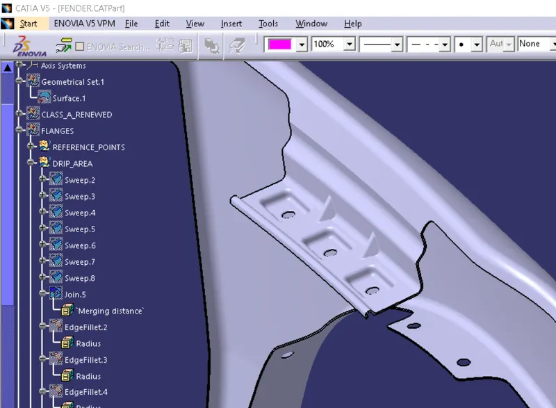
Drip area is located at the engine compartment of the car. This is the primary mounting of the fender and given more priority as well because of the face that this mounting has more length as an individual mounting while comparing with the other mounting on the fender. According to the master section given, the drip area mounting is created with a minimum distance of 150mm from the front region of the engine bay and a distance of 300mm is kept from the back region of the engine bay. The mounting and the fender connection should be at an approx. distance of 10mm. As shown in the master section the length from point A to point H (length of the mounting) should be less than 40mm to avoid the spring back in the manufacturing process. It’s better to give at least 3 weld bolt holes of M6 standard. As the length of this mounting is more, its better to give more reinforcements like stiffeners or any other design speciality which improve the strength and rigidity to this mounting. Fillets are given at particular amount at particular places according to the master section. Also, minimum fillets are given at undefined areas for better manufacturability.
BUMPER AREA
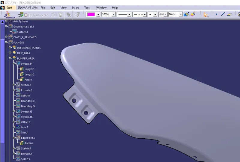
Bumper areas as the name is for mounting the fender onto the bumper portion of the car. This is a small mounting compared to the drip area mounting. Here we can give one or more weld bolt hole for mounting. Fillets and other design considerations are done similarly as the drip area mount.
SIL AREA
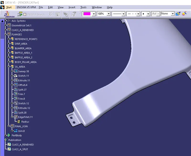
This area comes between the bottom portion of the fender and the bottom portion of the car body. This mount is crucial for a firm mounting of the fender to the body. This mount is the smallest mount in the fender part. Fillets and other design considerations are done similarly as the drip area mount.
BAFFLE AREA
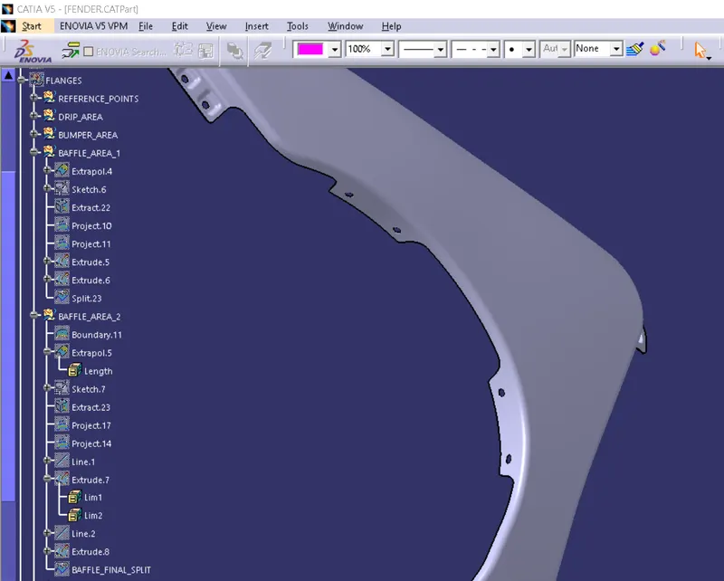
This mounting is very crucial for keeping the NVH levels down in the car. This mount comes near the wheel arch portion of the car. This mount can be designed in two or more sections to give the assembly a firm fit. Mostly the design of this mounting can be done as a simple extension from the fender part.
A-PILLAR AREA
This mount connects the fender with the body or the a-pillar together. This can be done with a single or a double bolt. But for a firm fit, more than single bolt is recommended.
THICKEN
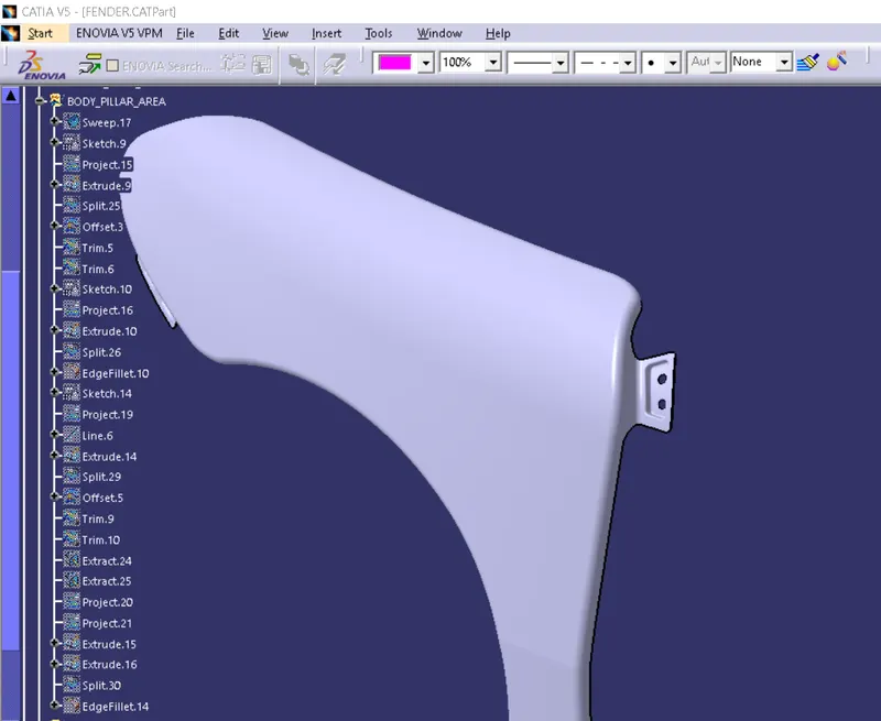
After creating all the mounting points, they are joined with the part and given a thickness of 0.75mm. Also, all the necessary fillets are given with appropriate values on the sharp edges.
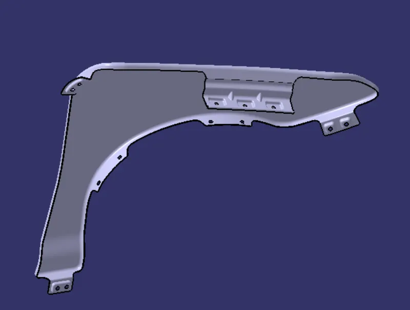
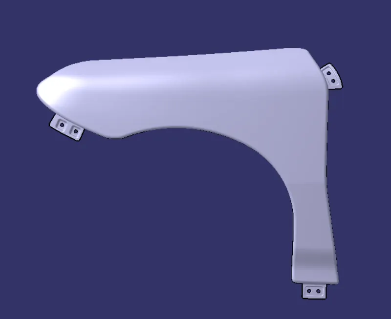
FINAL COMPLETED VIEWS OF THE PART
CONCLUSION
For this project I was able to design the mounting points for the given fender design according to the master section and design the mounting points in such a way that it was highly manufacturable by following the industry standard parameters