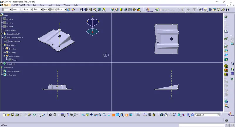
Base Bracket Design
AIM
To create the Base Bracket Plastic component through the given Class- A surface and also perform draft analysis on it at the end.
PROCEDURE
Step 1
-
Import the given Class-A surface model in Catia workbench
-
Visually check and fix a proper tooling direction
-
Check whether the model has a continuous boundary by using boundary command
Step 2
-
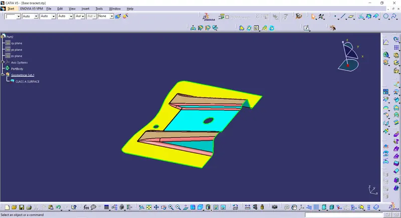
Identify the surface which could create problems for the to tooling axis
-
Here Z axis is the possible direction for tooling
Step 3
-
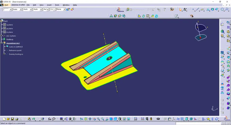
Make a dummy tooling axis for refrerence
-
Set a different colour for the planes which will create problems while tooling for a reference. Make sure the choosen colour is not a pre defined colour in catia.
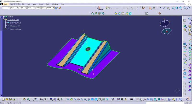
Step 3
-
Intersect the class-A surface with the y direction and obtaint the curve.
-
Create the bisecting lines for making the tooling axis
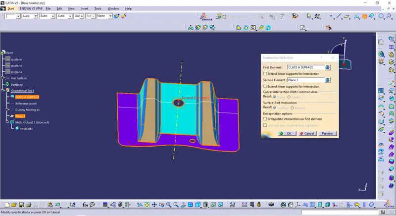
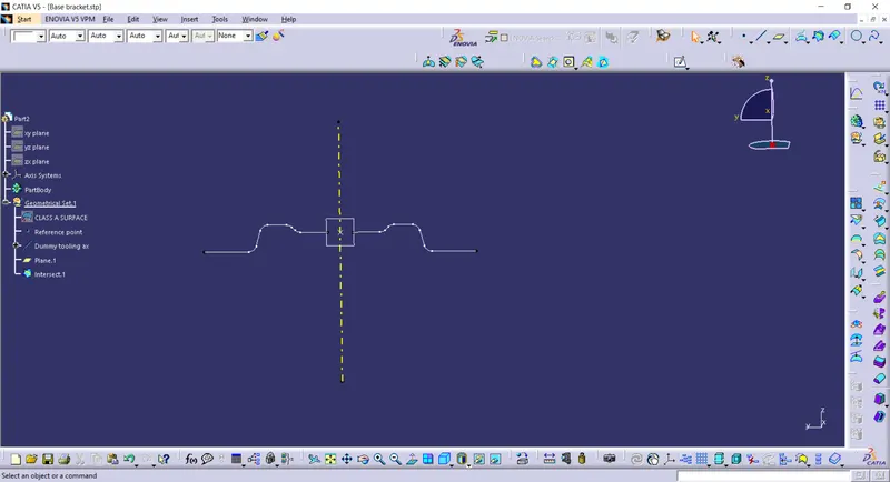
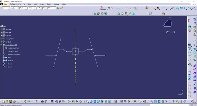
Step 4
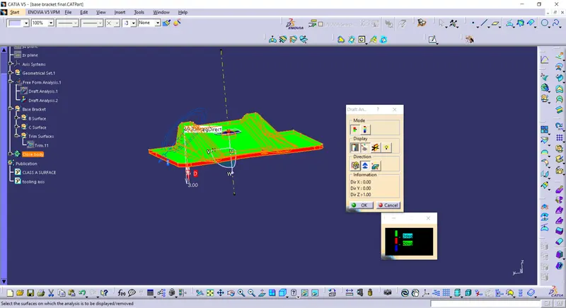
Draft Analysis
-
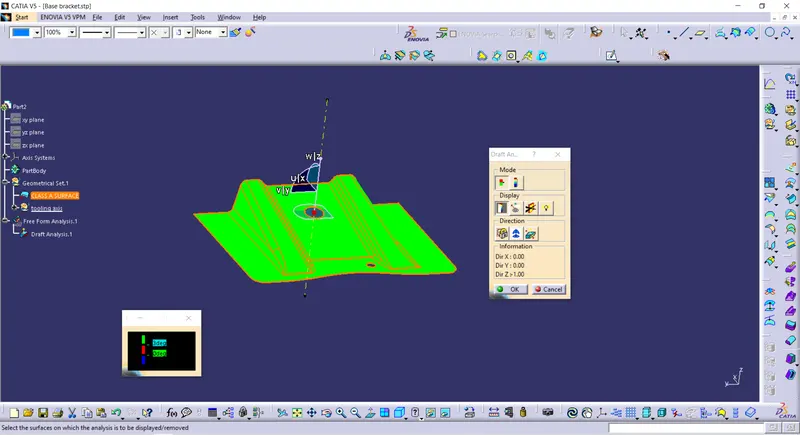
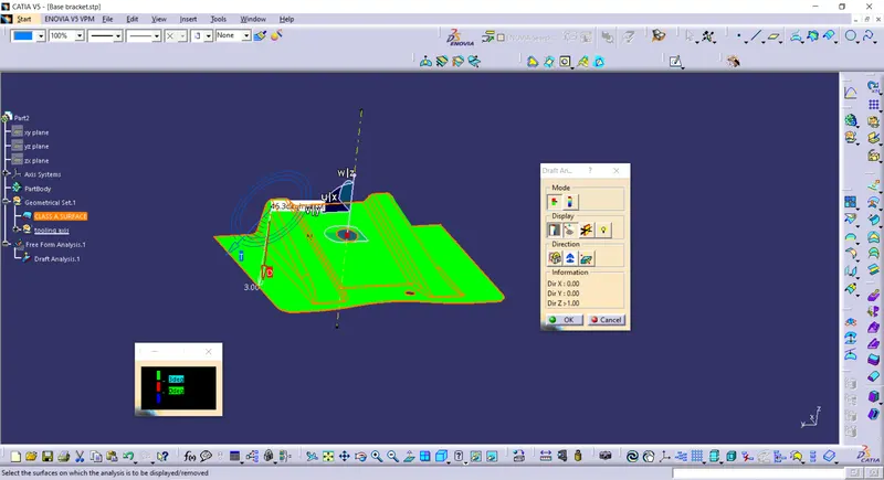
Open the Feature Draft Analysis command
-
Click on the compass button and align the red dot on the axis with the tooling axis of the component.
-
Next select the component, and use the manual draft angle analysis to make sure everything is ok.
Step 5
Creating B surface
-
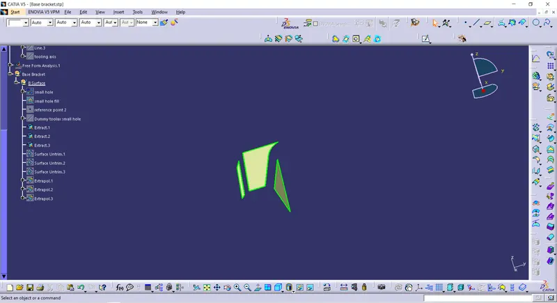
Consolidate different types of surfaces like base , slope and ribs using different colours.
-
Extract the surface with no propagation.
-
Untrim the obtained surfaces, then extrapolate the surface.
-
Then trim the extrapolated surface.
-
Offset the output for 2.5 mm.
-
Change the colour for reference
Run the same step for all the surfaces (Base , slopes and ribs).
-
Later trim the different surface together to obtain the B surface
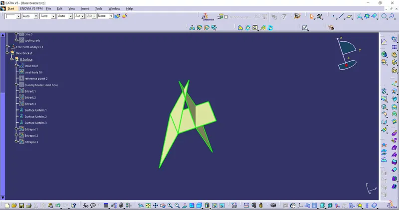
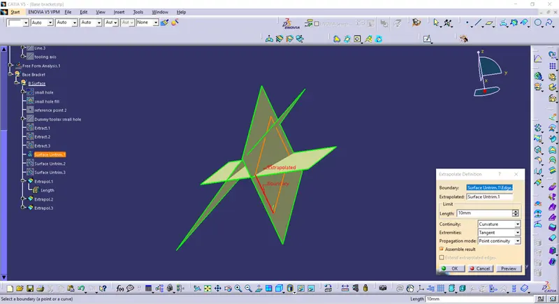
- Same is done for the rib on the other side
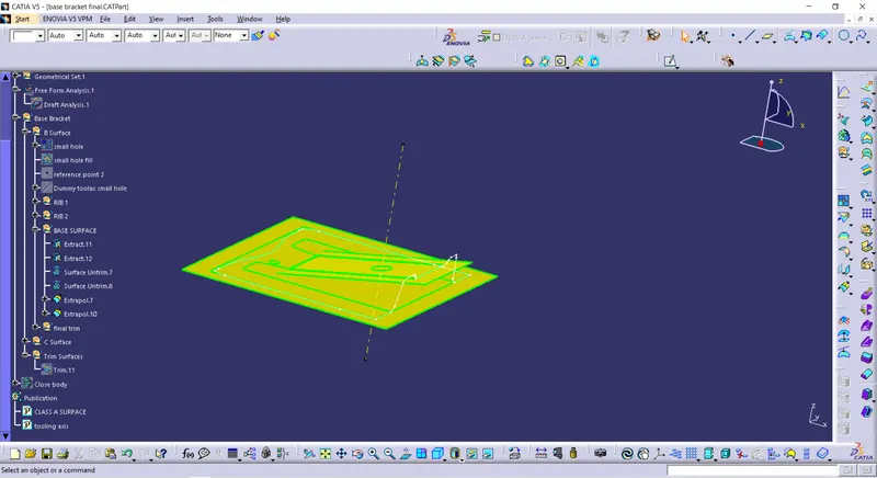
- The base and the ribs are trimmed together to obtain the following output
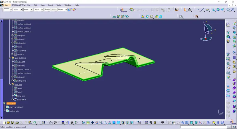
Step 6
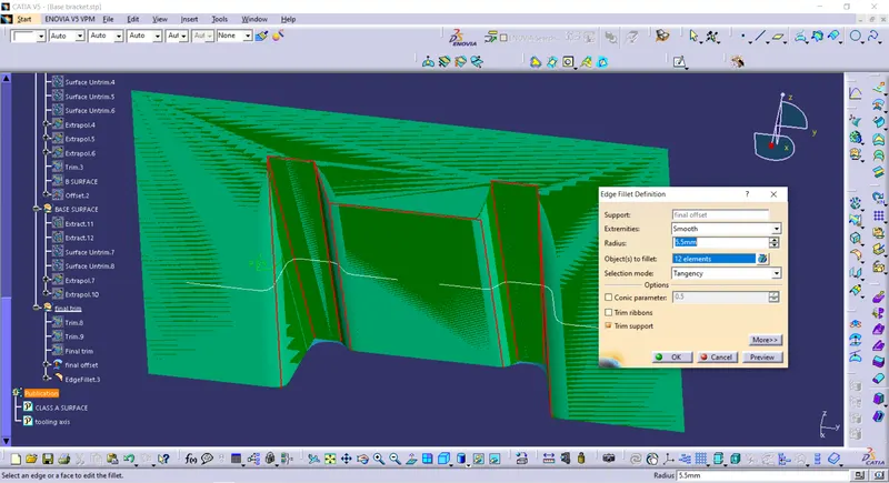
Fillet the B surface with proper values.
For inside fillet radius : r = desired value of fillet + thickness of component
For outside fillet radius : r = desired value of fillet - thickness of component
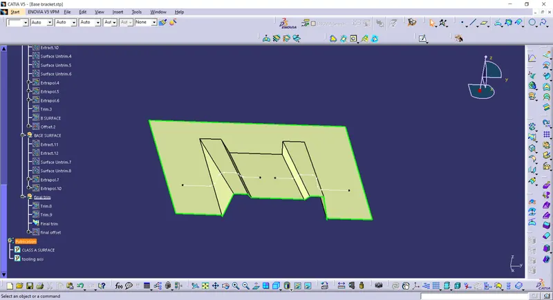
Step 7
Creating C surface
-
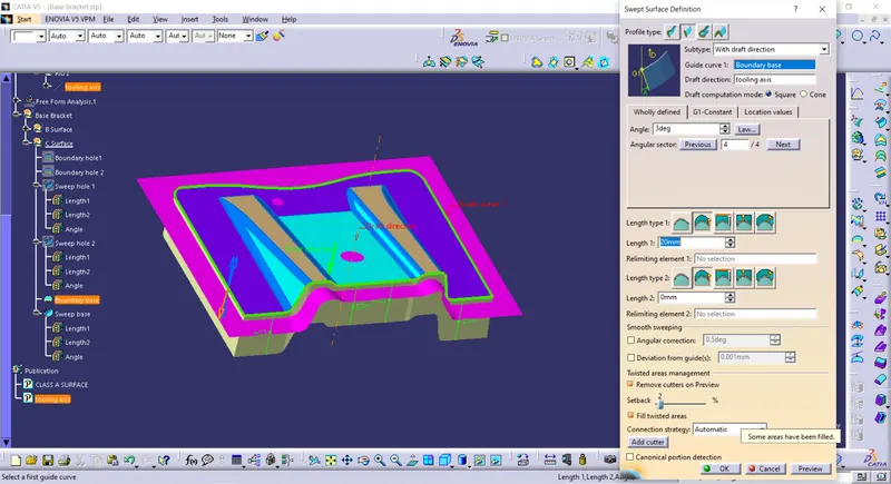
Check the boundary and makesure its extrapolated atleast an extra 5mm
-
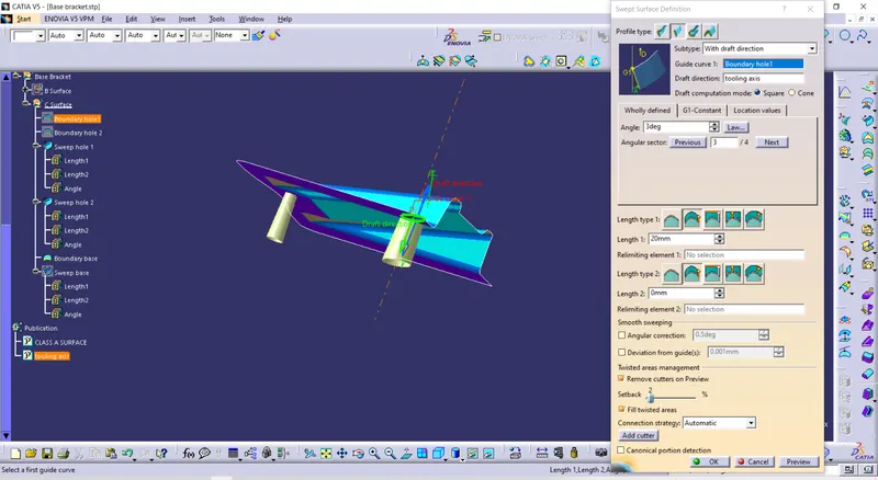
Extract the boundary from class A and create a sweep using it. Select the tooling axis as the draft direction for sweep and slect the downward direction , do the same for the holes as well
Step 8
-
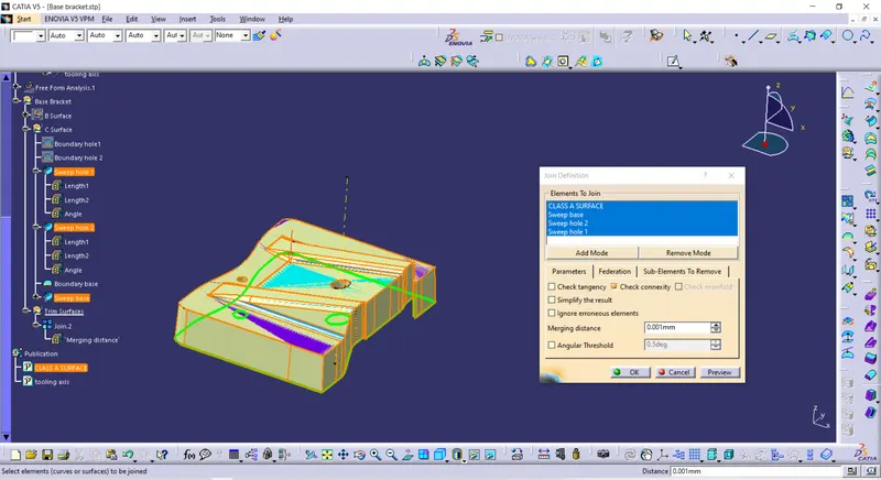
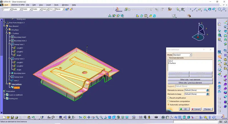
Join all the C surface with the A surface and trim it with the B surface
Step 9
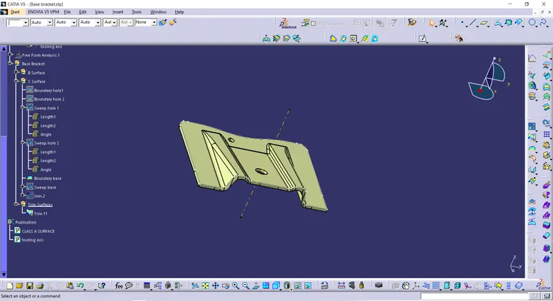
Now trim the b surface with the output got from joining A and C surfaces.
Step 10
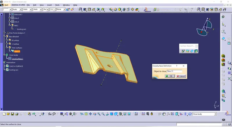
- Finally make a close body
Result
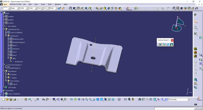
Base Bracket Plastic component through the given Class-A surface is created. The tooling axis for the given Class-A Surface is created meeting the requirements of the draft angle and performed the Draft analysis on the model.