Fender Design - Wheel Arch Challenge
WHEEL ARCH AREA CALCULATION
FENDER
Fender of a car is the part which protects the car from foreign unwanted particles such as dust, mud, water of all types of chips from the tyre from being entered into the engine bay or stopping this same chip from being thrown towards pedestrians.
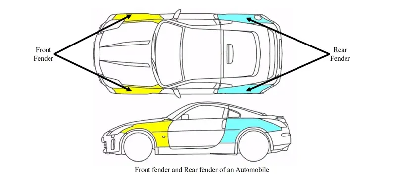
The above picture shows the front and the back fenders of a car. Here we can see front and back fender marked in the image. The front fenders are designed as an individual part and the back fenders are designed along with the body pillars. Front fenders are more important than the back fenders.
There are two types of fenders
- Full bumper type
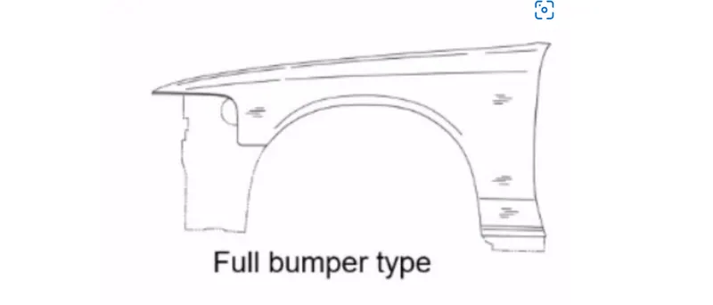
In this type more material is needed for the design the fender, hence more wastage of material. This design will also add on to the weight of the car as there is more sheet metal is used in this design.
2. Half bumper type
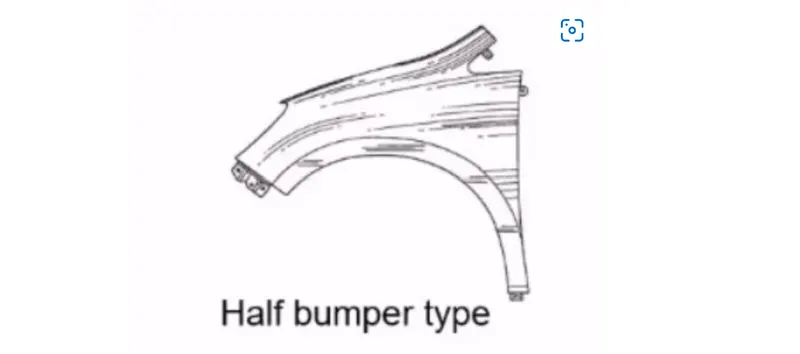
In this type less material is used to design the part hence less wastage of material that leads to less cost. This design will allow to use more plastic on the bumper so the weight of the car can be reduced to a certain extend. This type of fenders is now widely used in the industry.
WHEEL ARCH
Wheel arch of the car is portion which houses the wheels of the car. It’s the semi-circular region of the fender. Wheel arch of a car will be having some standard specification. The wheel cannot be outside the fender as it will lead to more chipping from the tyre. This is not good for the car and the pedestrians. So, by keeping this the pedestrian’s safety in mind, the tyre position should be inside the fender. This regulation changes according to the region. So, it is important to keep those regulations in mind while designing the fender and its wheel arch.
WHEEL ARCH REGUALTIONS
According to the regions there are 3 main standards to the wheel arch design. This regulation is fixed by the road safety authorities of that particular regions. Those standards are:
- Japanese standard
- European standard
- United States standards
JAPANSE STANDARD
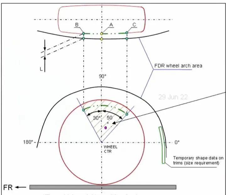
Here as shown in the picture, from the wheel centre vertical axis point. Two lines should be created and should be having 30 degrees to the left and 50 degrees to the right from the centre axis. Then on projecting the line on to the wheel arch, the distance (L as shown in the figure) between the intersecting points on the wheel and the wheel arch is allowed to have a minimum of 5mm distance at all three points (A, B and C). This is the Japanese standard.
EUROPEAN STANDARD
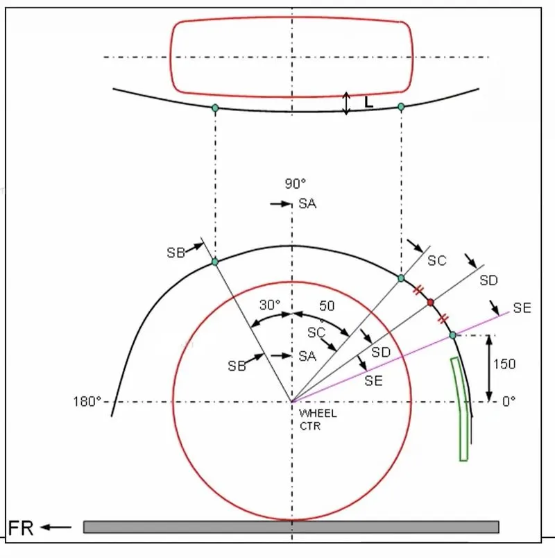
Here as shown in the picture, from the wheel centre vertical axis point. Three lines SB, SA and SC should be created and should be having 30 degrees to the left for SB, SA passing 90 degrees through the centre axis and 50 degrees to the right from the centre axis for SC. Then after creating those three lines, a 150 mm point should be marked on the wheel arch reference and a line should be created from the centre point passing through the point on the wheel arch reference. That line is called SE. Then another line should be created intersecting SC line and SE line. Then on projecting the line on to the wheel arch, the distance (L as shown in the figure) between the intersecting points on the wheel and the wheel arch is allowed to have a minimum of 10mm distance at all the points. This is the European standard.
UNITED STATES STANDARD
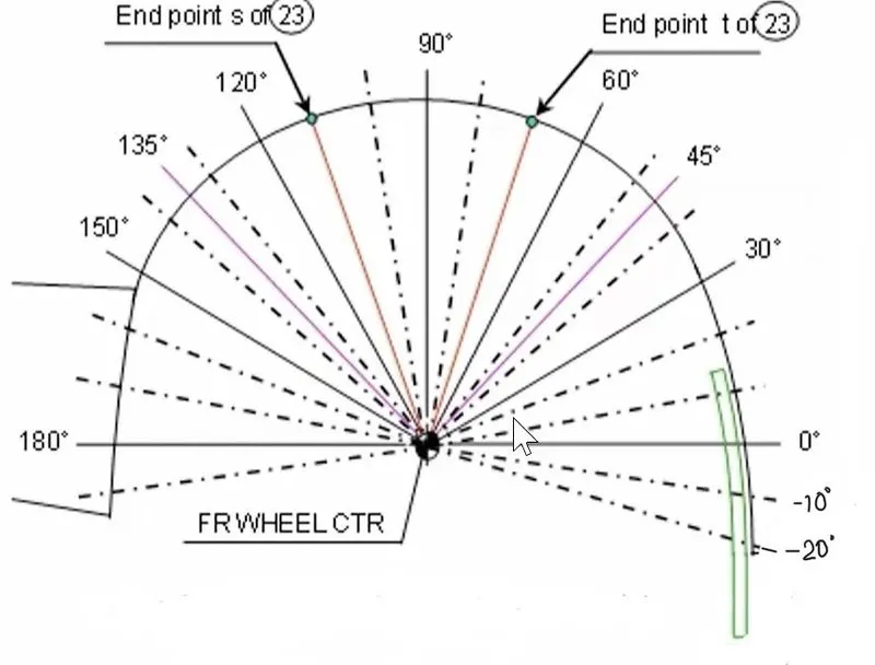
For united state regulation, the concept is the same but the point should be taken on every 10 degrees from -20 degree to 0 and a minimum gap between the wheel and wheel arch should be 5 mm at all of those points. This is the United States requirement.
If the same car design is done for different markets for example Japan, Europe and US, the we are allowed to consider the maximum clearance value which will cover most of the regional requirements are we cannot make different designs for a same car as it will be inefficient.
WHEEL ARCH CALCULATION BASED ON EUROPEAN STANDARD FROM THE GIVEN 3D DATA.
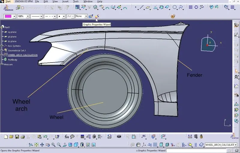
The 3D data has been imported into the CATIA and a reference sketch is made according to the regulations.
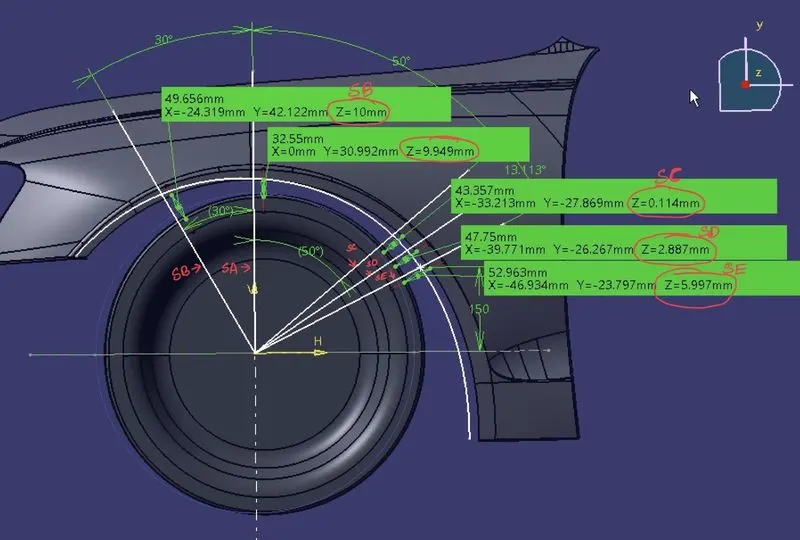
The values have been measured between wheel and wheel arch. The red circled Z axis values represent the values.
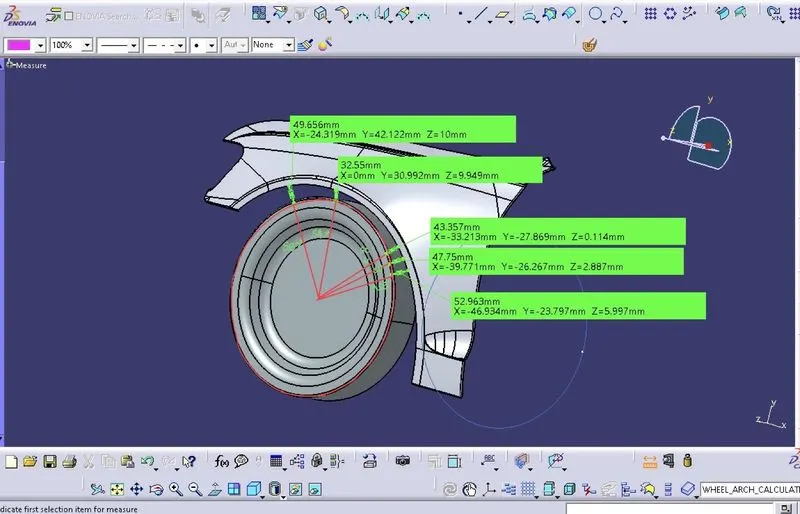
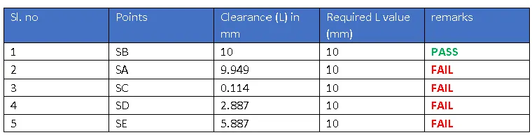
The data has been tabulated below.
CONCLUSION
- As we can see from the data, the fender design will not qualify the European standards.
- The point SB meets the requirement and that point does not need any modification
- Here the last 3 points that is, SC, SD and SE are protruding outside. So, those poinst needs modification.
- The data will be forwarded to the styling team for further analysis and modification