Week 6 - CHT Analysis on a Graphics card
Aim:
Analysis of steady-state conjugate heat transfer using a graphics card model
Objectives:
- Run the simulation by varying the velocity from 1m/sec to 5m/sec for at least 3 velocities and discuss the results.
- Find out the maximum temperature and heat transfer coefficient attained by the processor.
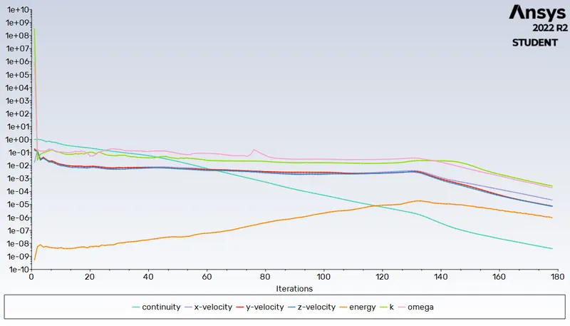
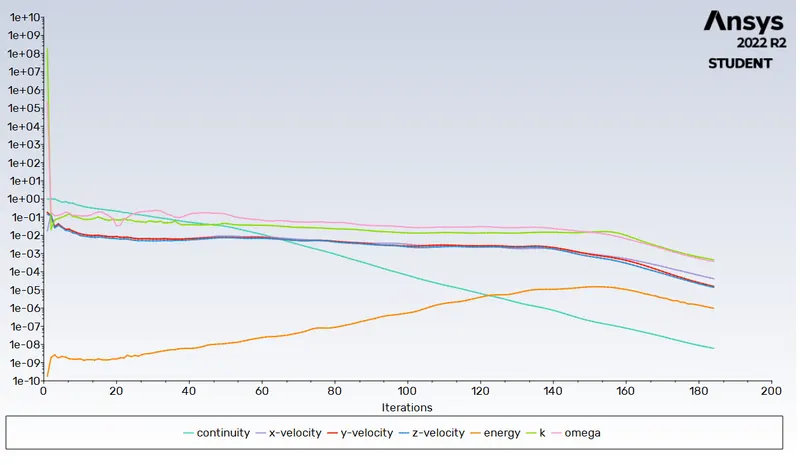
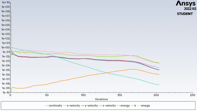
- Prove that the simulation has achieved convergence with appropriate images and plots.
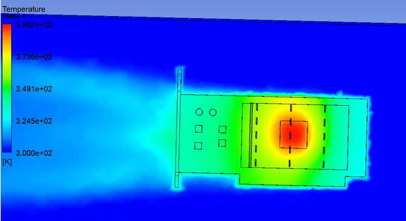
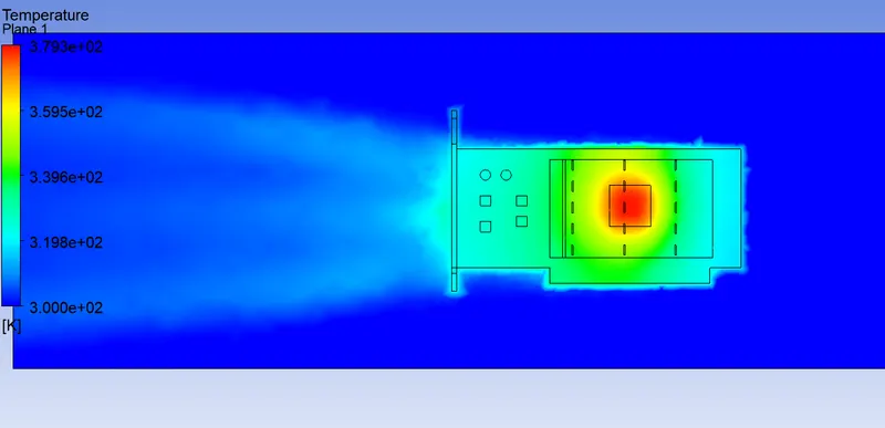
- Identify potential hotspots on the model.
Procedure:
Conjugate Heat Transfer (CHT):
Conjugate heat transfer analysis addresses the heat transfer between a body and a fluid running over or inside it as a result of interaction between two objects. It is based on a mathematically structured problem. The details of the temperature distribution and heat flux along the interface at the matching interface eliminate the need to calculate the heat transfer coefficient. Additionally, it is possible to determine the heat transfer coefficient later.
Numerical approaches are one of the simplest ways to realise conjugation. Iterative methods are used to set and solve the boundary conditions for the interface between a fluid and a solid. Other than by using the hit-and-miss approach, there is no way to make accurate assumptions about the values of the initial boundary condition for convergence.
Application:
The conjugate heat transfer methods have improved as a modelling and research tool for engineering systems and natural phenomena in a variety of fields, such as aerospace and nuclear reactors, thermal goods processing, food processing, complex medical procedures, ocean thermal interaction, and metrology.
Through the design of heat sinks and heat exchangers for the waste treatment plant, CHT has greatly improved the cooling performance of electronic equipment in recent years. The exhaust port system is one such CHT use.
Solving & Modelling approach:
- Graphic card file is loaded into the spaceclaim
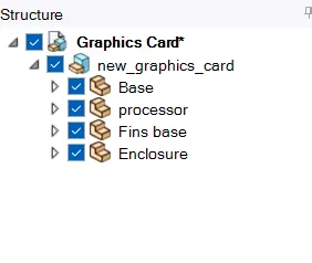
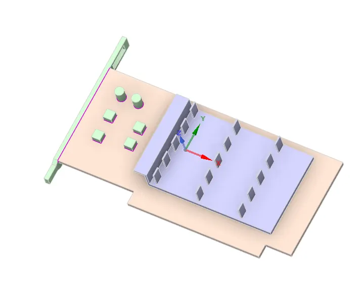
- The graphics card consists of a processor, PCB base, aluminum fin base, memory cards, and capacitors.
- The solid and liquid volume under consideration are both necessary for CHT analysis, and Spaceclaim offers a volume extract option for choosing edges for fluid volume. In this case, the solid and liquid volume under consideration are air and the components of the graphics card.
- The underlying theory of how air carries away the heat produced by the CPU. The fin is utilised to increase the heat transfer surface area.
- The share topology is configured to make the mesh conformal and to lower interpolation error.
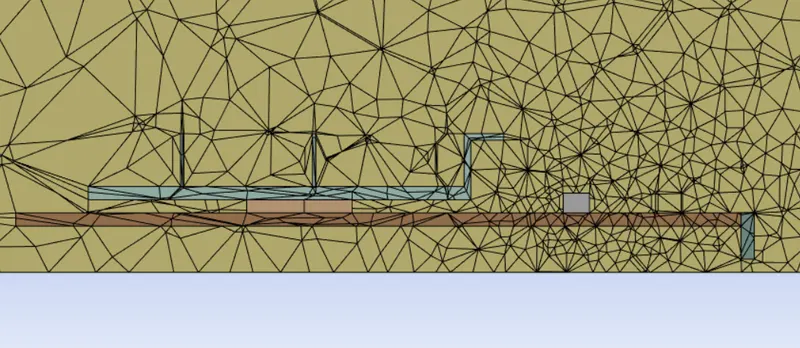
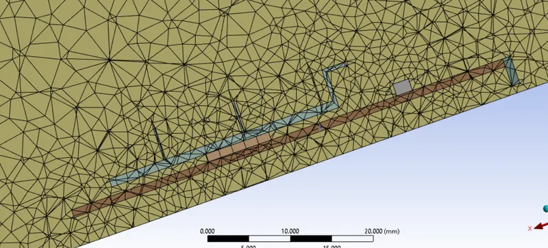
- The meshing window is then loaded, where the named selection is made and the baseline mesh and refined mesh are set.
- The construction of the material is chosen. the fluid material and the solid material are separated.
- To comprehend the behaviour of temperature, velocity, and surface heat transfer coefficient at the interface, the relevant contour images and graphs are reviewed.
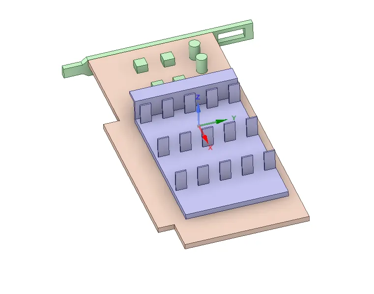
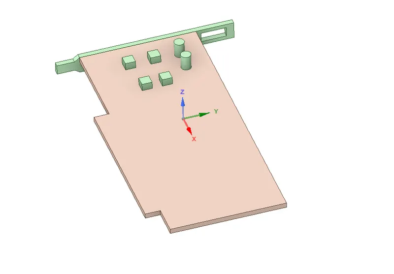
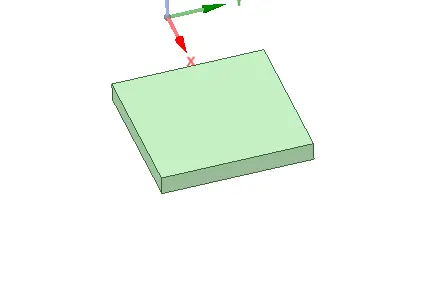
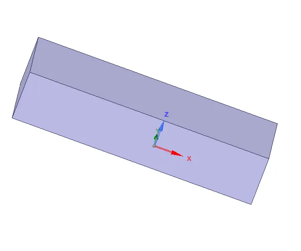
BASE PROCESSOR
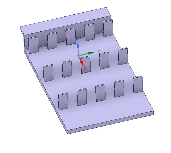
FINS ENCLOSURE
MESHING:
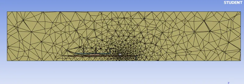
BASELINE MESHING
Mesh Size : Default size
- A basic mesh is generated using the standard values recommended by Ansys. This mesh is used to obtain an initial solution which will help us to determine the location where mesh refinement is required
REFINED MESH
Base – 0.5 mm
Processor – 0.25 mm
Fins – 0.2 mm
Outer enclosure – 3.9mm
SETUP & SOLUTION:
1.Solver: Steady
2.Type: Pressure Based
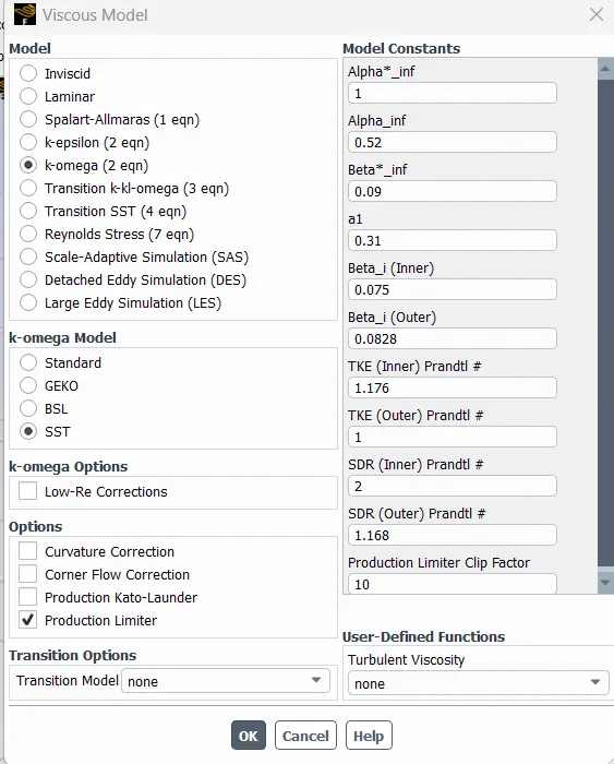
3.Turbulence Model: k-Omega(SST)
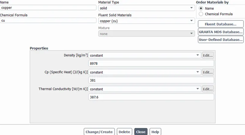
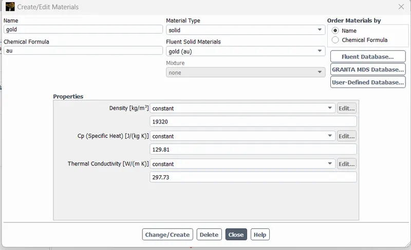
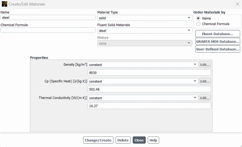
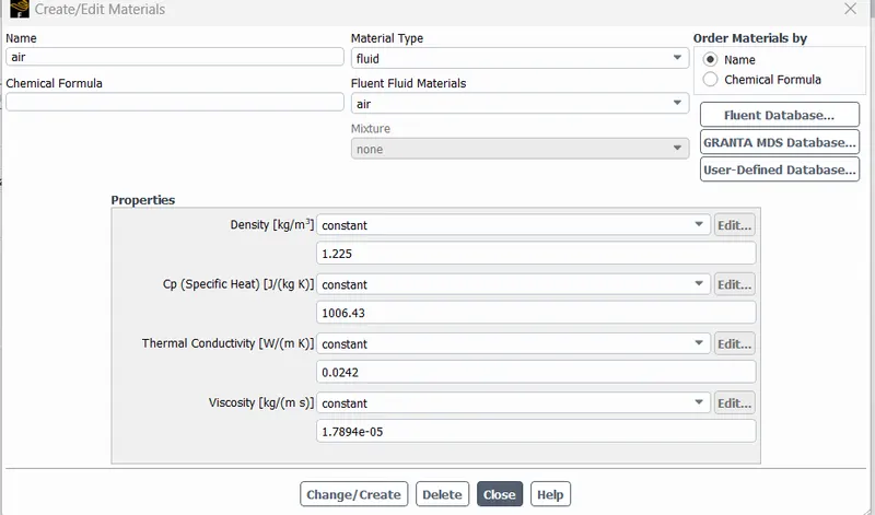
4.Materials: Different materials are used for each part
FOR COPPER,
FOR GOLD,
FOR STEEL,
FOR AIR,
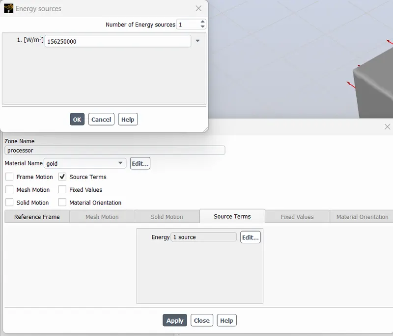
The processor is assumed as the only source of heat. The heat generated by the processor is calculated as:-
Graphics Card Power = 10W
Volume of the card = 8 x 8 x 1
=64mm^3
=64e−9m^3
Heat Generated = P/V
=10/64e−9
=1.5625e8 (W/m3) `
Solution:
- Method: Standard
- Number of Iterations: 150
CASE 1 :
Inlet Velocity= 1 m/s
RESIDUAL PLOT:
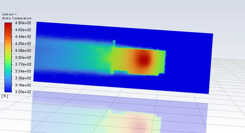
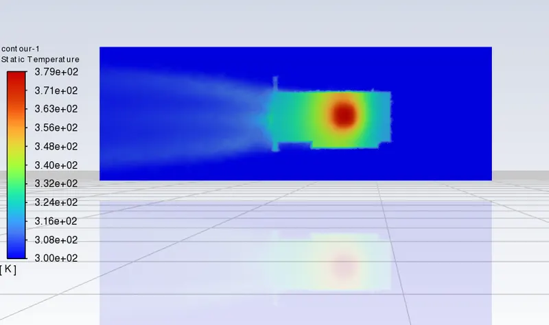
TEMPERATURE CONTOUR:
TEMPERATURE PLOT:(HOTSPOT AROUND THE PROCESSOR)
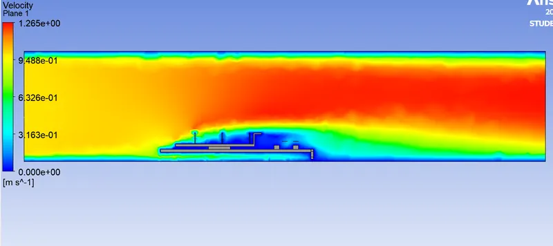
VELOCITY PLOT:
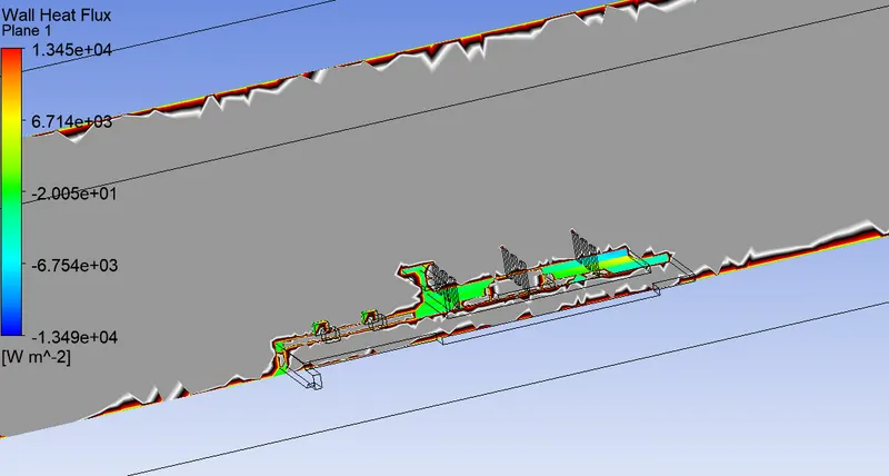
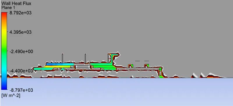
HEAT FLUX:
CASE 2 :
Inlet Velocity= 3 m/s
RESIDUAL PLOT:
TEMPERATURE CONTOUR:
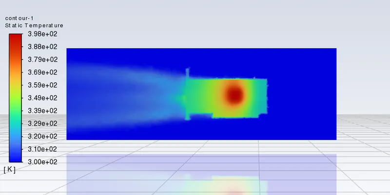
TEMPERATURE PLOT: (HOTSPOT AROUND THE PROCESSOR)
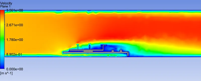
VELOCITY PLOT:
HEAT FLUX:
CASE 3 :
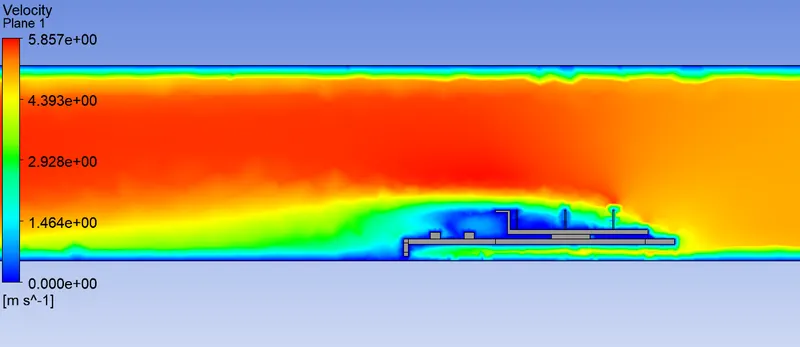
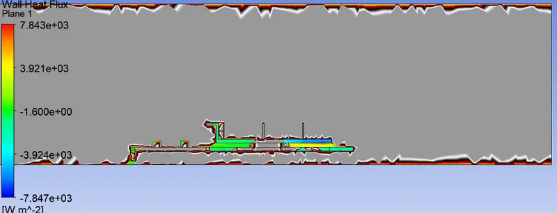
Inlet Velocity= 5 m/s
RESIDUAL PLOT:
TEMPERATURE CONTOUR:
TEMPERATURE PLOT: (HOTSPOT AROUND THE PROCESSOR)
VELOCITY PLOT:
HEAT FLUX:
| Velocity (m/s) | 1 | 3 | 5 |
|---|---|---|---|
| Temperature at proccessor (K) | 480 | 398.2 | 379.3 |
RESULTS:
- As the number of elements increases the accurate results of temperature distribution is obtained
- From the above table, it is fairly notable that, the net temperature of components of graphics cards decreases with an increase in inlet velocity.
- Hence it can be inferred that a higher inlet velocity results in better cooling and lower the average temperature thus keeping the components safe from damage.
- Furthermore, it can be observed that the temperature of components increases as the inlet velocity decreases from 5 m/s to 1m/s, also proving that higher velocity results in better cooling.