Week 12 - Validation studies of Symmetry BC vs Wedge BC in OpenFOAM vs Analytical H.P equation
AIM:
To validate studies of Symmetry BC vs Wedge BC in OpenFOAM vs Analytical H.P equation for flow along a pipe using OpenFOAM.
OBJECTIVE:
- Validate Hydro-dynamic length with the numerical result
- Validate the fully developed flow velocity profile with its analytical profile
- Validate maximum velocity and pressured drop for fully developed flow
- Post-process Shear stress and validate wall shear stress for fully developed flow
- Highligh the differences in both boundary conditions in terms of their usage and application
Angles to test:45o">
- 10 deg
- 25 deg
- 45 deg
PROCEDURE:
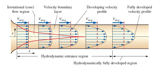
- The above image shows two regions hydrodynamic entrance region and fully developed region, the entrance length is the distance a flow travels after antering the pipe.
- This length refers to length of thr entry region, the area following the pipe entrance whare the effect originating from the unterior wall of the pipe propogate into the flow as an expending boundary layer.
- When the boundary layer expands to fill the entire pipe, the developing flow becomes a fully developed flow, where flow characteristics no longer change with increased distance along the pipe.
- The hydrodynamic entrance region refers to thr area of a pipe where fluid entering a pipe develops a velocity profile due to viscous forces propagating from the interior wall of pipe.
- The region of flow in which the effects of viscous effects and velosity are suddenly changes is called as boundary layer.
- The boundary surface divides the flow in a pipe into two regions, the irrotational flow region and the boundary layer region
- The viscous affects the velocity changes are significant are in the boundary layer region, and friction effects are negligible and the velocity essentially remains in the radial directtion is the irrotational region
- The thickness of the boundary increases gradually with the flow, when it reaches mid-section the velocity profile becomes filly developed.
- This length where the flow converts to fully developed region from till the entry point, is called as hydridynamic entrance region.
- The flow in this region is called hydrodynamically developed flow since this is the region where the velocity profile develops and keeps changing.
- The flow in the region is fully developed flow and remains cinstant across the pipe, creating a parabolic velocity profile as shown in figure above
- The shear stress is directly proportional to the velocity gradient, thus the shear stress at wall is maximum and shear stress at center is minimum.
HAGEN-POISEUILLE EQUATION:-
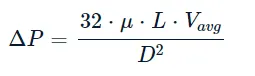
- In non fluid dynamics the hagen-poiseuille equation is a physical law that gives the pressure drop in an incompressible and newtonian fluid in laminar flow flowing throught a long cylinder pipe of constant cross section.
- The equations describes pressure drop as follows,
Wedge Boundary conditions
The wedge boundary condition (BC) is used in computational fluid dynamics to define an axisymmetric situation, for eg. cylinder. The model and flow must be axisymmetric along a central line such that all physical variables of the flow have the same value and distribution at a given radius for all angles.
This boundary condition is specified by two planes that must be selected on separate sides of the domain (referred to as front and back) on surfaces running along the axis. It works for 2D simulations only.
Symmetry Boundary conditions
The symmetry boundary condition defines a mirror face/surface. It should only be used if the physical object or geometry and the expected flow field pattern of the developed solution are mirrored along that surface. By using this boundary condition, the domain can essentially be halved, reducing the time to achieve a solution.
In detail, the symmetry condition applies the following constraints on the flow variables:
- The fluxes across the symmetry are zero.
- The normal components of all variables are set to zero.
It can be applied to both planar or non-planar faces/surfaces on the domain boundaries.
MATLAB CODE FOR WEDGE BOUNDARY CONDITION:
clear all
close all
clc

%Inputs:
l= 1.5;         %Length of the pipe.
theta = 45.0;    %Wedge angle.
d = 0.01;       %Diameter of the pipe.
c = 1.0;        %Conversion Factor.
r = d/2;        %Radius of the Cylinder.
nx = 500;       %number of Mesh points in x-direction on the block.
ny= 25;         %Number of Mesh points in the y-direction on the block.
nz= 1;          %number of Mesh Points in the z-direction on the block.
gx = 1;         %Grading along the x-direction.
gy = 1;         %Grading along the y-direction.
gz = 1;         %Grading along the z-direction.


f1 = fopen('BlockMeshDict.txt','w');
fprintf(f1,'/*--------------------------------*- C++ -*----------------------------------*n');
fprintf(f1,'  =========                 | n');
fprintf(f1,'        /  F ield         | OpenFOAM: The Open Source CFD Toolbox n');
fprintf(f1,'       /   O peration     | Website:  https://openfoam.org n');
fprintf(f1,'      /    A nd           | Version:  10 n');
fprintf(f1,'     /     M anipulation  | n');
fprintf(f1,'/*------------------------------------------------------------------*/ n');
fprintf(f1, 'FoamFile n');
fprintf(f1,'{ n');
fprintf(f1,'    format      ascii; n' );
fprintf(f1,'    class       dictionary; n');
fprintf(f1,'    object      blockMeshDict; n');
fprintf(f1,'} n');
fprintf(f1,'// * * * * * * * * * * * * * * * * * * * * * * * * * * * * * * * * * * * * * // n');

fprintf(f1,'convertToMeters %0.1f; n',c);
fprintf(f1,'n');
fprintf(f1,'vertices n');
fprintf(f1,'( n');
fprintf(f1,'(0 0 0) n');
fprintf(f1,'(%0.6f %0.6f %0.3f)n',r*sind(theta/2),r*cosd(theta/2),0);
fprintf(f1, '(%0.6f %0.6f %0.3f)n',-r*sind(theta/2),r*cosd(theta/2),0);
fprintf(f1,'(0 0 %0.3f) n',-l);
fprintf(f1,'(%0.6f %0.6f %0.3f)n',r*sind(theta/2),r*cosd(theta/2),-l);
fprintf(f1, '(%0.6f %0.6f %0.3f)n',-r*sind(theta/2),r*cosd(theta/2),-l);
fprintf(f1,'); n');
fprintf(f1,'n');

fprintf(f1,'blocks n');
fprintf(f1,'( n');
fprintf(f1,'hex (0 3 5 2 0 3 4 1) (%0.0f %0.0f %0.0f) simpleGrading (%0.0f %0.0f %0.0f) n',nx,ny,nz,gx,gy,gz);
fprintf(f1,'); n');
fprintf(f1,'n');

fprintf(f1,'edges n');
fprintf(f1,'( n');
fprintf(f1,'); n');
fprintf(f1,'n');

fprintf(f1,'boundary n');
fprintf(f1,'( n');
fprintf(f1,'in n');
fprintf(f1,'{ n');
fprintf(f1,'type patch; n');
fprintf(f1,'faces n');
fprintf(f1,'( n');
fprintf(f1,'(0 1 2 0) n');
fprintf(f1,'); n');
fprintf(f1,'} n');

fprintf(f1,'out n');
fprintf(f1,'{ n');
fprintf(f1,'type patch; n');
fprintf(f1,'faces n');
fprintf(f1,'( n');
fprintf(f1,'(3 5 4 3) n');
fprintf(f1,'); n');
fprintf(f1,'} n');

fprintf(f1,'ft n');
fprintf(f1,'{ n');
fprintf(f1,'type wedge; n');
fprintf(f1,'faces n');
fprintf(f1,'( n');
fprintf(f1,'(0 3 4 1) n');
fprintf(f1,'); n');
fprintf(f1,'} n');

fprintf(f1,'bk n');
fprintf(f1,'{ n');
fprintf(f1,'type wedge; n');
fprintf(f1,'faces n');
fprintf(f1,'( n');
fprintf(f1,'(3 0 2 5) n');
fprintf(f1,'); n');
fprintf(f1,'} n');

fprintf(f1,'top n');
fprintf(f1,'{ n');
fprintf(f1,'type wall; n');
fprintf(f1,'faces n');
fprintf(f1,'( n');
fprintf(f1,'(5 2 1 4) n');
fprintf(f1,'); n');
fprintf(f1,'} n');

fprintf(f1,'axis n');
fprintf(f1,'{ n');
fprintf(f1,'type empty; n');
fprintf(f1,'faces n');
fprintf(f1,'( n');
fprintf(f1,'(0 3 3 0) n');
fprintf(f1,'); n');
fprintf(f1, '} n');

fprintf(f1,'); n');
fprintf(f1,'n');

fprintf(f1,'mergePatchPairs n');
fprintf(f1,'( n');
fprintf(f1,'); n');
fprintf(f1,'n');
fprintf(f1,'// ************************************************************************* // n');


%END
MATLAB CODE FOR SYMMETRY BOUNDARY CONDITION:
clear all
close all
clc

%Inputs:
l= 1.5;         %Length of the pipe.
theta = 45.0;    %Wedge angle.
d = 0.01;       %Diameter of the pipe.
c = 1.0;        %Conversion Factor.
r = d/2;        %Radius of the Cylinder.
nx = 500;       %number of Mesh points in x-direction on the block.
ny= 25;         %Number of Mesh points in the y-direction on the block.
nz= 3;          %number of Mesh Points in the z-direction on the block.
gx = 1;         %Grading along the x-direction.
gy = 1;         %Grading along the y-direction.
gz = 1;         %Grading along the z-direction.


f1 = fopen('BlockMeshDict.txt','w');
fprintf(f1,'/*--------------------------------*- C++ -*----------------------------------*n');
fprintf(f1,'  =========                 | n');
fprintf(f1,'        /  F ield         | OpenFOAM: The Open Source CFD Toolbox n');
fprintf(f1,'       /   O peration     | Website:  https://openfoam.org n');
fprintf(f1,'      /    A nd           | Version:  10 n');
fprintf(f1,'     /     M anipulation  | n');
fprintf(f1,'/*------------------------------------------------------------------*/ n');
fprintf(f1, 'FoamFile n');
fprintf(f1,'{ n');
fprintf(f1,'    format      ascii; n' );
fprintf(f1,'    class       dictionary; n');
fprintf(f1,'    object      blockMeshDict; n');
fprintf(f1,'} n');
fprintf(f1,'// * * * * * * * * * * * * * * * * * * * * * * * * * * * * * * * * * * * * * // n');

fprintf(f1,'convertToMeters %0.1f; n',c);
fprintf(f1,'n');
fprintf(f1,'vertices n');
fprintf(f1,'( n');
fprintf(f1,'(0 0 0) n');
fprintf(f1,'(%0.6f %0.6f %0.3f)n',r*sind(theta/2),r*cosd(theta/2),0);
fprintf(f1, '(%0.6f %0.6f %0.3f)n',-r*sind(theta/2),r*cosd(theta/2),0);
fprintf(f1,'(0 0 %0.3f) n',-l);
fprintf(f1,'(%0.6f %0.6f %0.3f)n',r*sind(theta/2),r*cosd(theta/2),-l);
fprintf(f1, '(%0.6f %0.6f %0.3f)n',-r*sind(theta/2),r*cosd(theta/2),-l);
fprintf(f1,'); n');
fprintf(f1,'n');

fprintf(f1,'blocks n');
fprintf(f1,'( n');
fprintf(f1,'hex (0 3 5 2 0 3 4 1) (%0.0f %0.0f %0.0f) simpleGrading (%0.0f %0.0f %0.0f) n',nx,ny,nz,gx,gy,gz);
fprintf(f1,'); n');
fprintf(f1,'n');

fprintf(f1,'edges n');
fprintf(f1,'( n');
fprintf(f1,'); n');
fprintf(f1,'n');

fprintf(f1,'boundary n');
fprintf(f1,'( n');
fprintf(f1,'in n');
fprintf(f1,'{ n');
fprintf(f1,'type patch; n');
fprintf(f1,'faces n');
fprintf(f1,'( n');
fprintf(f1,'(0 1 2 0) n');
fprintf(f1,'); n');
fprintf(f1,'} n');

fprintf(f1,'out n');
fprintf(f1,'{ n');
fprintf(f1,'type patch; n');
fprintf(f1,'faces n');
fprintf(f1,'( n');
fprintf(f1,'(3 5 4 3) n');
fprintf(f1,'); n');
fprintf(f1,'} n');

fprintf(f1,'ft n');
fprintf(f1,'{ n');
fprintf(f1,'type symmetry; n');
fprintf(f1,'faces n');
fprintf(f1,'( n');
fprintf(f1,'(0 3 4 1) n');
fprintf(f1,'); n');
fprintf(f1,'} n');

fprintf(f1,'bk n');
fprintf(f1,'{ n');
fprintf(f1,'type symmetry; n');
fprintf(f1,'faces n');
fprintf(f1,'( n');
fprintf(f1,'(3 0 2 5) n');
fprintf(f1,'); n');
fprintf(f1,'} n');

fprintf(f1,'top n');
fprintf(f1,'{ n');
fprintf(f1,'type wall; n');
fprintf(f1,'faces n');
fprintf(f1,'( n');
fprintf(f1,'(5 2 1 4) n');
fprintf(f1,'); n');
fprintf(f1,'} n');

fprintf(f1,'axis n');
fprintf(f1,'{ n');
fprintf(f1,'type empty; n');
fprintf(f1,'faces n');
fprintf(f1,'( n');
fprintf(f1,'(0 3 3 0) n');
fprintf(f1,'); n');
fprintf(f1, '} n');

fprintf(f1,'); n');
fprintf(f1,'n');

fprintf(f1,'mergePatchPairs n');
fprintf(f1,'( n');
fprintf(f1,'); n');
fprintf(f1,'n');
fprintf(f1,'// ************************************************************************* // n');


%END
For wedge boundary conditions:
BlockMeshDict file:
/*--------------------------------*- C++ -*----------------------------------*\
  =========                 |
  \\      /  F ield         | OpenFOAM: The Open Source CFD Toolbox
  \\    /   O peration     | Website:  https://openfoam.org
    \\  /    A nd           | Version:  10
     \\/     M anipulation  |
\*---------------------------------------------------------------------------*/
FoamFile
{
    format      ascii;
    class       dictionary;
    object      blockMeshDict;
}
// * * * * * * * * * * * * * * * * * * * * * * * * * * * * * * * * * * * * * //

convertToMeters 1;
vertices
(
      (0.000000 0.000000 0.000000)
      (0.000000 0.009962 0.000872)
      (0.000000 0.009962 -0.000872)
      (3.020000 0.000000 0.000000)
      (3.020000 0.009962 0.000872)
      (3.020000 0.009962 -0.000872)
);
blocks
(
      hex (0 2 1 0 3 5 4 3) (40 1 500) simpleGrading (1 1 1)
);
edges
(
arc 1 2 (0.000000 0.010000 0.000000)
arc 4 5 (3.020000 0.010000 0.000000)
);
boundary
(
      inlet
      {
           type patch;
           faces
          (
           (0 1 2 0)
          );
      }
      outlet
      {
        type patch;
         faces
         (
            (3 4 5 3)
          );
     }
     wedge_front
     {
         type wedge;
         faces
         (
             (2 5 3 0)

          );
     }
     wedge_back
     {
         type wedge;
         faces
         (

             (0 3 4 1)
          );
     }
     top
     {
         type wall;
         faces
         (
             (1 4 5 2)
          );
     }
     axis
     {
         type empty;
         faces
         (
             (0 3 3 0)
          );
     }
 );

 mergePatchPairs
(
 );

 // ************************************************************************* //
Controldict:
/*--------------------------------*- C++ -*----------------------------------*\
| =========                 |                                                 |
| \\      /  F ield         | OpenFOAM: The Open Source CFD Toolbox           |
|  \\    /   O peration     | Version:  v2006                                 |
|   \\  /    A nd           | Website:  www.openfoam.com                      |
|    \\/     M anipulation  |                                                 |
\*---------------------------------------------------------------------------*/
FoamFile
{
    format      ascii;
    class       dictionary;
    location    "system";
    object      controlDict;
}
// * * * * * * * * * * * * * * * * * * * * * * * * * * * * * * * * * * * * * //

application     icoFoam;

startFrom       latestTime;

startTime       0;

stopAt          endTime;

endTime         10;

deltaT          0.005;

writeControl    timeStep;

writeInterval   20;

purgeWrite      0;

writeFormat     ascii;

writePrecision  6;

writeCompression off;

timeFormat      general;

timePrecision   6;

runTimeModifiable true;


// ************************************************************************* //
Pressure file:
/*--------------------------------*- C++ -*----------------------------------*\
| =========                 |                                                 |
| \\      /  F ield         | OpenFOAM: The Open Source CFD Toolbox           |
|  \\    /   O peration     | Version:  v2006                                 |
|   \\  /    A nd           | Website:  www.openfoam.com                      |
|    \\/     M anipulation  |                                                 |
\*---------------------------------------------------------------------------*/
FoamFile
{
    format      ascii;
    class       volScalarField;
    object      p;
}
// * * * * * * * * * * * * * * * * * * * * * * * * * * * * * * * * * * * * * //

dimensions      [0 2 -2 0 0 0 0];

internalField   uniform 0;

boundaryField
{
    inlet
    {
        type            zeroGradient;
    }

    outlet
    {
        type            fixedValue;
        value           uniform 0;
    }

    wedge_front
    {
        type            wedge;
    }

    wedge_back
    {
        type            wedge;
    }

    top
    {
        type            zeroGradient;
    }

    axis
    {
        type            empty;
    }
}

// ************************************************************************* //
Velocity file:
/*--------------------------------*- C++ -*----------------------------------*\
| =========                 |                                                 |
| \\      /  F ield         | OpenFOAM: The Open Source CFD Toolbox           |
|  \\    /   O peration     | Version:  v2006                                 |
|   \\  /    A nd           | Website:  www.openfoam.com                      |
|    \\/     M anipulation  |                                                 |
\*---------------------------------------------------------------------------*/
FoamFile
{
    format      ascii;
    class       volVectorField;
    object      U;
}
// * * * * * * * * * * * * * * * * * * * * * * * * * * * * * * * * * * * * * //

dimensions      [0 1 -1 0 0 0 0];

internalField   uniform (0 0 0);

boundaryField
{
    inlet
    {
        type            fixedValue;
        value           uniform (0.09373 0 0);
    }

    outlet
    {
        type            zeroGradient;
    }

    top
    {
        type            noSlip;
    }

    wedge_front
    {
        type            wedge;
    }

    wedge_back
    {
        type            wedge;
    }

    axis
    {
        type            empty;
    }
}
// ************************************************************************* //
We will do this same procedure all theta value as well as for symmetric Boundary condition in OPENFOAM
GRAPHS:
Velocity and pressure Variation with respect to Radial Distance.
Wedge Boundary condition at 10 deg:
VELOCITY:
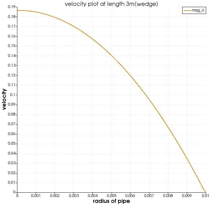
The maximum velocity obtained from the openfoam is 0.186581 where as the analytical maximum velocity obtained from matlab is 0.1875, the error is 0.000919
PRESSURE:
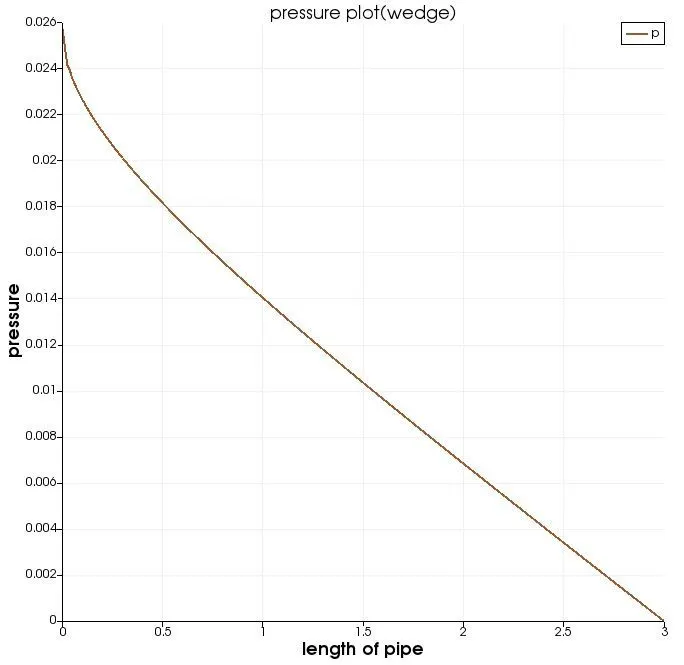
The pressure drop obtained from openfoam is 0.0257238 where as the analytical pressure drop obtained from matlab is 0.0201, the error is 0.0056238
Symmetric Boundary condition at 10 deg:
VELOCITY:
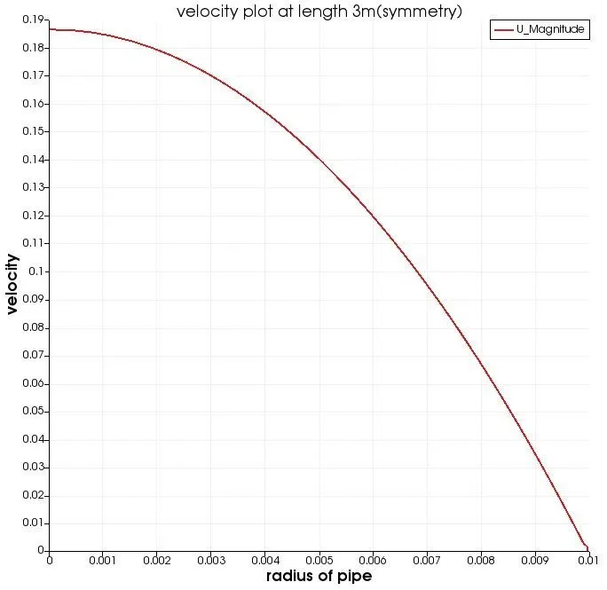
The maximum velocity obtained from the openfoam is 0.186582 where as the analytical maximum velocity obtained from matlab is 0.1875, the error is 0.000918
PRESSURE:
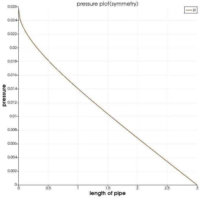
The pressure drop obtained from openfoam is 0.025718 where as the analytical pressure drop obtained from matlab is 0.0201, the error is 0.005618
Symmetric Boundary condition at 25 deg:
VELOCITY:
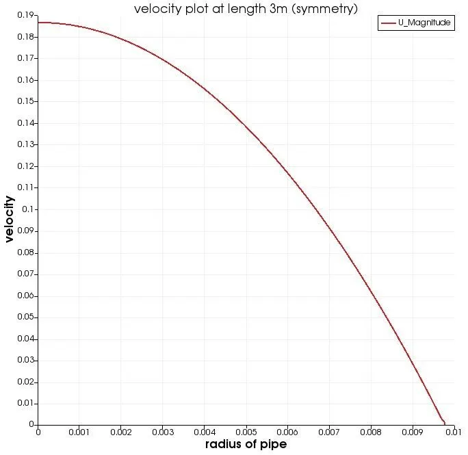
The maximum velocity obtained from the openfoam is 0.186692 where as the analytical maximum velocity obtained from matlab is 0.1875, the error is 0.000808
PRESSURE:
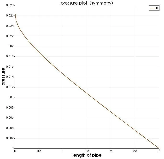
The pressure drop obtained from openfoam is 0.0265624 where as the analytical pressure drop obtained from matlab is 0.0201, the error is 0.0064624
Wedge Boundary condition at 25 deg:
VELOCITY:
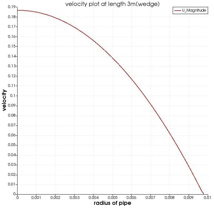
The maximum velocity obtained from the openfoam is 0.186692 where as the analytical maximum velocity obtained from matlab is 0.1875, the error is 0.000808
PRESSURE:
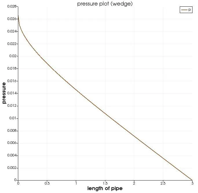
The pressure drop obtained from openfoam is 0.0265641 where as the analytical pressure drop obtained from matlab is 0.0201, the error is 0.0064641
Wedge Boundary condition at 45 deg:
VELOCITY:
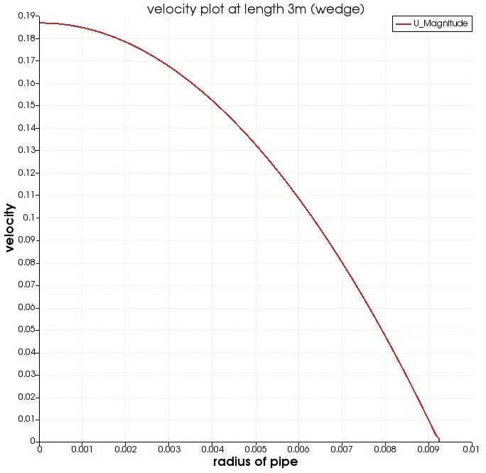
The maximum velocity obtained from the openfoam is 0.186919 where as the analytical maximum velocity obtained from matlab is 0.1875, the error is 0.000581
PRESSURE:
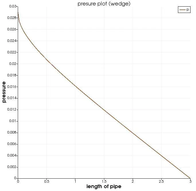
The pressure drop obtained from openfoam is 0.0290388 where as the analytical pressure drop obtained from matlab is 0.0201, the error is 0.0.0089388
Symmetric Boundary condition at 45 deg:
VELOCITY:
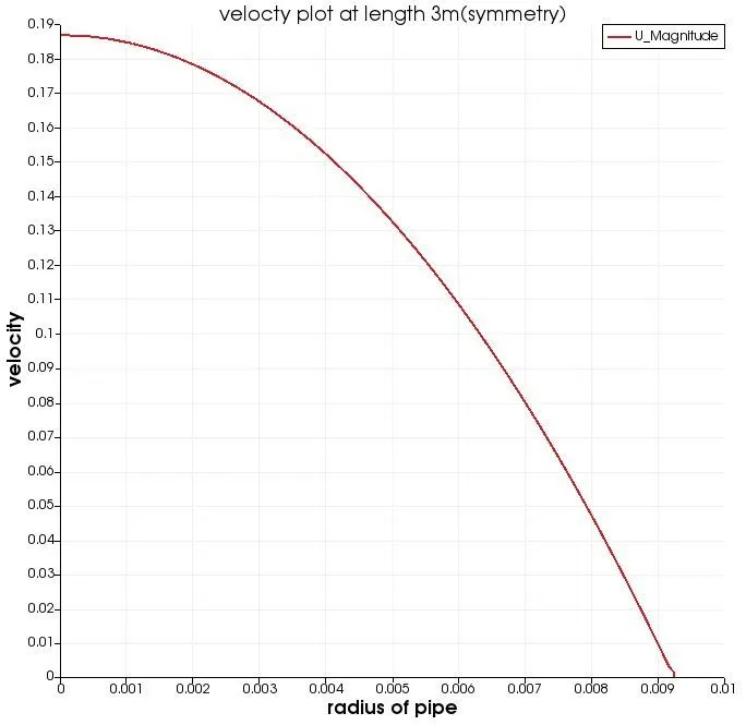
The maximum velocity obtained from the openfoam is 0.186919 where as the analytical maximum velocity obtained from matlab is 0.1875, the error is 0.000581
PRESSURE:
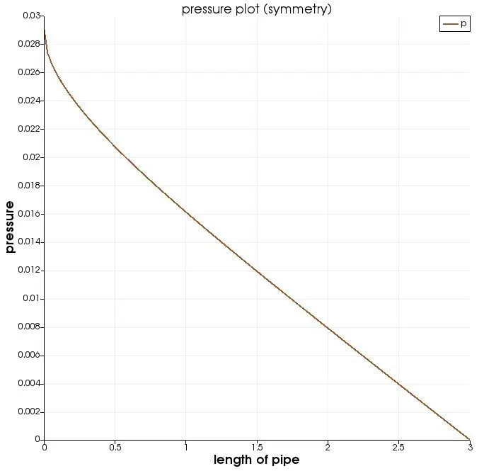
The pressure drop obtained from openfoam is 0.0290308 where as the analytical pressure drop obtained from matlab is 0.0201, the error is 0.0089308
Shear Stress with respect to the Radius of the pipe
Wedge Boundary condition at 10 deg:
SHEAR STRESS:
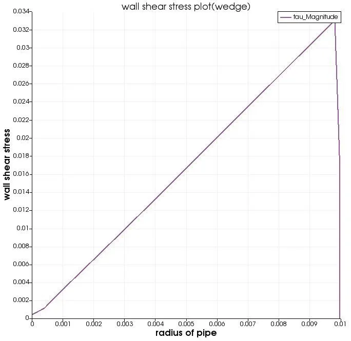
The maximum wall shear stress obtained from openfoam is 0.0329091 where as the analytical maximum shear stress obtained from matlab is 0.0334, the error is 0.000490
Symmetric Boundary condition at 10 deg:
SHEAR STRESS:
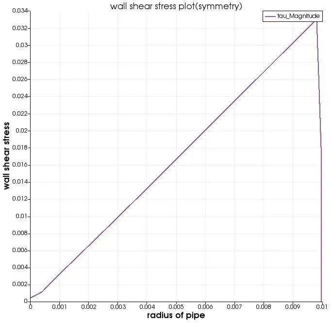
The maximum wall shear stress obtained from openfoam is 0.032909 where as the analytical maximum shear stress obtained from matlab is 0.0334, the error is 0.000491
Wedge Boundary condition at 25 deg:
SHEAR STRESS:
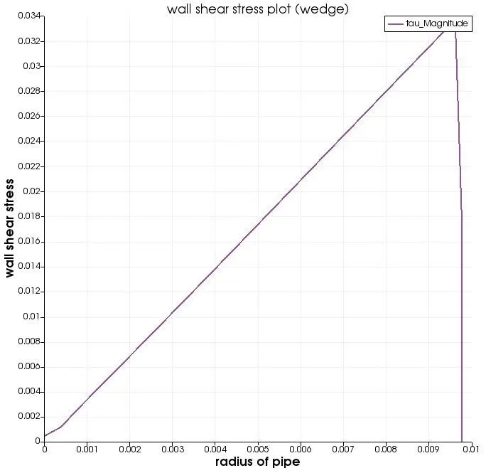
The maximum wall shear stress obtained from openfoam is 0.0336332 where as the analytical maximum shear stress obtained from matlab is 0.0334, the error is 0.000233
Symmetric Boundary condition at 25 deg:
SHEAR STRESS:
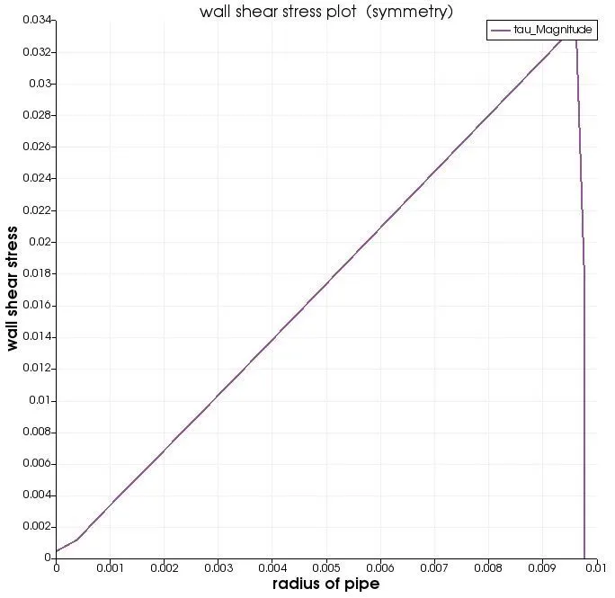
The maximum wall shear stress obtained from openfoam is 0.0336332 where as the analytical maximum shear stress obtained from matlab is 0.0334, the error is 0.0002332
Wedge Boundary condition at 45 deg:
SHEAR STRESS:
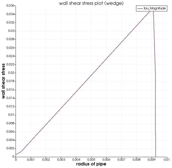
The maximum wall shear stress obtained from openfoam is 0.0354713 where as the analytical maximum shear stress obtained from matlab is 0.0334, the error is 0.0020713.
Symmetric Boundary condition at 45 deg:
SHEAR STRESS:
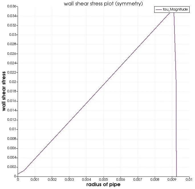
The maximum wall shear stress obtained from openfoam is 0.0352642 where as the analytical maximum shear stress obtained from matlab is 0.0334, the error is 0.0018642
| ANGLES | Max.Velocity (OPENFOAM) | percentage error of max.Velocity |
| Angle = 10 degree (wedge BC) | 0.186581 | 0.000919 |
| Angle = 10 degree (symmetry BC) | 0.186582 | 0.000918 |
| Angle = 25 degree (wedge BC) | 0.186692 | 0.000808 |
| Angle = 25 degree (symmetry BC) | 0.186692 | 0.000808 |
| Angle = 45 degree (wedge BC) | 0.186919 | 0.000581 |
| Angle = 45 degree (symmetry BC) | 0.186919 | 0.000581 |
By comparing both the results with symmetric and wedge boundary conditions at all degree, the error obtained using symmetric boundary condition is less compared with using of wedge boundary condition. As the angle increases the velocity increases with decrease in error
The differences in both boundary conditions in terms of their usage and application:
- In the increase of wedge angle, by using of symmetric boundary conditions the error in primitive variables is less compared to using of wedge boundary condition.
- The execution time for wedge boundary condition is higher compared to symmetric boundary condition.
- In the increase in wedge angle, the error in maximum velocity gets decreased in both wedge and symmetric boundary conditions.
- The application of symmetric boundary conditions is done all the mirror planes
- The application of wedge boundary condition is done only axi symmetric planes.
CONCLUSION:
- Validation is done for studies of Symmetry BC vs Wedge BC in OpenFOAM vs Analytical H.P equation for flow along a pipe using OpenFOAM.
- Validation is done for Hydro-dynamic length with the numerical result
- Validation is done for the fully developed flow velocity profile with its analytical profile
- Validation is done for maximum velocity and pressured drop for fully developed flow
- Validation is done for wall shear stress for fully developed flow
- Explained the differences in both boundary conditions in terms of their usage and application