Week 9 - Parametric study on Gate valve.
AIM:
Perform a parametric study on the gate valve simulation by setting the opening from 10 % to 80%.
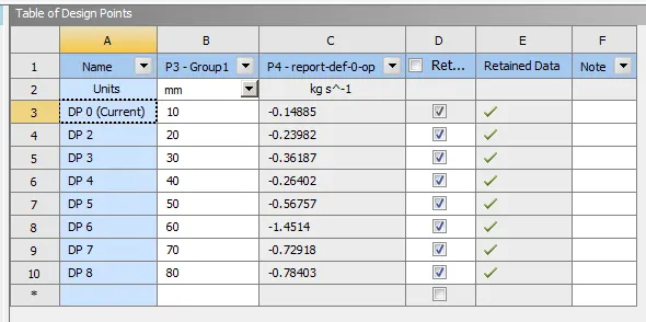
- Obtain the mass flow rates at the outlet for each design point.
- Calculate the flow coefficient and flow factor for each opening and plot the graph.
- Discuss the results of the mass flow rate and flow coefficient.
INTRODUCTION:
A gate valve, also known as a sluice valve, is a valve that opens by lifting a barrier (gate) out of the path of the fluid. Gate valves require very little space along the pipe axis and hardly restrict the flow of fluid when the gate is fully opened. The gate faces can be parallel but are most commonly wedge-shaped (to be able to apply pressure on the sealing surface).
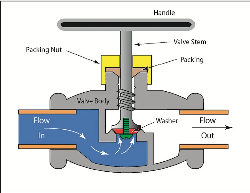
Common gate valves are actuated by a threaded stem that connects the actuator (e.g. handwheel or motor) to the gate. They are characterized as having either a rising or a non-rising stem, depending on which end of the stem is threaded. Rising stems are fixed to the gate and rise and lower together as the valve is operated, providing a visual indication of valve position. The actuator is attached to a nut that is rotated around the threaded stem to move it. Non-rising stem valves are fixed to, and rotate with, the actuator, and are threaded into the gate. They may have a pointer threaded onto the stem to indicate valve position since the gate's motion is concealed inside the valve. Non-rising stems are used where vertical space is limited.
Uses:
- Gate valves are used to shut off the flow of liquids rather than for flow regulation. When fully open, the typical gate valve has no obstruction in the flow path, resulting in very low flow resistance. The size of the open flow path generally varies in a nonlinear manner as the gate is moved. This means that the flow rate does not change evenly with stem travel. Depending on the construction, a partially open gate can vibrate from the fluid flow.
- Gate valves are mostly used with larger pipe diameters (from 2" to the largest pipelines) since they are less complex to construct than other types of valves in large sizes.
- Gate valves without an extra sealing ring on the gate or the seat are used in applications where minor leaking of the valve is not an issue, such as heating circuits or sewer pipes.
- Generally in pipelines with high pressure, the gate valve opening can be quite difficult due to the high force exerted on the gate. So they are generally connected with a smaller bypass valve to release the pressure and then they are operated.
PROCEDURE:
GEOMETRY:
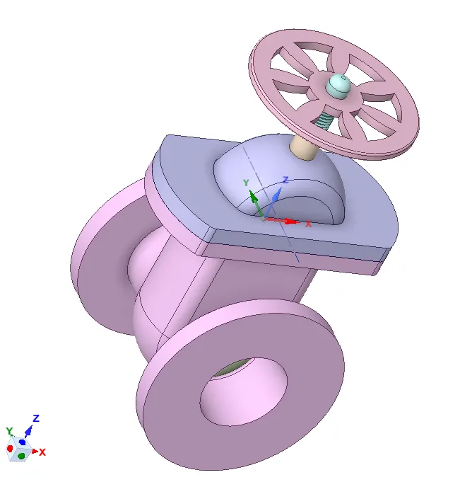
- Importing geometry in SpaceClaim The following geometry was imported into SpaceClaim.
-
It has the following components:
- The bonnet is placed below the handwheel and prevents the splashing of fluid from the upper region.
- Handwheel and spindle that can be used to lift or lower the gate disc.
- The gate disc is attached to the spindle at the bottom.
- The bottom is a casing that covers the gate disc and the water flows through it. Two ports serve as an inlet and outlet for the fluid.
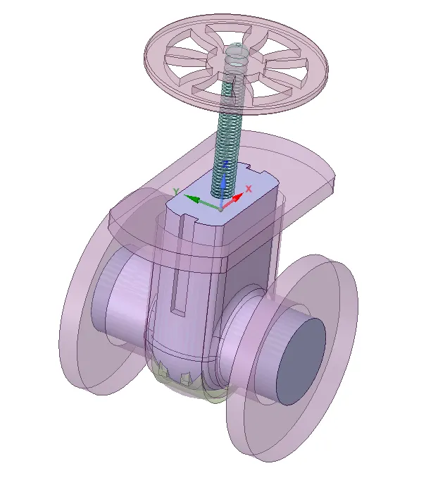
- To perform the parameterization, Disable all the solid components except the gate dic and spindle
- Go to the design tab and choose the move option and further select move body option and further select the gate disc.Following you will be able to see the coordinate system appear the gate disc,you can then proceed to move the gate disc towards the top of the spindle.
- The create parameter option doesnot appear along the dimension of the lift the alternate way to parametrize the same is to go to the groups menu which is adjacent to the structured menu, in the group menu you will able to see the create parameter button,which will be enabled only after you have move the gate disc.
- click on create parameter following which you will you see a group 1 appear in which you can edit the dimensions of the lift.This will parameterise your gate disc lift,you can confirm the same by checking your workbench.
-
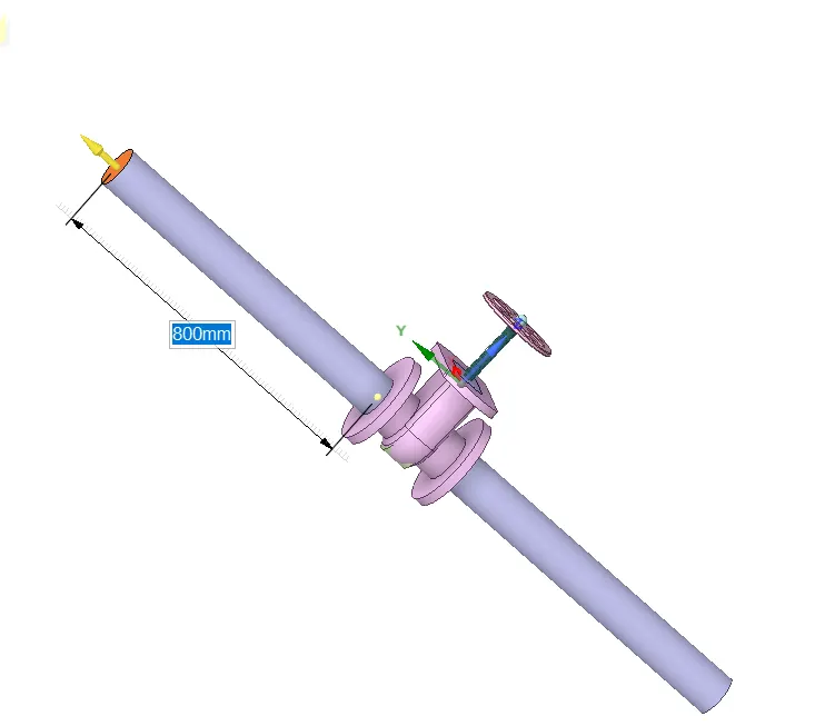
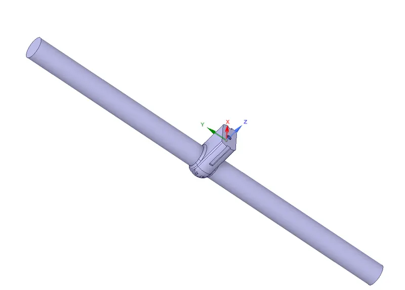
Extract the fluid volume.
Prepare > volume extract > select edges > press green tick symbol.
MESHING:
- Open the mesh console.
- For the mesh size choose mesh element size = 10mm >> click on generate mesh
- Give Name selection
SETUP:
| SOLVER TYPE | PRESSURE BASED |
| SOLVER TIME | STEADY STATE |
| GRAVITY | ON( Z AXIS AS -9.81m/s^2) |
| VISCOUS MODEL | K-EPSILON+REALIZABLE+SWIRL FLOW +SCALABLE WALL FUNCTIONS |
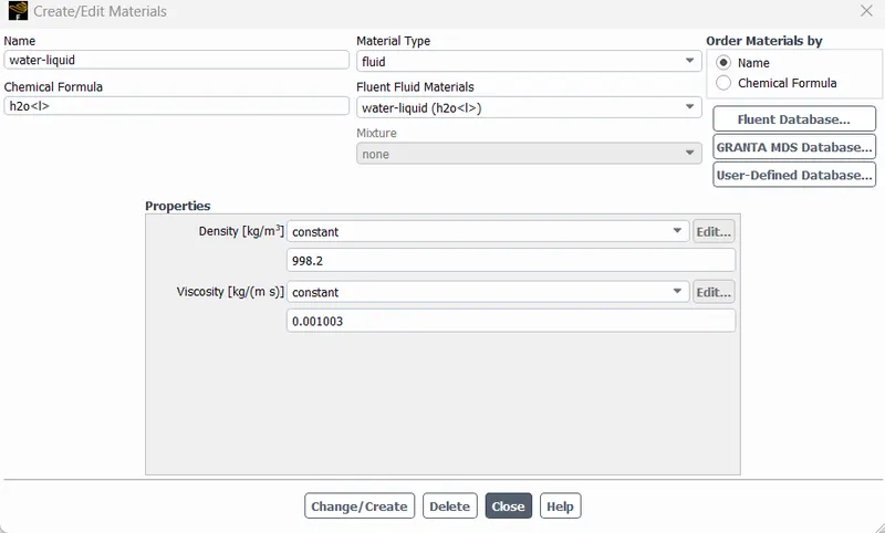
| MATERIAL | WATER(LIQUID) |
| METHOD | COUPLED |
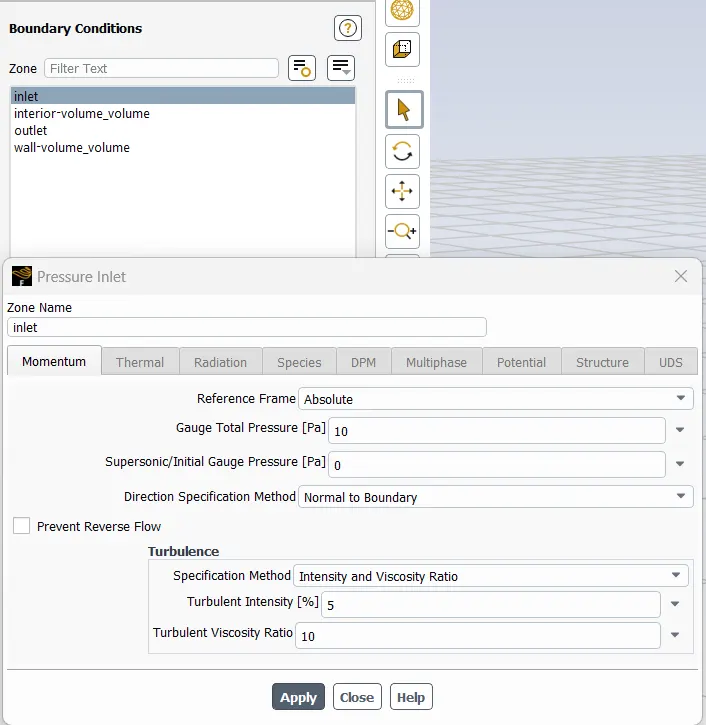
| INLET(PRESSURE INLET) | 10 Pa |
| OUTLET | PRESSURE OUTLET( 0 Pa) |
Perform general setup such as solver time as steady state, solver time as pressure based and enable gravity. 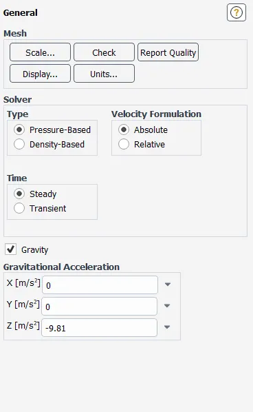
- Use Material as water
- Use viscous model as k-epsilon realizable swirl scalable.
- Create the plot for the mass flow rate at outlet and parametrise it to view the results in the project schematic window.
- Create the plot for the pressure at outlet and do parametrise it.
- set the boundary conditions. select inlet boundary selection as pressure inlet.
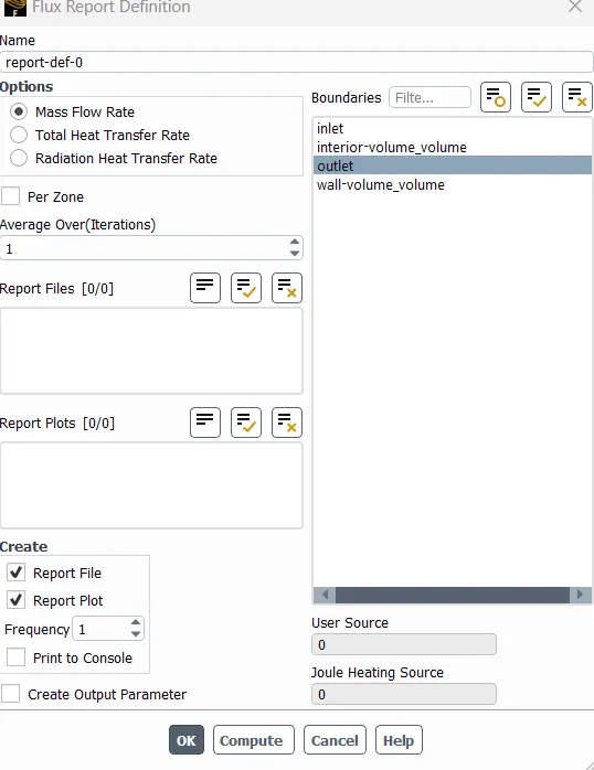
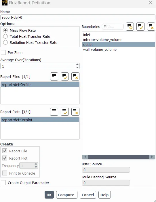
The velocity in y-direction is 0.1415488 m/s.
The Reynolds Number is calculated using the following formula:
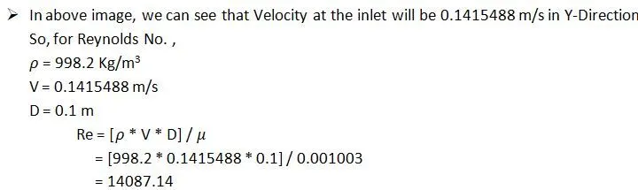
- From these calculations, the Reynolds Number appears to be greater than 2000 hence the adequate viscous model to be used is k-Ꜫ model.
- Initialize the problem using standard initialization.
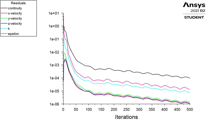
- Run the simulation for 500 iterations.
CASE1:
GATE DISC OPENING IS 10mm.
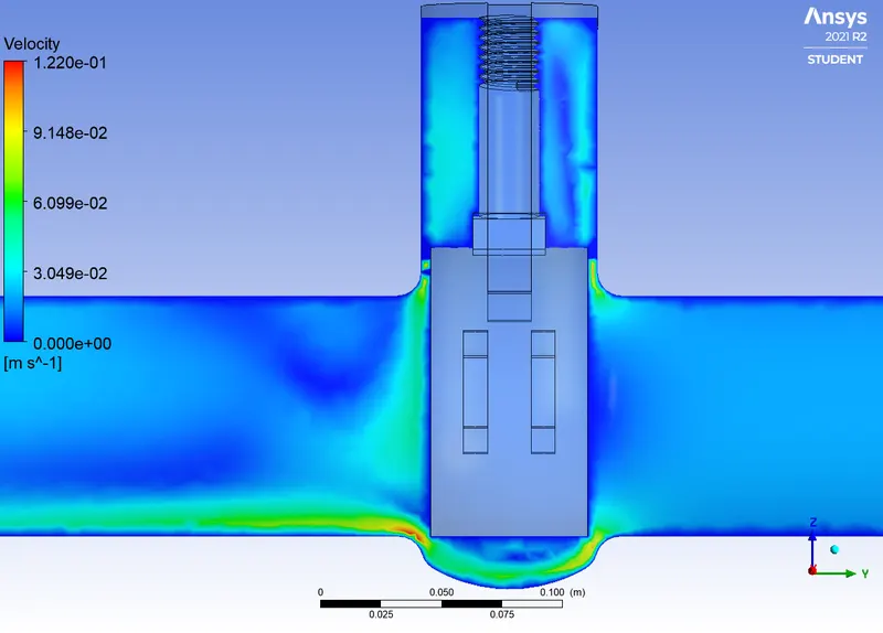
RESIDUAL PLOT:

Mass Flow rate:
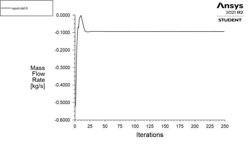
In physics and engineering, mass flow rate is the mass of a substance which passes per unit of time. Its unit is kilogram per second in SI units, and slug per second or pound per second in second in US customary units. Mass flow rate is defined by the limit:
ṁ=dm/dtṁ
Flow Coefficient:
The flow coefficient of a device is a relative measure of its efficiency at allowing fluid flow. It describes the relationship between the pressure dop across an orifice valve or other assembly and the corresponding flow rate.
Mathematically the flow coefficient Cv is expressed as:
Cv=Q√(SG/ΔP)
Where
Q is the rate of flow (expressed in US gallons per minute),
SG is the specific gravity of the fluid (for water=1);
∆P is the pressure drop across the valve (expressed in psi)
Flow Factor:
Flow factor (Kv) is the flow coefficient in metric units that is defined as the flow rate in cubic meters per hour(m3/h) of water at a temperature of 16°C with a pressure drop across the valve or any other restricting device of 1 bar. The Kv is related to the head drop (∆h) or pressure drop (∆P) across the valve with the flow rate (Q).
Mathematically, the Flow Factor is given as:
Kv=0.865.Cv
Q = 0.14885 kg/s = 2.35932 gal/min
SG = 1000/998.2≈1
∆P= 0.0014241308
Cv=2.35932√(1/0.0014241308)
=62.519
Kv=0.865⋅Cv
=Kv=0.865x62.519
=54.0789
CASE 2:
Gate disc lift = 20 mm
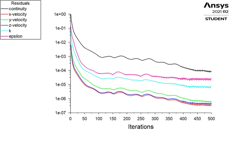
RESIDUAL PLOT:
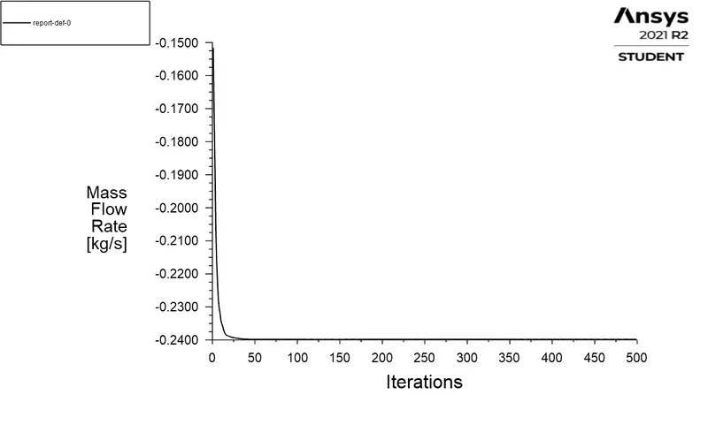
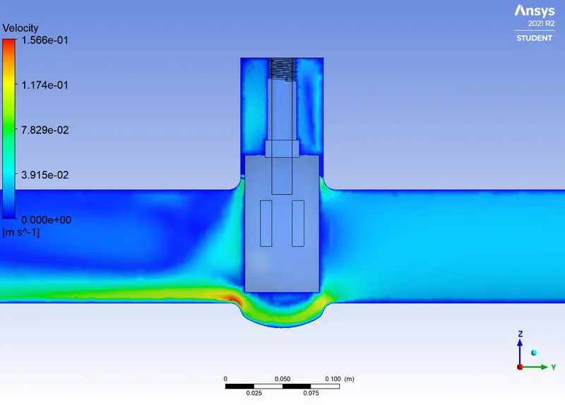

Q = 0.23982 Kg/s = 3.80122 gal/min
SG = 1000/998.2≈1
∆P= 0.0013822448
Cv=3.80122√(1/0.0013822448)
=102.242
Kv=0.865⋅Cv
Kv=0.865x102.242
=88.4393
CASE 3:
Gate disc lift = 30 mm
RESIDUAL PLOT:
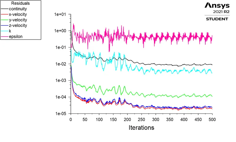
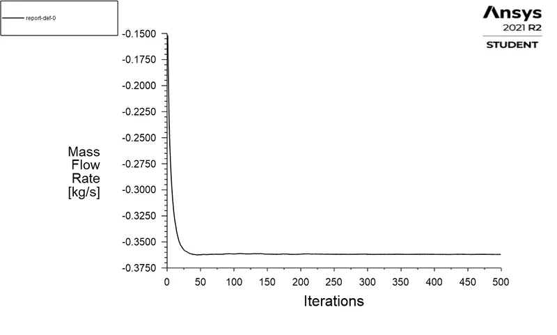
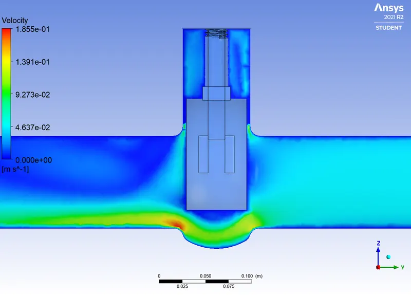

Q = 0.36187 Kg/s = 5.73576 gal/min
SG = 1000/998.2≈1
∆P= 0.001295168
Cv=5.73576√(1/0.001295168)
=159.378
Kv=0.865⋅Cv
Kv=0.865x159.378
=137.862
CASE 4:
Gate disc lift = 40 mm
RESIDUAL PLOT:
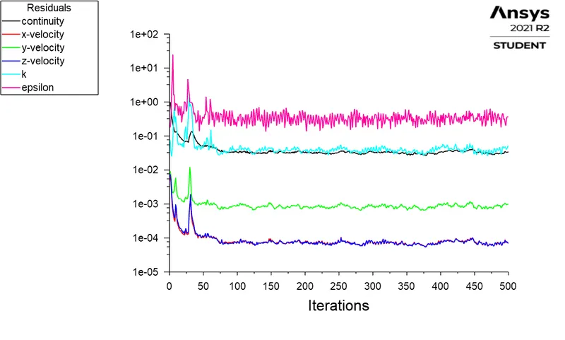
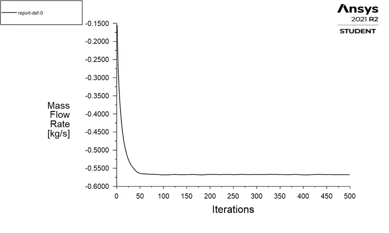
Q = 0.56757 Kg/s = 8.99617 gal/min
SG = 1000/998.2≈1
∆P= 0.00106843
Cv=8.99617√(1/0.00106843)
=275.223
Kv=0.865⋅Cv
Kv=0.865x275.223
=238.068
CASE 5:
Gate disc lift = 70 mm
RESIDUAL PLOT:
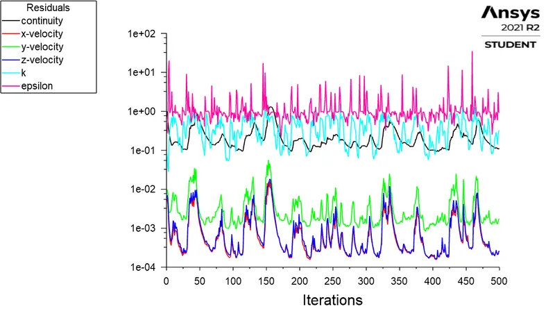
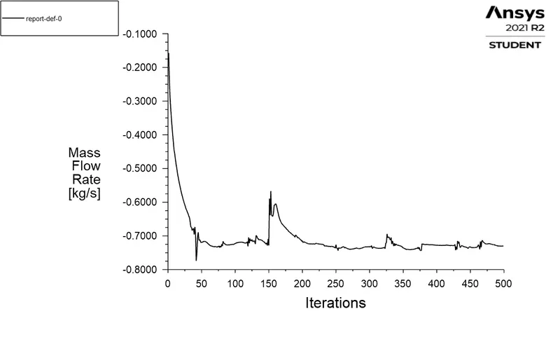
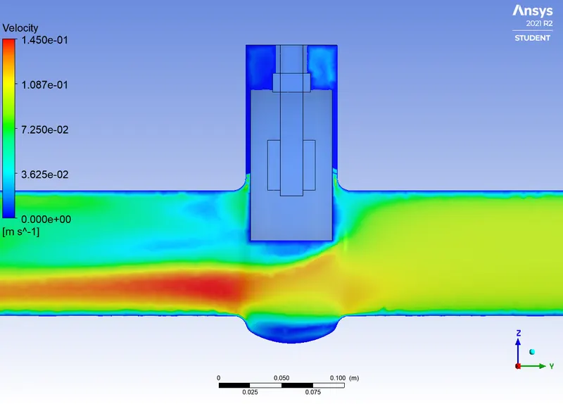

Q = 0.72918 Kg/s = 11.55774 gal/min
SG = 1000/998.2≈1
∆P= 0.000818448
Cv=11.55774√(1/0.000818448)
=403.996
Kv=0.865⋅Cv
Kv=0.865x403.996
=349.457
CASE 5:
Gate disc lift = 80 mm
RESIDUAL PLOT:
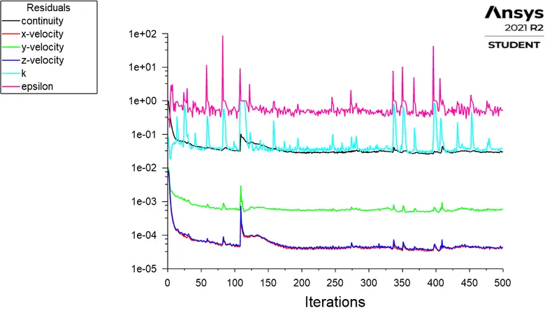
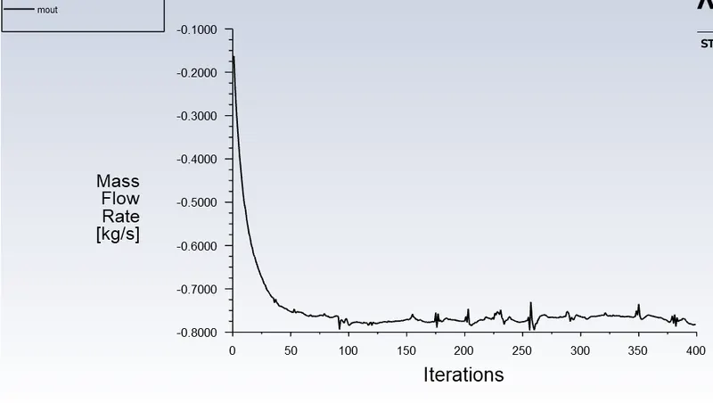
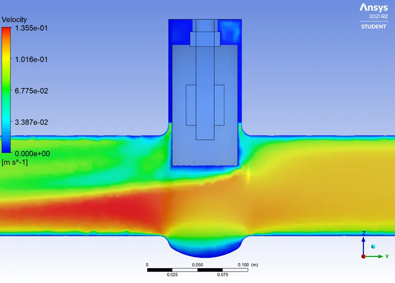

Q = 0.78403 Kg/s = 12.42713 gal/min
SG = 1000/998.2≈1
∆P= 0.0007218264
Cv=12.42713√(1/0.0007218264)
=462.546
Kv=0.865⋅Cv
Kv=0.865x462.546
=400.102
|
Case |
Mass Flow Rate (kg/S) |
Gate Disc lift (mm) |
Flow Coefficient |
Flow Factor |
|
1 |
2.35932 |
10 |
62.519 |
54.0789 |
|
2 |
3.80122 |
20 |
102.242 |
88.4393 |
|
3 |
5.73576 |
30 |
159.378 |
137.862 |
|
4 |
8.99617 |
50 |
275.223 |
238.068 |
|
5 |
11.55774 |
70 |
403.996 |
349.457 |
|
6 |
12.42713 |
80 |
462.546 |
400.102 |
From the above results, we clearly see that the mass flow rate increases with the gate disc lift or opening. The same thing happens with the flow coefficient and the flow factor as the mass flow rate increases. Broadly, the mass flow rate, the flow coefficient and the flow factor vary linearly with the gate disc opening.
Conclusion:
- Flow-coefficient and flow-factor increase with increasing opening percentage.
- Differential pressure across the gate valve decreases with increasing opening percentage. This is because there is less blockage to the flow.
- Mass-flow rate and velocity increase with increasing opening percentage. This is because there are more pathways for the water to flow.
- Gate valve should operate in a fully-opened or fully-closed position. A partially-opened valve induces vibration which can damage the gate valve.
- Also the gate valve should be closed gradually rather than suddenly, as it causes a water hammer effect which can again damage the gate valve.