Week-6 : Turbocharger Modelling
AIM:
- To List down different TC and locate examples from GT Power
- To Explore tutorial number 6 and 7
- To Plot operating points on compressor and turbine maps
- To explain in which application Variable Geometry Turbine is beneficial?
- To Explore example- Diesel VGT EGR and understand the modeling part.
PROCEDURE:
List down different TC and locate examples from GT Power.
Turbocharger:
A turbocharger (technically a turbocharger), colloquially known as turbo, is a turbine-driven, forced – induction device that increases an internal combustion engine power output by forcing extra compressed air into the combustion chamber. This improvement over a naturally aspirated engine power output is because the compressor can force more air—and proportionately more fuel—into the combustion chamber than atmospheric pressure.
In naturally aspirated piston engines, intake gases are drawn or "pushed" into the engine by atmospheric pressure filling the volumetric void caused by the downward stroke of the piston (which creates a low-pressure area), similar to drawing liquid using a syringe. The amount of air actually drawn in, compared with the theoretical amount if the engine could maintain atmospheric pressure, is called volumetric efficiency. The objective of a turbocharger is to improve an engine's volumetric efficiency by increasing density of the intake gas (usually air) allowing more power per engine cycle.
The turbocharger's compressor draws in ambient air and compresses it before it enters into the intake manifold at increased pressure. This results in a greater mass of air entering the cylinders on each intake stroke. The power needed to spin the centrifugal compressor is derived from the kinetic energy of the engine's exhaust gases.
In automotive applications, 'boost' refers to the amount by which intake manifold pressure exceeds atmospheric pressure at sea level. This is representative of the extra air pressure that is achieved over what would be achieved without the forced induction. The level of boost may be shown on a pressure gauge, usually in bar, psi or possibly kPa. The control of turbocharger boost has changed dramatically over the 100-plus years of their use. Modern turbochargers can use waste gates, blow-off valves and variable geometry.
Types of turbocharger:
- Single turbo
- Twin turbo
- Variable geometry turbo
- Variable twin scroll turbo
- Electric turbo.
Single turbo:
Single turbochargers alone have limitless variability. Differing the compressor wheel size and turbine will lead to completely different torque characteristics. Large turbos will bring on high top-end power, but smaller turbos will provide better low-end grunt as they spool faster. There are also ball bearing and journal bearing single turbos. Ball bearings provide less friction for the compressor and turbine to spin on, thus are faster to spool (while adding cost).
Advantages:
- Cost effective way of increasing an engine’s power and efficiency.
- Simple, generally the easiest of the turbocharging options to install.
- Allows for using smaller engines to produce the same power as larger naturally-aspirated engines, which can often remove weight.
Disadvantages:
- Single turbos tend to have a fairly narrow effective RPM range. This makes sizing an issue, as you’ll have to choose between good low-end torque or better high-end power.
- Turbo response may not be as quick as alternative turbo setups.
Twin scroll turbo:
Twin-scroll turbochargers are better in nearly every way than single-scroll turbos. By using two scrolls, the exhaust pulses are divided. For example, on four cylinder engines (firing order 1-3-4-2), cylinders 1 and 4 might feed to one scroll of the turbo, while cylinders 2 and 3 feed to a separate scroll. Why is this beneficial? Let’s say cylinder 1 is ending its power stroke as the piston approaches bottom dead centre, and the exhaust valve starts to open. While this is happening, cylinder 2 is ending the exhaust stroke, closing the exhaust valve and opening the intake valve, but there is some overlap. In a traditional single-scroll turbo manifold, the exhaust pressure from cylinder 1 will interfere with cylinder 2 pulling in fresh air since both exhaust valves are temporarily open, reducing how much pressure reaches the turbo and interfering with how much air cylinder 2 pulls in. By dividing the scrolls, this problem is eliminated.
Advantages:
- More energy is sent to the exhaust turbine, meaning more power.
- A wider RPM range of effective boost is possible based on the different scroll designs.
- More valve overlap is possible without hampering exhaust scavenging, meaning more tuning flexibility.
Disadvantages:
- Requires a specific engine layout and exhaust design (eg: I4 and V8 where 2 cylinders can be fed to each scroll of the turbo, at even intervals).
- Cost and complexity versus traditional single turbo.
Variable geometry turbocharger (VGT):
Perhaps one of the most exceptional forms of turbocharging, VGTs are limited in production (though fairly common in diesel engines) as a result of cost and exotic material requirements. Internal vanes within the turbocharger alter the area-to-radius (A/R) ratio to match the RPM. At low RPM, a low A/R ratio is used to increase exhaust gas velocity and quickly spool up the turbocharger. As the revs climb, the A/R ratio increases to allow for increased airflow. The result is low turbo lag, a low boost threshold, and a wide and smooth torque band.
Advantages:
- Wide, flat torque curve. Effective turbocharging at a very wide RPM range.
- Requires just a single turbo, simplifying a sequential turbo setup into something more compact.
Disadvantages:
- Typically only used in diesel applications where exhaust gases are lower so the vanes will not be damaged by heat.
- For gasoline applications, cost typically keeps them out as exotic metals have to be used in order to maintain reliability. The tech has been used on the Porsche 997, though very few VGT gasoline engines exist as a result of the cost associated.
Variable twin scroll turbocharger:
It combines the advantages of a twin scroll turbo and a variable geometry turbo. It does this by the use of a valve which can redirect the exhaust airflow to just a single scroll, or by varying the amount the valve opens can allows for the exhaust gases to split to both scrolls. The VTS turbocharger design provides a cheaper and more robust alternative to VGT turbos, it means it is a viable option for petrol engine applications. It allows for a wide flat torque curve. It is more robust in design versus a VGT, depending on the material selection.
Electric turbocharger:
Aeristech’s patented Full Electric Turbocharger Technology is a new enabling technology that will help vehicle manufacturers meet stringent future emissions legislation whilst providing excellent response throughout the engine operating range, even at low engine rpm and vehicle speed.FETT is the ultimate solution for extreme engine downsizing and improved engine efficiency using a single stage turbocharger.
Throwing a powerful electric motor in the mix eliminates nearly all of the drawbacks of a turbocharger. Turbo lag? Gone. Not enough exhaust gases? No problem. Turbo can’t produce low-end torque? Now it can! Perhaps the next phase of modern turbocharging, there are undoubtably drawbacks of the electric path as well.
GT-POWER EXAMPLES:
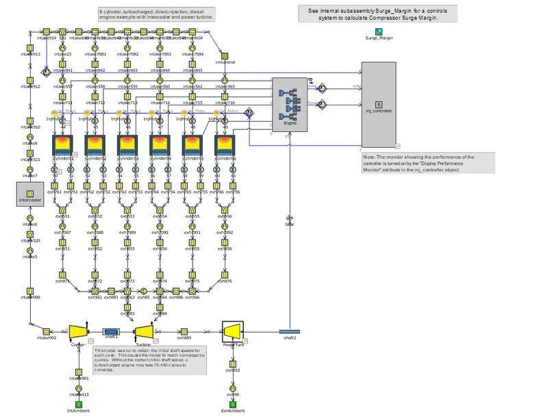
Normal turbocharger model:
Go to File-> Examples-> Engine_1D_Gas_Exchange_Combustion-> Diesel-> Diesel_6cyl_TC-> Diesel_6cyl_TC.gtm
VGT model:
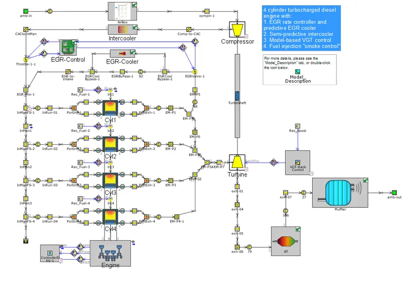
Go to File-> Examples-> Engine_1D_Gas_Exchange_Combustion-> Diesel->Diesel_VGT_EGR->Diesel_VGT_EGR.gtm
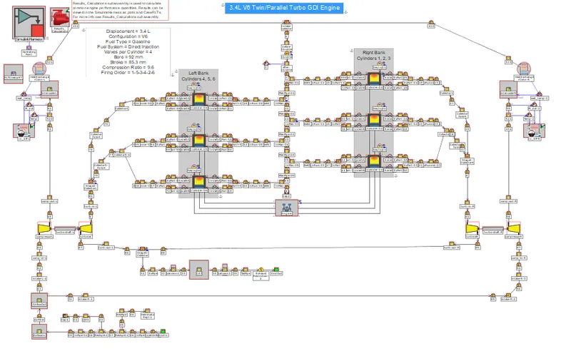
Twin-turbo model:
Go to File-> Examples->Engine_0D_SiL_and_HiL->xRT-3pt4L-V6-TwinTurbo-GDI->xRT-3pt4L-V6-TwinTurbo-GDI.gtm
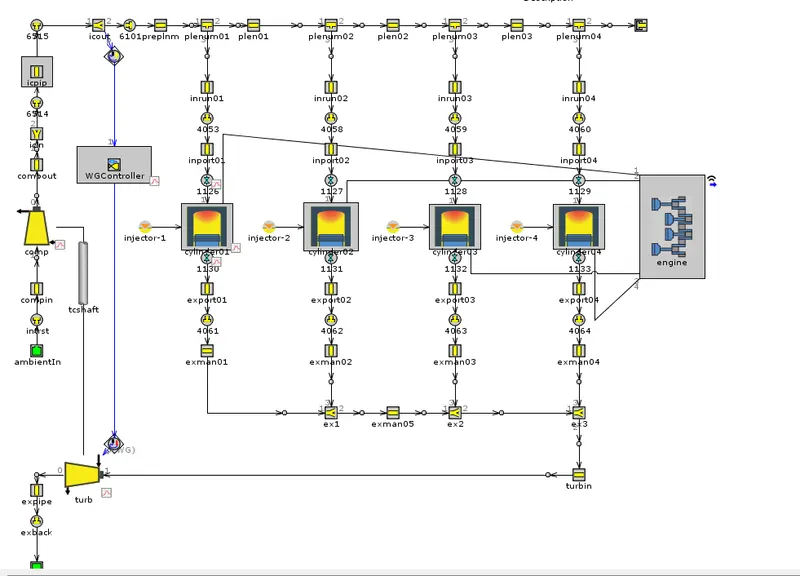
Waste gate model:
Go to File->Examples->Engine_1D_Gas_Exchange_Combustion->Diesel->Diesel_WGController
->Diesel_WGController.gtm
Explore tutorial number 6 and 7:
Tutorial 6:
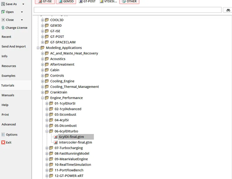
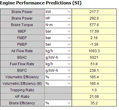
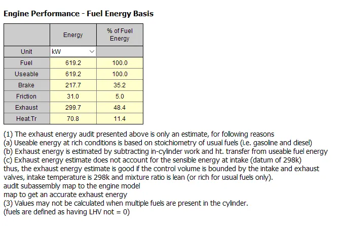
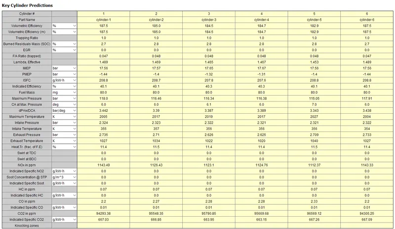
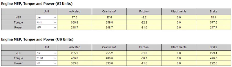
Go to File->Tutorials->Modeling_Applications->Engine_Performance->06-6cylDIturbo->6cylDI-final.gtm
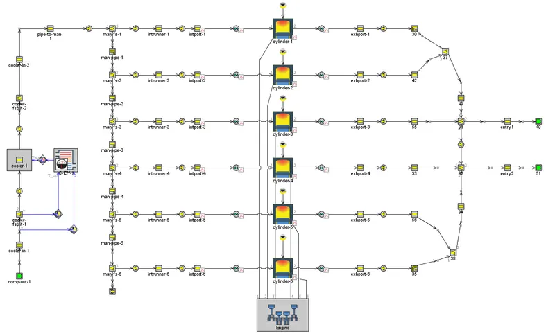
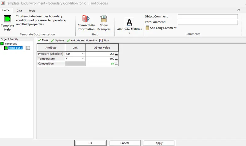
Pressure at compressor out is set:
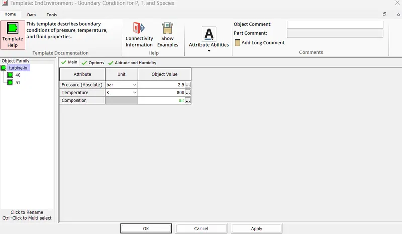
Pressure at turbine in is set:
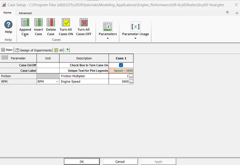
Case setup:
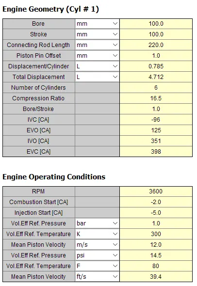
ENGINE GEOMETRY:
Tutorial 7:
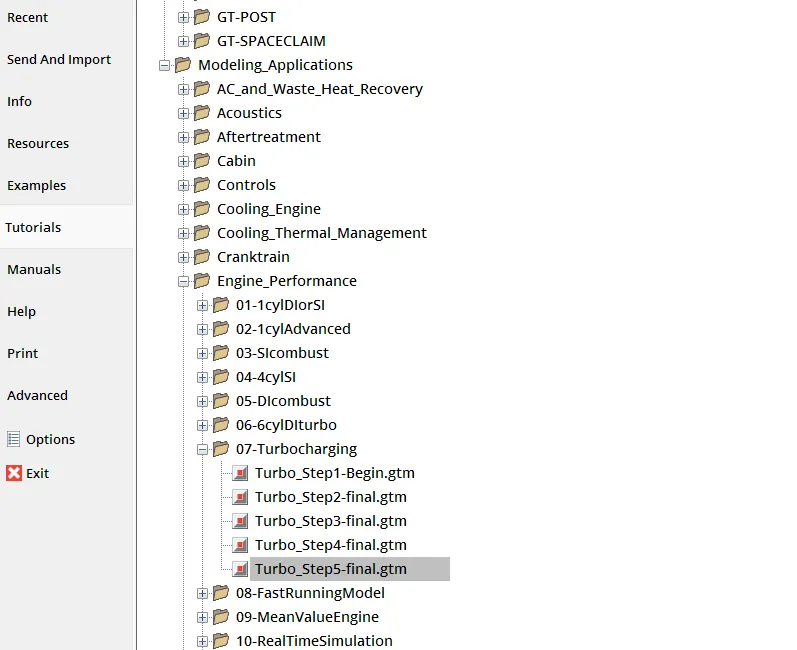
Go to File->Tutorials->Modeling_Applications->Engine_Performance->07-Turbocharging->Turbo_Step5-final.gtm
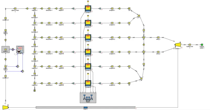
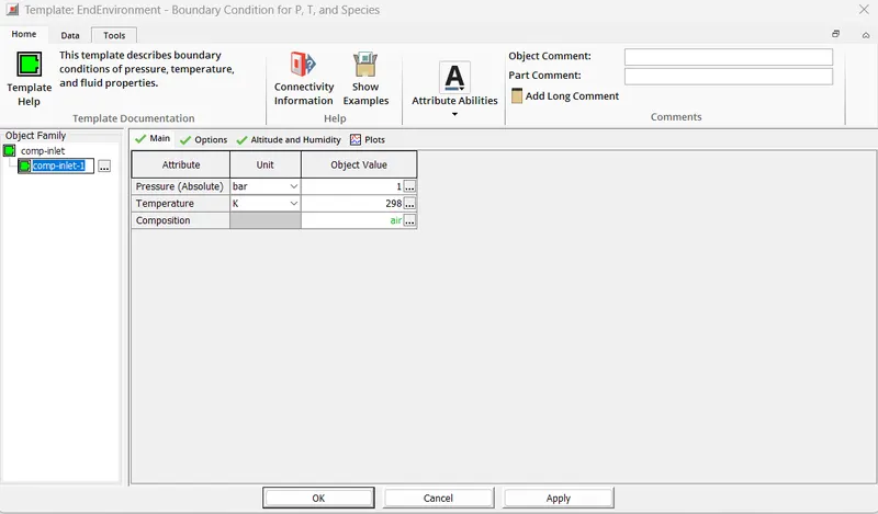
Pressure at compressor inlet is set:
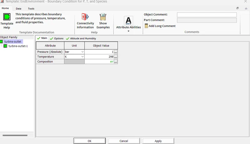
Pressure at turbine outlet is set:
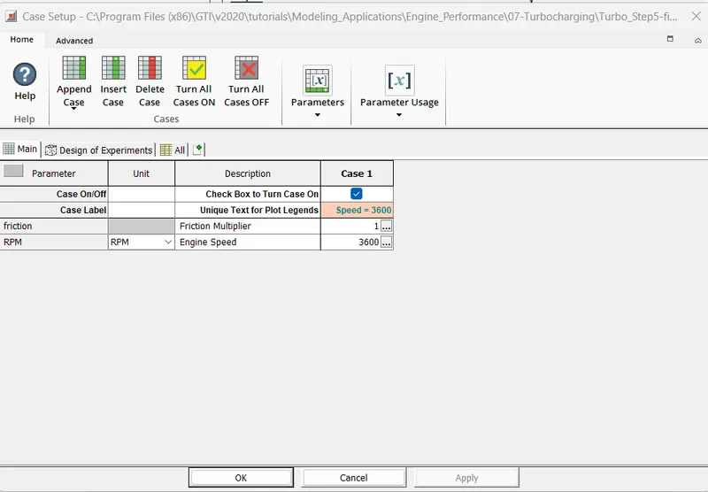
Case setup:
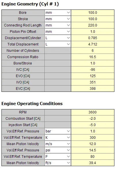
ENGINE GEOMETRY:
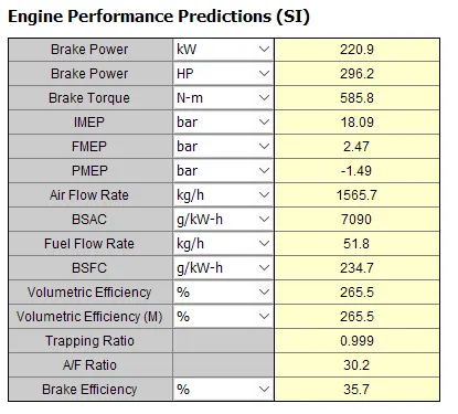
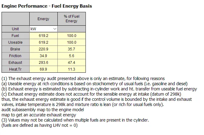
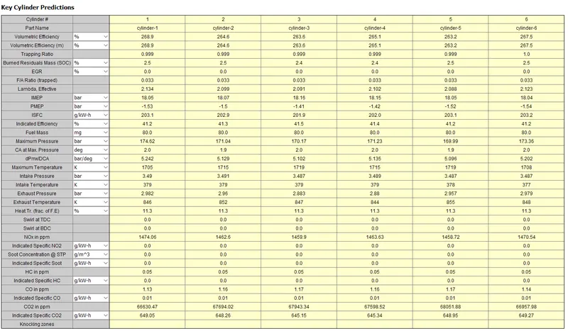
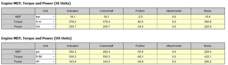
PLOT OPERATING POINTS ON COMPRESSOR AND TURBINE MAPS:
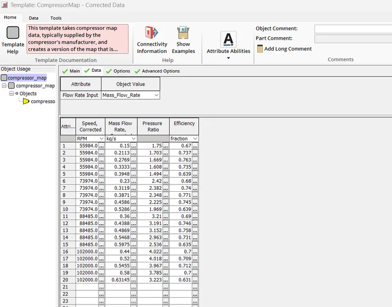
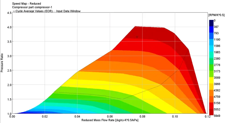
COMPRESSOR MAP:
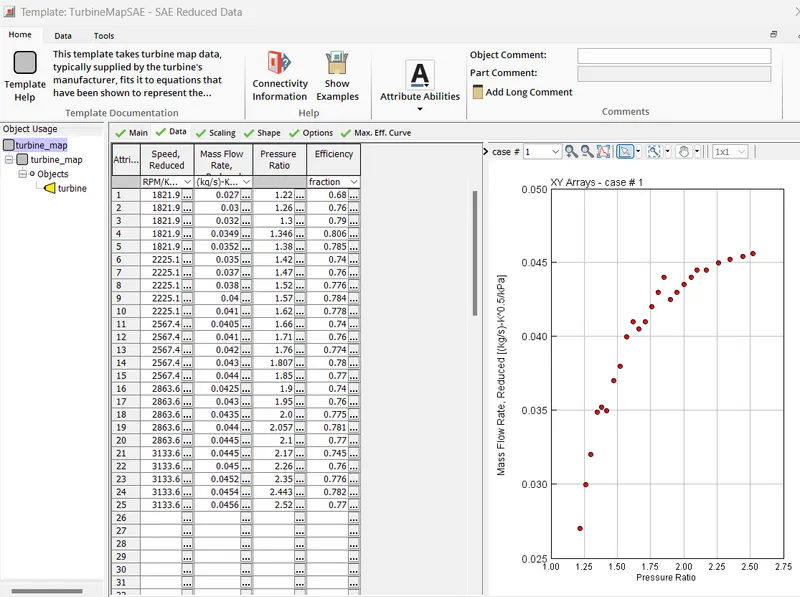
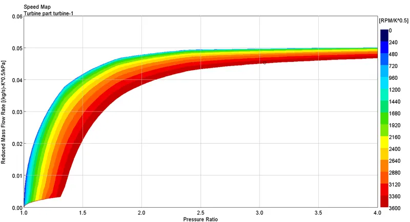
We have used tutorial 7 to plot the operating points on compressor and turbine map
PLOTTING POINTS:
TURBINE MAP:
PLOTTING POINTS:
In which application Variable Geometry Turbine is beneficial?
VGT turbocharger were used for particularly diesel engine applications as they were operational only on low exhaust gas temperature. But, due to the advancement in the materials which have high thermal resistance, the VGT has been increasingly used in the gasoline engines.
The engineering applications where VGT have been a highly successful solution are:
- Passenger cars
- Race vehicles
- Light commercial vehicles
These applications have varied requirements at different engine speeds and VGT provides them the suitable solution as it provides high pressure boost at low speeds and lower turbo lag compared to its counterparts. Furthermore, at high engine speeds, it prevents overboosting thus has a direct impact on fuel economy. From this, we can conclude that VGT are an appropriate choice for applications which operates on long operating scale.
Explore example- Diesel VGT EGR and understand the modeling part
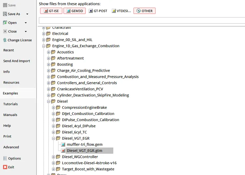
Go to File->Examples->Engine_1D_Gas_Exchange_Combustion->Diesel->Diesel_VGT_EGR
->Diesel_VGT_EGR.gtm
Working of a Diesel VGT EGR:
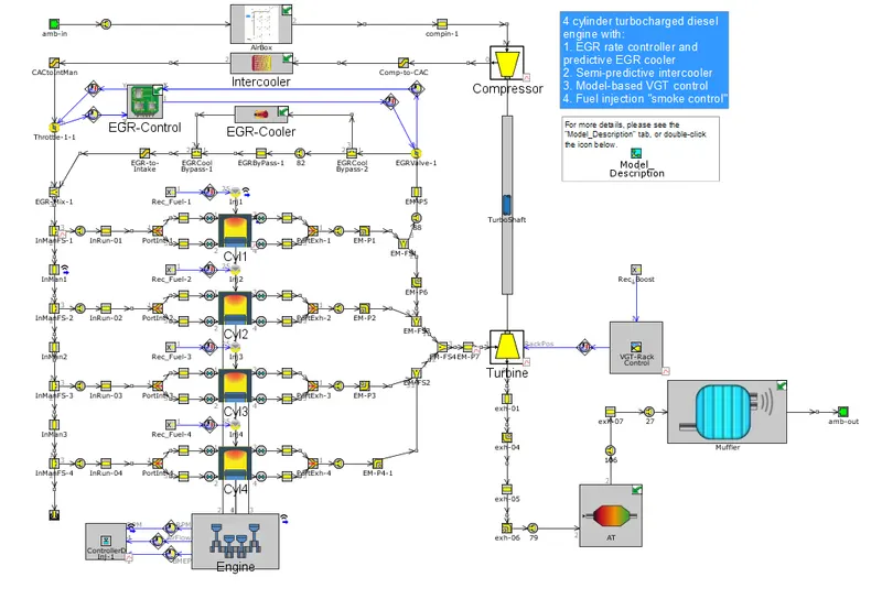
- This is a 4 cylinder and 16 valve engine with EGR cooler and VGT.
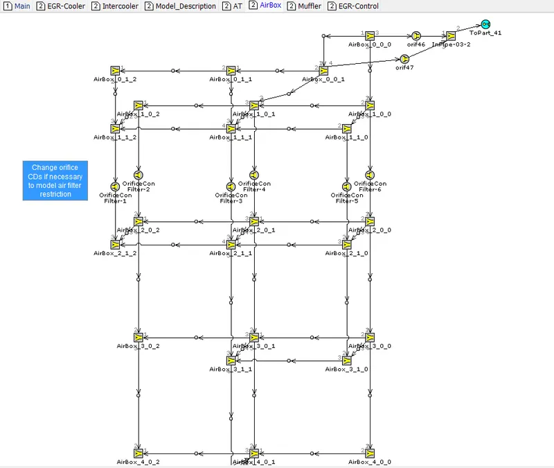
- The ambient air is sucked through the inlet and then the air is passed through the air filters where dirty air and dust particles can be purified and pure air passed into the compressor from compressor the compressed air is passes through the Intercooler.
- In the intercooler the temperature of the air is decreases and increases in the density of the air and thus we will have higher airflow rate than the flow rate of the Ambient air.
- The air from Intercooler passed through the throttle valve where air is passed through this if the throttle valve open means the drive inputs is 90 and if the throttle valve Close means the drive inputs is 0.
- From the throttle valve the air is passed through the two inlet ports into cylinder where combustion takes places during the Power stroke.
- During the exhaust Stroke the exhaust gases and air passes through the exhaust manifold from the exhaust manifold some of the air went to the turbine and some of air went through the Exhaust Gas Recirculation (EGR) in order to reduce the emissions of the NoX.
- The turbine and Compressor are connected to the single shaft from the turbine the air is passed through the wall flow filter (where the diesel and Gasoline particles filters) from there it passes through the Muffler and gases went into atmosphere through it.
The Engine:
- The engine is a 4-cylinder, four-stroke, direct injection, 2L diesel engine. The engine runs in "speed" mode, where the engine speed is entered by the user and the engine torque is calculated.
- Combustion is modeled by the DI Pulse method, a predictive combustion model using the detailed injection profiles. In-cylinder heat transfer is modeled using the Woschni model.
- A FE model is used to predict the cylinder, head and piston temperatures. This simulation will run until it reaches steady-state convergence for six different engine speeds at full load, three part load operating points, and an additional idle point (total of 10 cases).
The Intake System:
- The intake system consists of the air piping upstream of the compressor inlet, and contains a simple model of an air box. The air box is modeled as a group of interconnected flow splits that represent the total volume of the air box. At the inlet and outlet of the air box, "bell mouth" orifice connections are used to model smooth transitions.
The Intercooler:
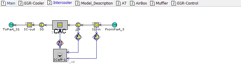
- The intercooler is found downstream of the compressor outlet. This intercooler is an air-to-air intercooler that is modeled using a "semi-predictive" method based on heat exchanger effectiveness.
- Note that if heat exchanger performance data is available, it is generally preferred to model the heat exchanger using 'Hx Master' and 'Hx Slave' parts (which will use the available data to create non-dimensional Nusselt correlations defining heat exchanger performance).
- This approach will generally extrapolate better than an assumed effectiveness to conditions beyond those present in the heat exchanger data. However, if heat exchanger data is not available (or if the simulation will be run at conditions where HX effectiveness is well known), the semi-predictive effectiveness method is appropriate
The Intake Manifold:
- The intake manifold is modeled as aluminium using heat conduction objects to calculate the wall temperatures. This is important in turbocharged models since wall temperatures may change substantially at different operating points, thus influencing the cylinder inlet temperature.
- The orifices that connect. The initial conditions are different from ambient conditions. The initial temperatures and pressures are specified at the expected boost pressure in order to decrease the convergence time.
The Fuel Injection System:
- The fuel is injected directly into the cylinders. Both the injection timing and the injection profile are looked up using an RLT Dependence' as a function of engine speed and injection rate. There is a simple control system that determines the total injected fuel mass (mg/stroke).
- This control system begins with a 'Signal Generator' part that imposes an accelerator pedal position input. The "requested fuel mass" is then looked up as a function of engine speed and pedal position. In some cases, the requested fuel mass may produce excess smoke if the boost pressure is not high enough to provide enough air. Therefore, the maximum allowed fuel mass is looked up as a function of the engine speed and the boost pressure.
- A 'Min Max' part is used to take the smaller of the requested fuel mass and the smoke limited fuel mass. This value is then imposed on the injectors using an actuator.
The Exhaust System:
- The Exhaust manifold is modelled as Cast iron using heat conduction objects to calculate the wall temperatures. This is very important in the exhaust manifold since wall temperatures change substantially between full load and idle condition, thus influencing the turbine inlet temperatures and turbine power.
- The orifices that connect the exhaust ports to the runners do not allow heat to be conducted between the pipe walls of the adjacent parts. This is necessary because the wall temperature is calculated in the exhaust pipes, while it has been imposed in the port (the imposed value is artificially high to account for heat transfer from the valve).
- The initial conditions are different from ambient conditions. The initial temperatures and pressures are specified at the expected backpressure in order to decrease the convergence time. The turbine part references a map file from which map data is read.
The EGR System:
- The model includes an exhaust gas recirculation (EGR) system to transport exhaust gases from the exhaust manifold back to the intake manifold. The EGR flow is driven by a positive pressure difference between the exhaust manifold and intake manifold and is controlled by an orifice connection (EGR-valve).
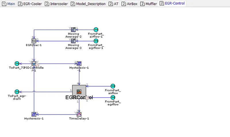
- The EGR-valve diameter is imposed by an actuator, and is determined automatically by an 'Controller EGR Valve' part to achieve a target EGR fraction. The desired EGR fraction is mapped as a function of engine speed and the requested BMEP. EGR rates in the model are as high as 40% at some operating points. Because of the high EGR rates, it is desirable to cool the EGR gases using a heat exchanger (EGR-cooler).
- When the pressure drop across the EGR system is not sufficient to achieve the target EGR rate, a throttle in the intake system, controlled by a PID controller, increases the pressure difference. This controller is only active, if the EGR-valve is fully open.
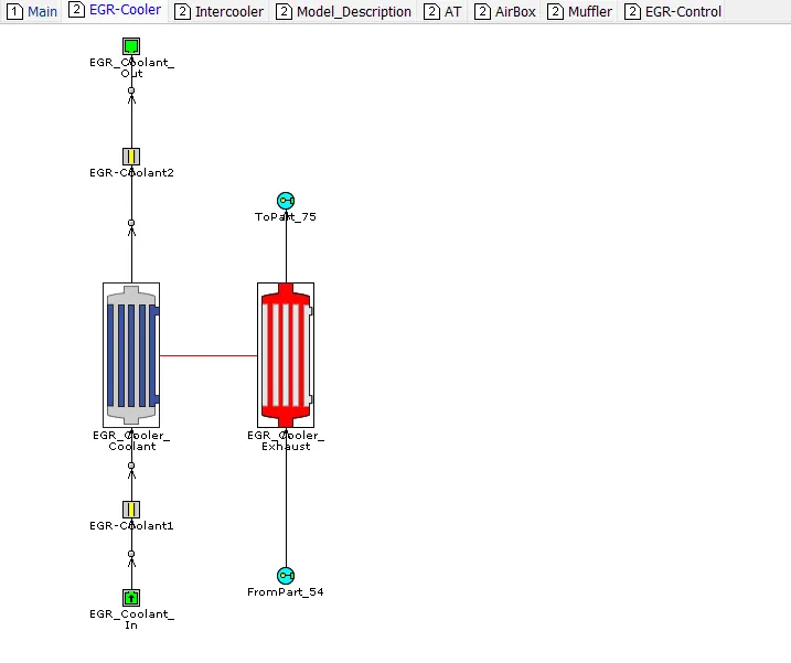
- The EGR cooler is modeled using 'HxMaster' and HxSlave' parts. Coolant side boundary conditions are imposed. The heat exchanger model inputs include geometry along with measured heat transfer and pressure drop performance data. During model pre-processing, the measured data is used to generate non-dimensional correlations for heat transfer that allow the model to accurately predict heat transfer rates at any operating condition.
- The pressure drop data is use to automatically calibrate physical characteristics (friction multiplier, orifice Cd) of the heat exchanger so that the data is well matched.
The Turbocharger and Boost Controller:
- The turbocharger in this model contains a fixed geometry compressor and a variable geometry turbine (VGT). For the VGT, there are 5 different sets of turbine map data entered at each of 5 VGT rack positions. The VGT rack position is determined by a control system to achieve a target boost pressure upstream of the intake manifold.
- The boost pressure is sensed and is then filtered using a Moving Average' part to produce an average pressure signal. The model based controller compares the sensed boost pressure to the target boost pressure and then adjusts the VGT rack position accordingly.
The Exhaust System:
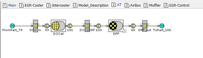
- A full vehicle exhaust system is modeled downstream of the turbine outlet. The geometry of a Diesel Oxidation Catalyst (DOC) is modeled using a 'CatalystBricR part. In this example only the pressure drop across the DOC is of interest, so no chemical reactions are modeled in the DOC. The inlet and outlet of the DOC must be modeled using flow splits because the DOC is effectively a bundle of very small pipes.
Just downstream of the DOC is a Diesel Particulate Filter (DPF) using a 'DieselParticFilter' part. In this example, only the geometry attributes are specified so that proper pressure drop across the filter is modeled, but there is no soot accumulation or regeneration modeled. Similar to the DOC, the inlet and outlet of the DPF must be modeled using flow splits.
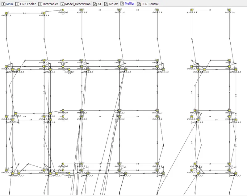
Downstream of the DOC is a muffler. This muffler was modeled using GEM3D, which enables complex muffler geometry to be entered in a CAD tool and automatically discretized into a GT-POWER model. The muffler in this example is a tri-flow type muffler with two baffles. The center chamber between the two baffles is filled with wool, and various internal pipes and baffles include perforation. The .gem file is included in the directory and can be opened in GEM3D to see the muffler. The output of the GEM discretization is stored within an internal subassembly to keep the main project map clean.
EGR-COOLER:
INTERCOOLER:
AT:
AIRBOX:
MUFFLER:
EGR-CONTROL:
CONCLUSION:
- Listed down different TC and located examples from GT Power
- Explored tutorial number 6 and 7
- Plotted operating points on compressor and turbine maps
- Explained in which application Variable Geometry Turbine is beneficial.
- Explored example- Diesel VGT EGR and understand the modeling part.