Week-7 : Converting a detailed engine model to a FRM model
AIM:
- To Explore tutorial number 9 and write a detailed report.
- To Build FRM Model for following configuration using FRM builder approach.
- Bore 102 mm stroke 115 mm CR 17
- No of cylinder 6
- CI engine
- Twin Scroll Turbine
- GT Controller and Run all cases
PROCEDURE:
FRM Model:
- FRMs execute much more rapidly than the typical detailed GT-POWER engine model, and are ideal for integrating with other vehicle systems where an accurate and predictive engine plant model is desired and where computational speed is critical.
- FRMs adapt to changing conditions (e.g. valve timing, spark/injection timing, turbo lag, external temperature, altitude, cooling system conditions, etc.) without the need to apply non-physical correction factors.
- Whether studying changes to ambient conditions, or simulating events that are heavily transient in nature, FRMs will maintain the predictive capabilities of a detailed engine model while allowing for the fast computational speeds that are expected when performing drive cycle analysis and other transient-focused simulations.
Explore tutorial number 9:
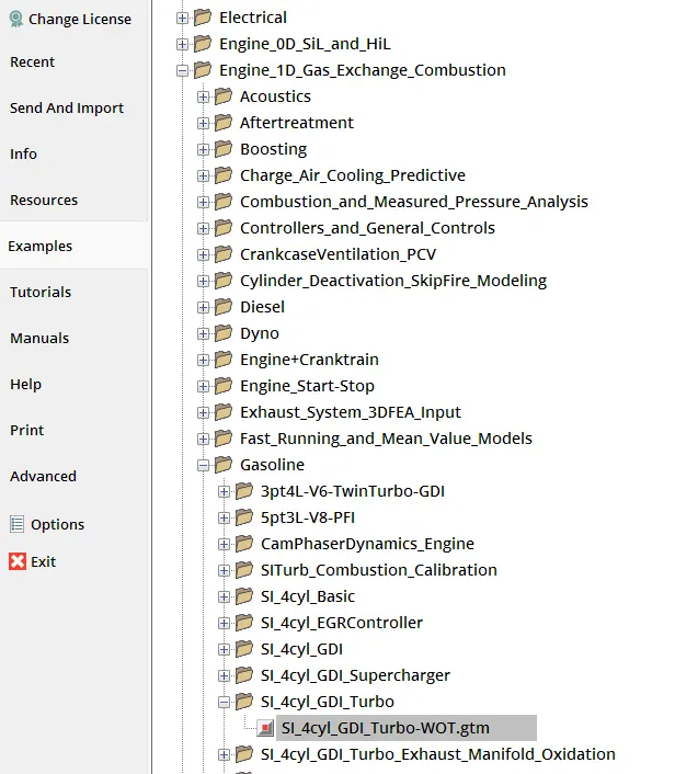
Go to File ->Examples->Engine_1D_Gas_Exchange_Combustion ->Gasoline ->SI_4cyl_GDI_Turbo ->SI_4cyl_GDI_Turbo-WOT.gtm
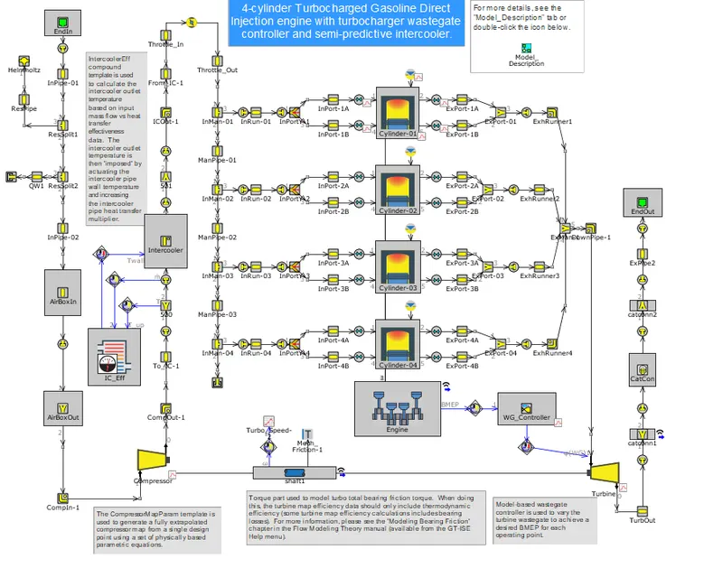
We will convert this detailed model into FRM based on accuracy or speed, in this tutorial the simplification is done based on accuracy so as to compare the engine performance parameters from detailed model as well as FRM and to determine the accuracy.
Exhaust Manifold:
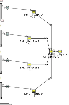
We will simplify the exhaust manifold,so the maximum time step limit of 1 crank angle degree will be removed. If the courant condition allows for a larger time step to increase in size
Exhaust Pipes:
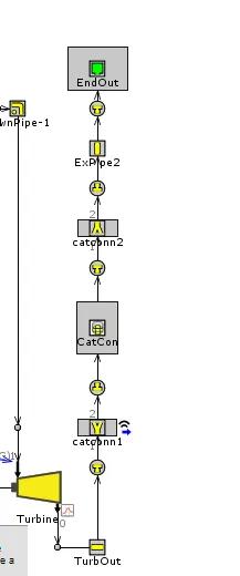
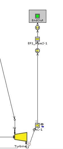
Now the exhaust pipes downstream of the turbine is simplified. There a new object was named as CAC.
The newly created CAC1 part was opened and Thermal tab was selected. GasT reference object was selected. Value selector for Wireless Signal or RLT was selected. Value for Exhaust Pipe dia was chosen to be 40mm.
Intake Manifold:
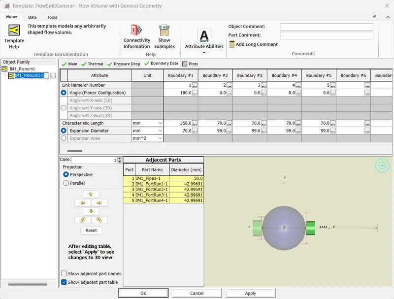
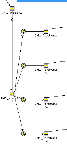
Intake Manifold was selected from FRM convertor and "Simplify for accuracy" option was selected.
Compressor Outlet Pipes:
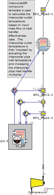
Select boost pipes 1 from the tagged subsystem list click on simplify by accuracy. Since the intercooler core has been replaced with a flowsplit and HeatExchangerConn part. The BP1_CACC1-2 HeatExchangerConn part will be used to assure the intercooler outlet temperature is maintained.
Intake Pipes:
Intake pipes select intake pipes 1 from the tagged subsystem list. Click on simplify for accuracy. Collapse the FRM converter to provide space to work in the model map.
Exhaust Manifold:
The Exhaust Manifold is selected from FRM converter. "Simplify for speed" is selected
For calibration all cases were enabled for calibration. Turbine Massflow Averaged Inlet Temperature is chosen as the parameter.
Cylinder Slaving:
This simplification to the model will utilize the Cylinder Slaving capability. By right clicking on any of the EngCylinder slaving option. For full cylinder slaving to function, each valve must be specified as either an intake or exhaust valve.
Final model will be:
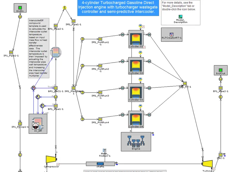
Now we will run the case with the default case values:
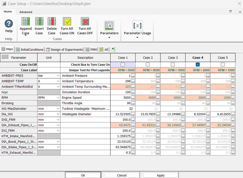
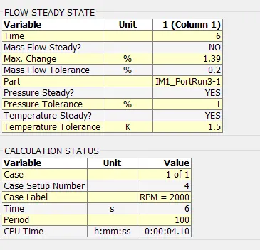
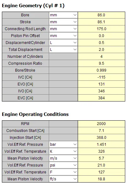
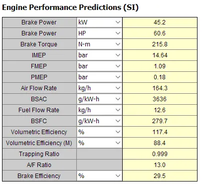
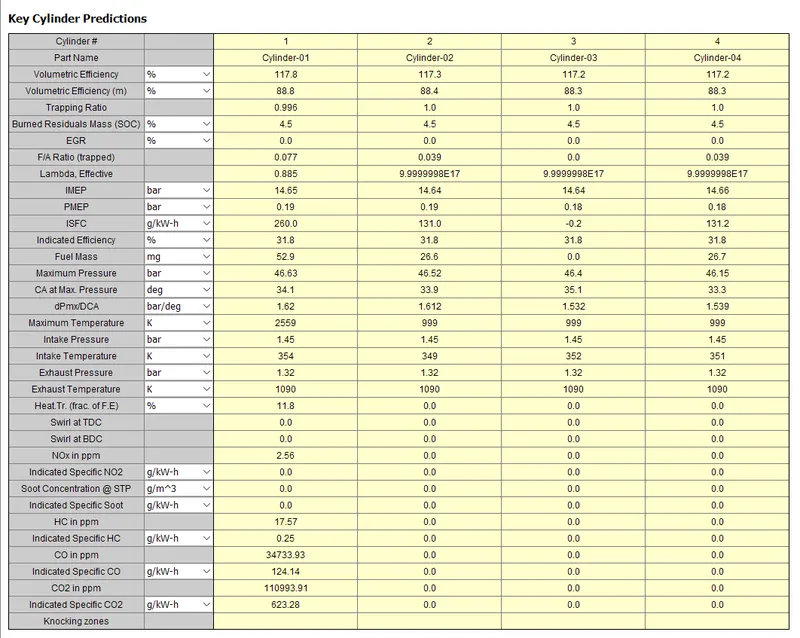
Let us build a FRM for following configuration using FRM builder approach
- Bore 102 mm stroke 115 mm CR 17
- No of cylinder 6
- CI engine
- Twin Scroll Turbine
- GT Controller
We will set the conditions under tools option FRM builder as follow:
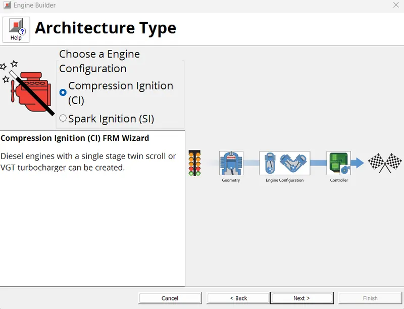
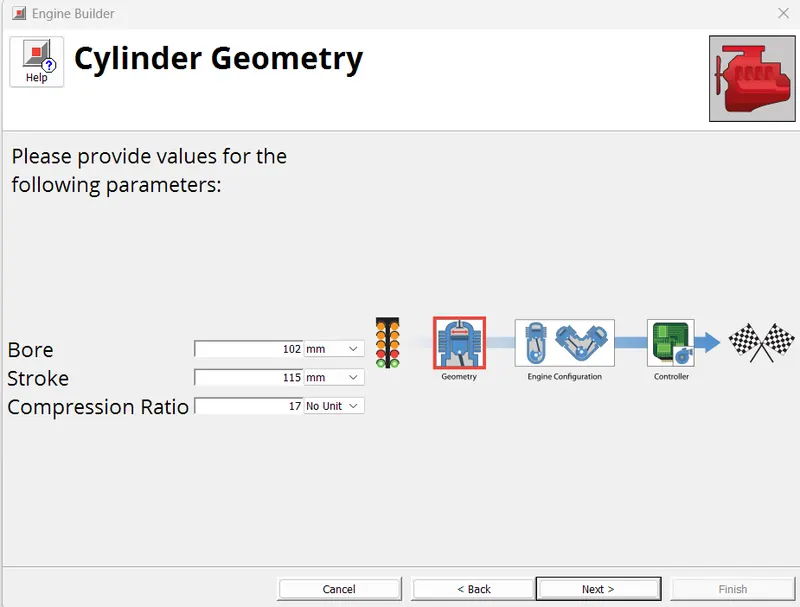
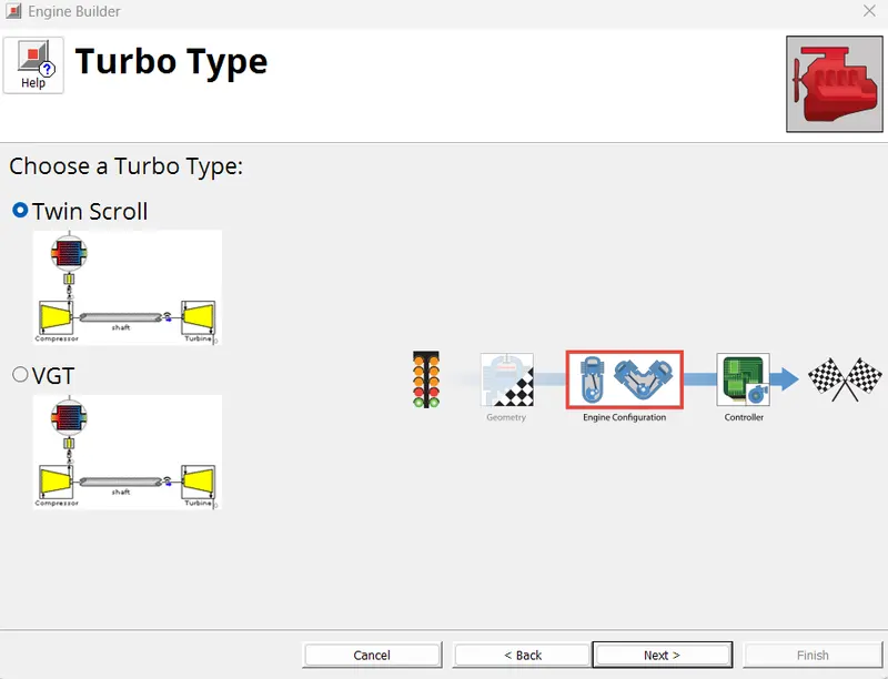
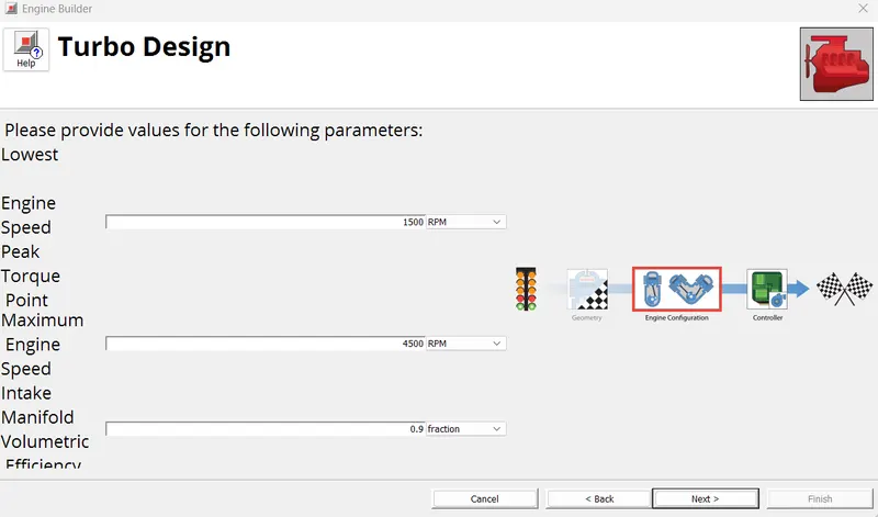
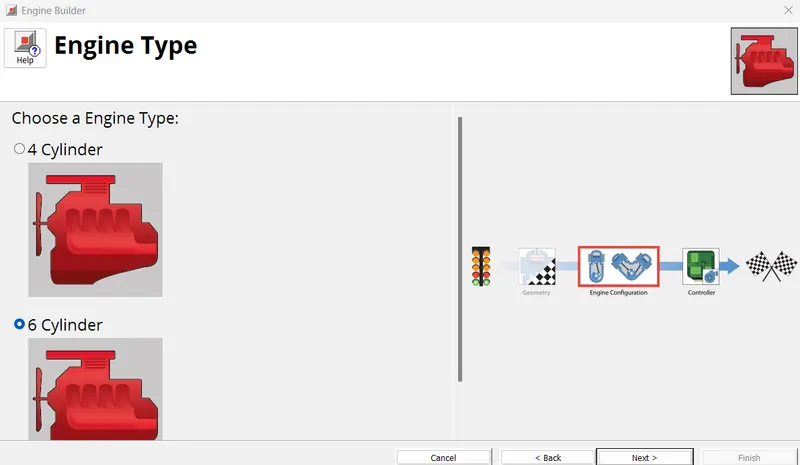
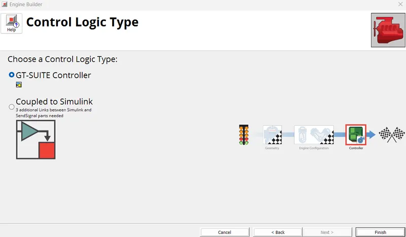
This gives us the below engine model
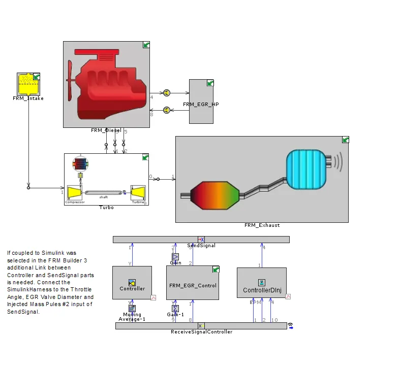
We will run for the one case only:
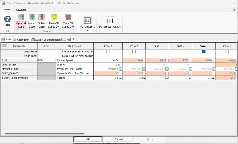
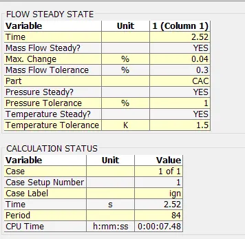
6 cylinder Turbocharged Diesel Engine VS FRM model
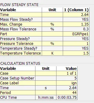
The detailed model took 6 sec for 100 period wheras FRM took 2.64 sec for 44 period. However when comparing the CPU time we see that detailed model took 4 mins and 10 sec while the FRM took 3 mins and 75 secs which is less than the detailed model.FRM is reliable for our simulation.
Now we will compare by running all the cases:
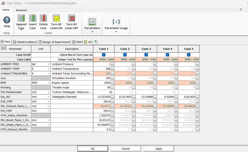
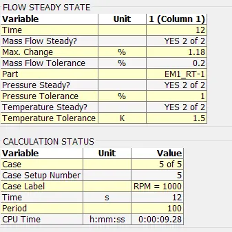
6 cylinder Turbocharged Diesel Engine:
FRM Model:
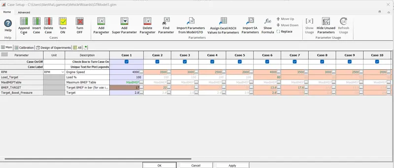
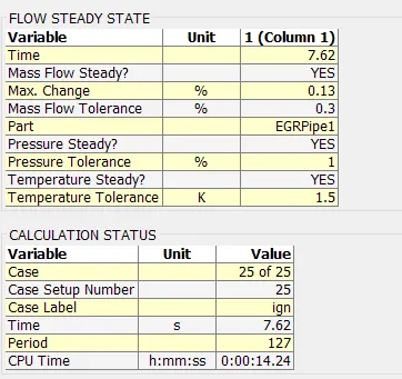
The detailed model took 12 sec for 100 period (5 cases) wheras FRM took 7.62 sec for 127 period (25 cases) . However when comparing the CPU time we see that detailed model took 9 mins and 28 sec while the FRM took 14 mins and 24 secs which is double than the detailed model.
CONCLUSION:
- Explored tutorial number 9 and Given a detailed report.
- Done simulation by FRM Model for given configuration using FRM builder approach.
- We have also compared the time cases for both detailed and FRM model and concluded that FRM model is suitable
- Runned all the cases for FRM model = 25 cases and Detailed Model = 5 cases