Week 3 Challenge : CFD meshing on Turbocharger
Aim:
For the given model of a turbocharger, check for the geometrical errors to make appropriate volumes by creating and assigning the PIDs accordingly. Create surface mesh using the given target length
- Blade stage-1 = 1 mm
- Blade stage-2 = 1 mm
- Impeller = 2 mm
- Shaft rotor = 1 mm
- Turbo casing = 5 mm
- Compressor casing = 5 mm
- Inlet casing cover = 5 mm and Perform volumetric mesh
Procedure:
1. Importing the file:
- To import the given file to ANSA
- In ANSA, Go to File -> select Open
- Select and open the given file with .ansa extension
- The model is opened in ANSA
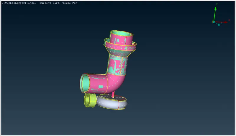
2. Topo clean-up:
- After opening the model we have to check the geometry of the model
- Go to Toolbar -> Checks -> Geometry Checks -> enable the mode to check error and give Execute
- We can find single and triple cons .
- We can find double colours in the model as the unnecessary surface overlaps
- Delete the unnecessary overlapping surface by using Delete->PID region->select the surface to be deleted
- After deleting the overlapping surfaces,we will fill and solve the single cons.
- Using TOPO-> Faces-> New -> COONS
- Certain Surfaces cannot be created by using the New option, so that we will create certain hotpoints that will be projected so that small surfaces can be created
- We can use intersect option to delete the surface which has no separate entity,now that surface can be deleted
- After the single cons are solved ,Now we will focus now on solving for triple cons located at the shaft region
- Since we need to have a single volume which makes meshing easier. Delete the overlapping surfaces to reduce them to double cons
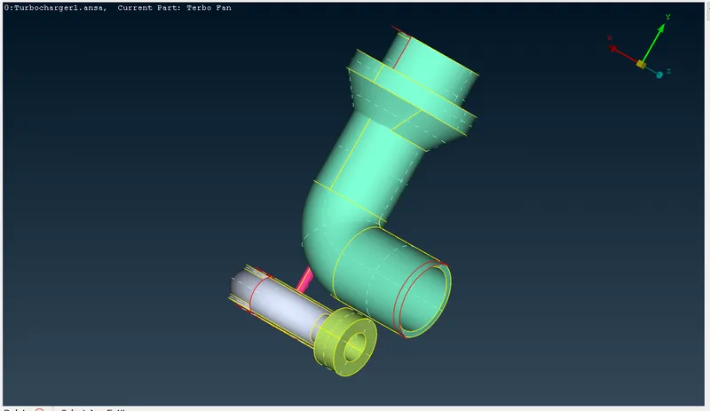
3. Rename PIDs and assigning the surfaces:
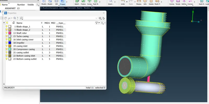
- Go to Properties -> there will default PID .
- In order to create different New PIDs , Right click -> select new -> then select PSHELL -> then select PSHELL -> then give name in the popup box -> then OK .
- You can change the colour by double clicking on the colour box .
- We will rename the PIDs as Compressor casing,Turbo casing,Inlet casing cover,Blade stage 1&2 ,Impeller,Shaft rotor .
- To assign , click on the PID -> right click on it -> then click on apply -> then in the geometry select the cross hatch of the surface you want to assign -> middle click .
- In the similar way we have to apply for all different PID's
- we will delete the empty PID which has no surface on it
4. Surface meshing:
- We need to mesh each component as per the given target length, so that we will mesh the component individually.
- Enter the quality criteria and mesh parameters and length of the mesh accordingly for each component.
- while entering the mesh length, be careful of the change in mesh length between components with different mesh length, when they come in contact they tend to erase the other mesh
- while entering the perimeter and macros we need to give a range ranging from the bigger to smaller mesh length to avoid the mesh to get erased.
- After the mesh is generated, we can create a boundary of the varying mesh length and maintain a constant mesh length on the other side of the boundary.
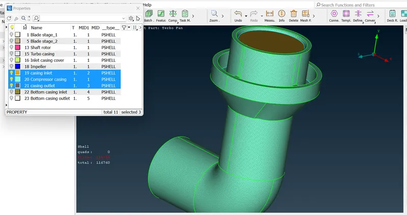
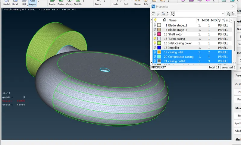
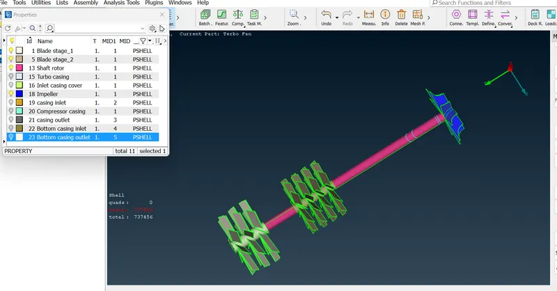
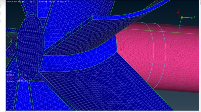
- After surface meshing ,we will find same surface are unmeshed due to variation of target length
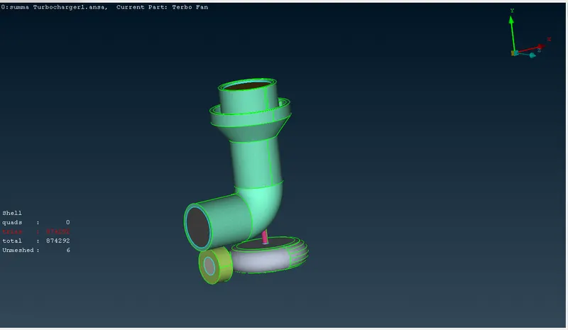
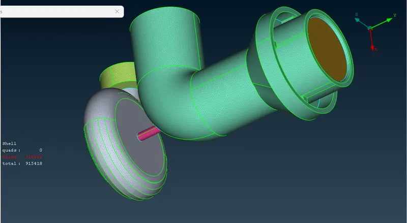
5. Volumetric meshing:
- After the surface meshing is done, we can now achieve volume meshing.
- Under volume meshing, choose define and select whole db in the pop up window.
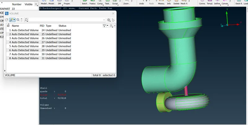
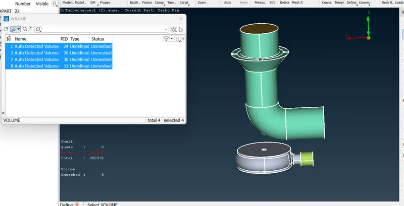
- 3. ANSA identifies various volume present in the geometry, we can delete the unwanted ones and keep the necessary volumes where the fluid can possibly flow in geometry.
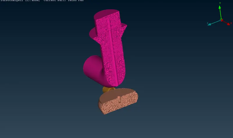
- 4. After the deletig the outer thickness volume and only keeping the fluid volume region, we can remesh each volume using the tetra CFD option under remesh.
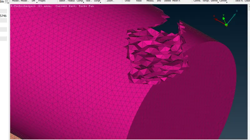
- 5. After each volume is remeshed, the volume mesh can be viewed for each component.
Learning outcome:
As a new learner we learn to Check for geometry errors and delete overlapping regions to improve mesh quality. We will also learn to correct the triple cons and single cons . Creating surface mesh individually and also maintaining mesh length range at the contact region between 2 different mesh lengths and we also learn to Identify and create volumetric mesh only for the fluid region part and tools
Result:
- We have done the geometry clean-up with all the inlets and outlets closed to create a closed volume
- We have renamed the PIDs and asssigned the components to them
- Surface Meshing is also done with different mesh lengths as per the given criteria
- Volumetric mesh created for the fluid volume region along with cut sections to view the 3D mesh
Completed file on google drive
https://drive.google.com/file/d/1FHl0zQ9cOqa1Gi6lIWpv5gBfdrtfM4ia/view?usp=sharing