Week 4-1D Element Creation Challenge
AIM
- To create a Midsurface for the given Model
- To Mesh given component with the size of 5 Units
- To create RBE2, RBE3 links and 1D Elements on the following component with given cross-section and DOF at given locations
GIVEN DATA
a. Rod element:- Translational DOF should be Constrained with RBE2 link
Cross-Section: BOX- Dimension a= 12 mm
dimension b=10 mm
Thickness t= 0.75 mm
b. Beam element:- All DOF should be constrained with RBE3 link
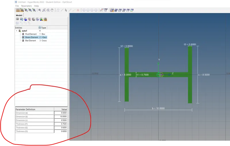
Cross-Section: I Section- Dimension a= 8 mm
Dimension b= 10 mm
Dimension c= 8.5 mm
Thickness t1= 0.75 mm
Thickness t2= .6 mm
Thickness t3= .6 mm
c. Bar element:- Constrain only x and y DOFs With RBE3 link
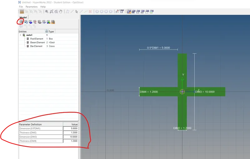
Cross-section: X section- Dimension DIM1= 5 mm
Thickness DIM2= 1.2 mm
Dimension DIM3= 10 mm
Thickness DIM4= 1.2mm
d. & e. Apply the mass of magnitude 10 with the RBE2 link
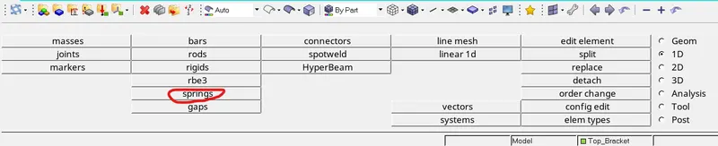
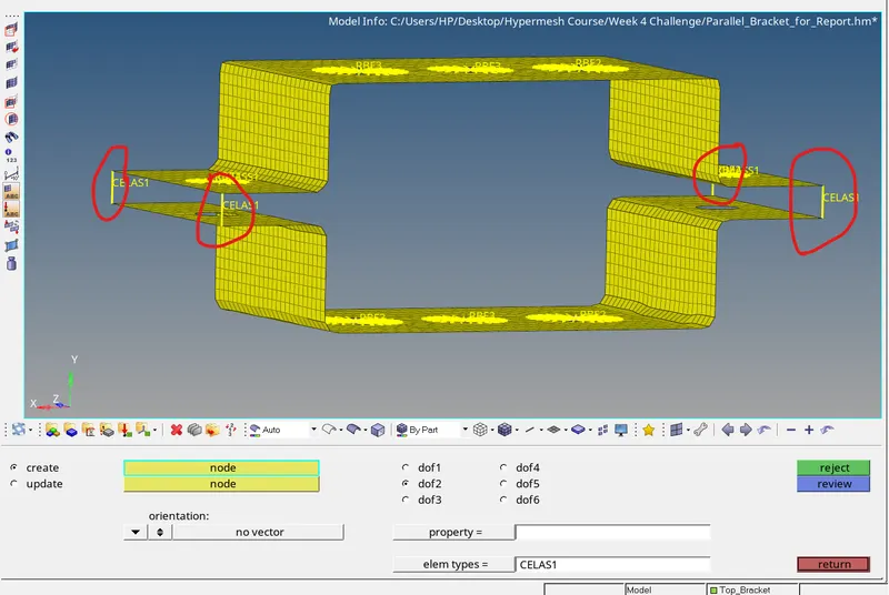
f. Join the two components with Spring elements
PROCEDURE
PART 1 - Creation of Midsurface
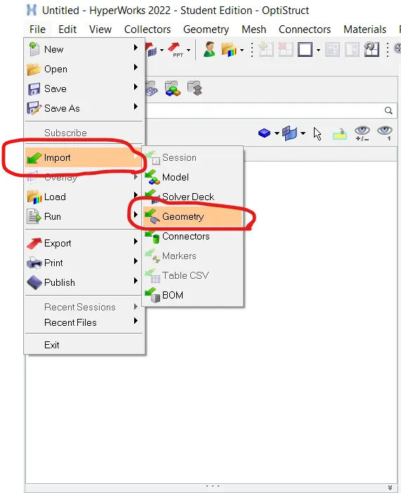
1. Using Import -> Geometry Command, given Iges file Imported. Below pictures shows how geometry is imported inside hypermesh workspace.
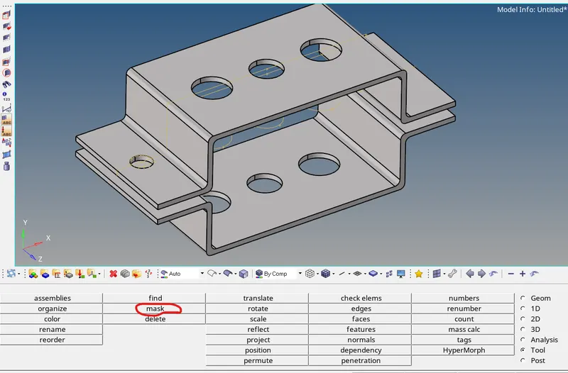
2. Unwanted lines kept hidden using mask command. Below pictures demonstrates masking process.

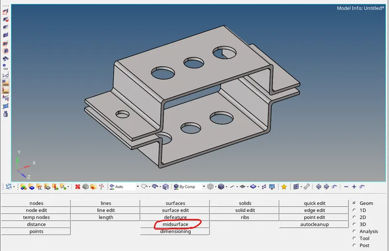
3. Next step is to create a midsurface for Top and Bottom Bracket. Below picture shows Midsurface tab present inside geometry panel.
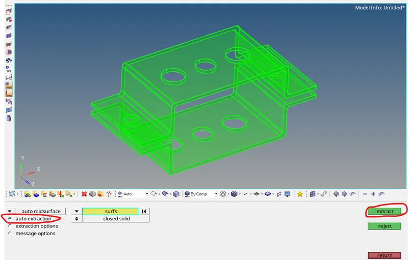
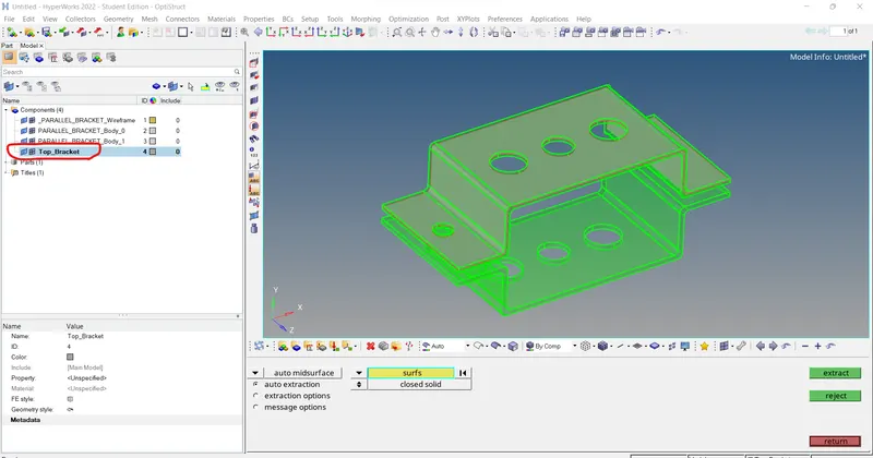
4. Auto Extraction command is used to create midsurface. After selecting top bracket and clicking on extract option midsurface is created. It is renamed as Top_Bracket
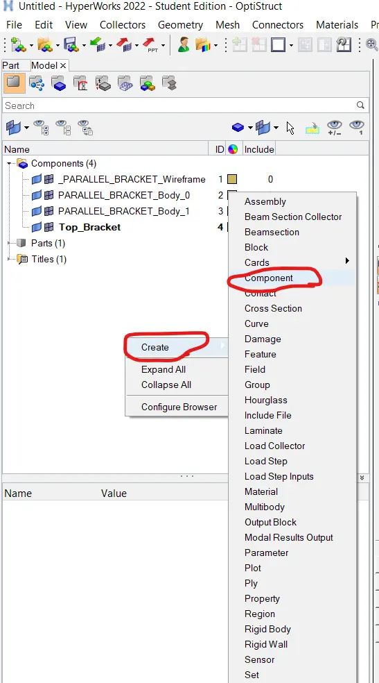
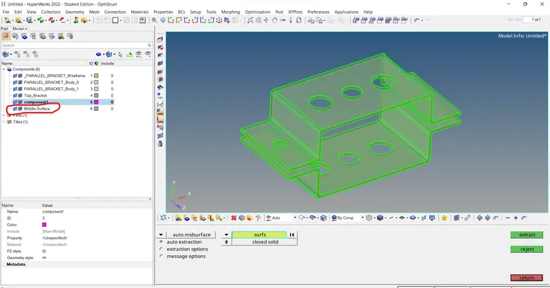
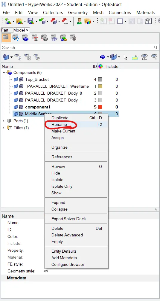
5. To Create mid surface for bottom bracket new component is created by right clicking in feature tree graphic area and performing Create->Component operation. By performing same steps midsurface for bottom bracket is created and rename as bottom_bracket. All the solid models have deleted.
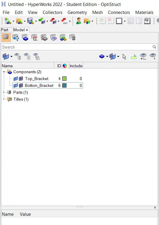
PART 2 - Meshing of given component with the unit size of 5 unit
1. To make proper mesh at area around hole, washer split command is used. It splits the surface with given offset value. Below pictures shows how washer split is performed.
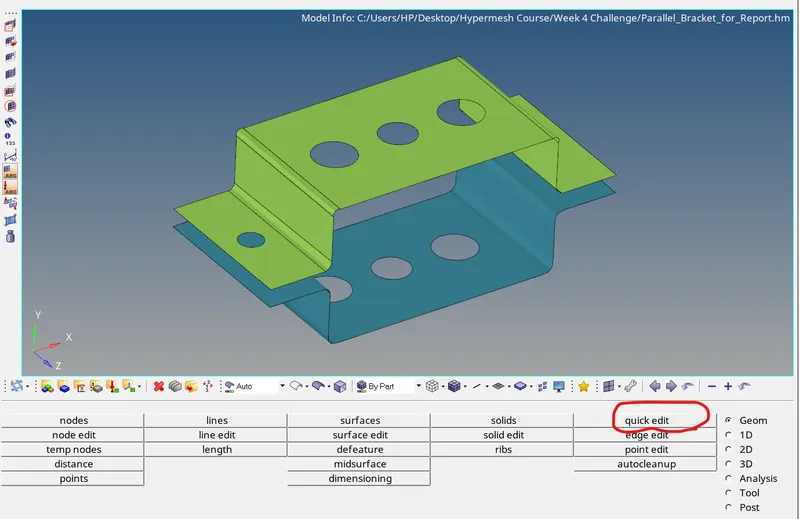
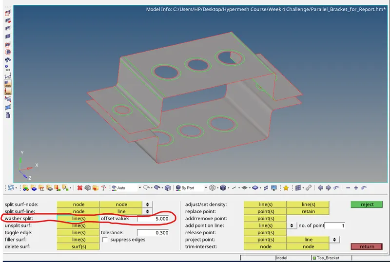
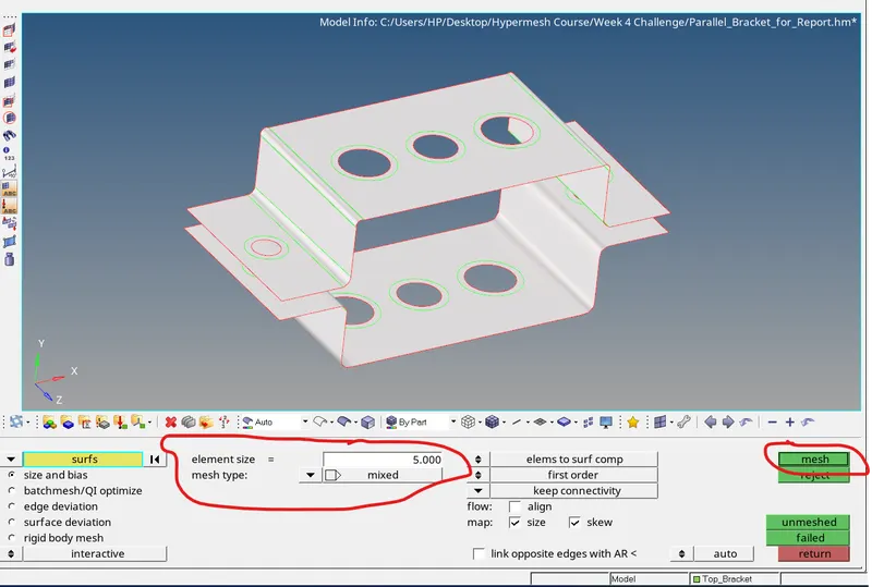
2. To create 2D mesh automesh command is used present inside 2D mesh panel. Element size of 5 and mixed mesh type options are slected. By clicking on mesh option reqiuired mesh is created.
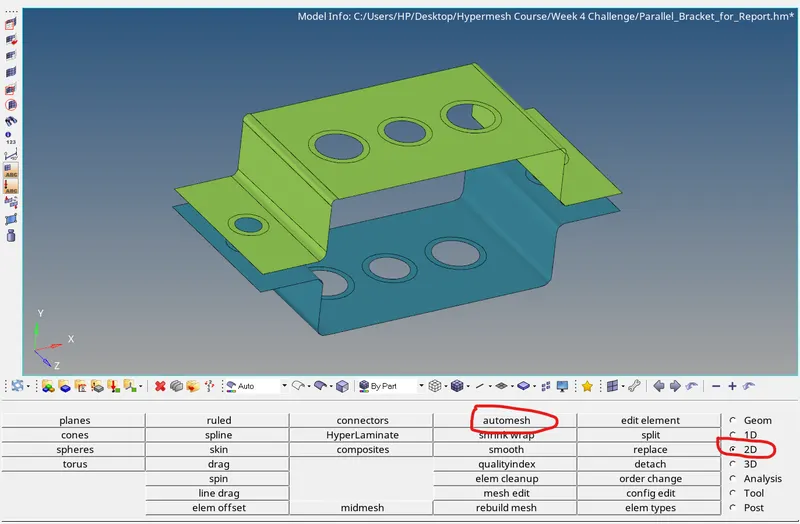
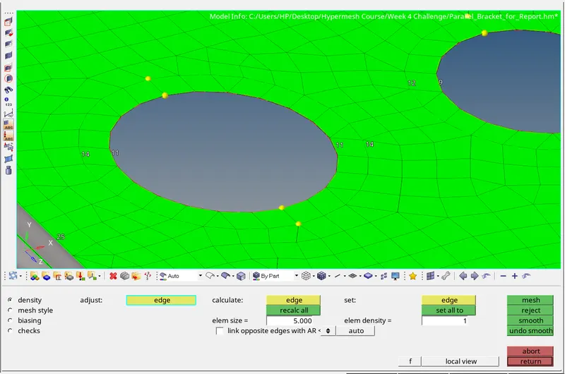
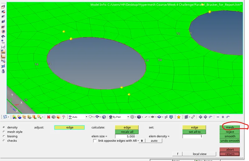
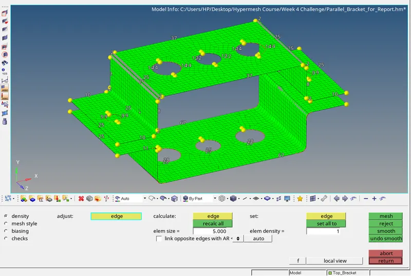
3. Generated mesh is uneven near hole region. To make it even number of nodes, inside hole and outside hole are made equal which in case are 14 nodes. By left clicking on number 11, nodes have been increased to 14 which in turns to be equal nodes. In this way 2D mesh is created. Below pictures shows necessary steps which have been performed to create required mesh on the given component.
PART 3 - Creation of 1D Elements on the following component with given cross-section and DOF at given locations
A) Creation of links at given positions
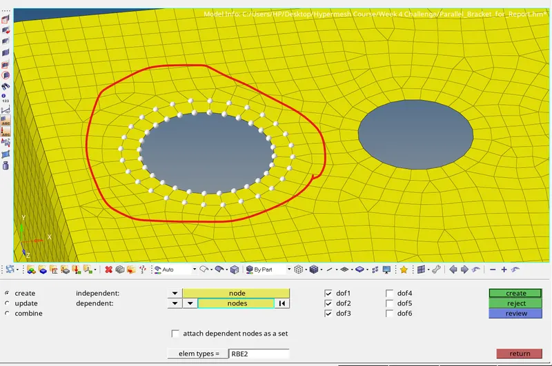
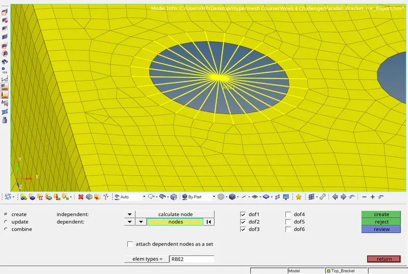
1. As per given Specifications for position a, RBE2 link is created by constraining x,y and z translational DOF. rigids command is used to create RBE2 link.
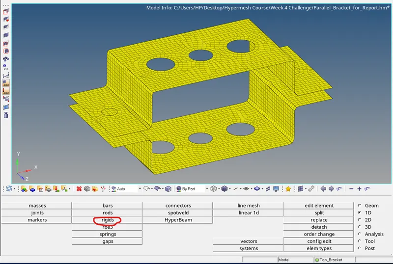
2. Below picture shows that x translation (DOF1), y translation (DOF2) and z translation (DOF3) are constrained.
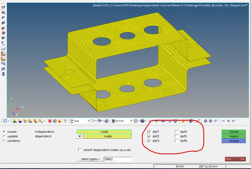
3. To create nodes, calculate node option is selected.

4. To create multiple nodes at one time, multiple nodes option is selected from selection list.
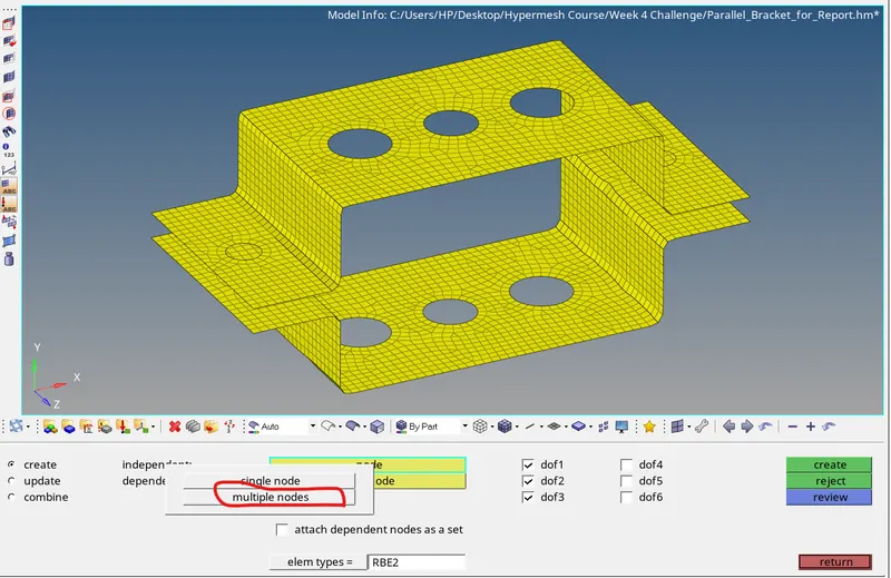
5. To save time, by path option is selected for creation of nodes. Software automatically detects the path and creates nodes between start node and End Node.
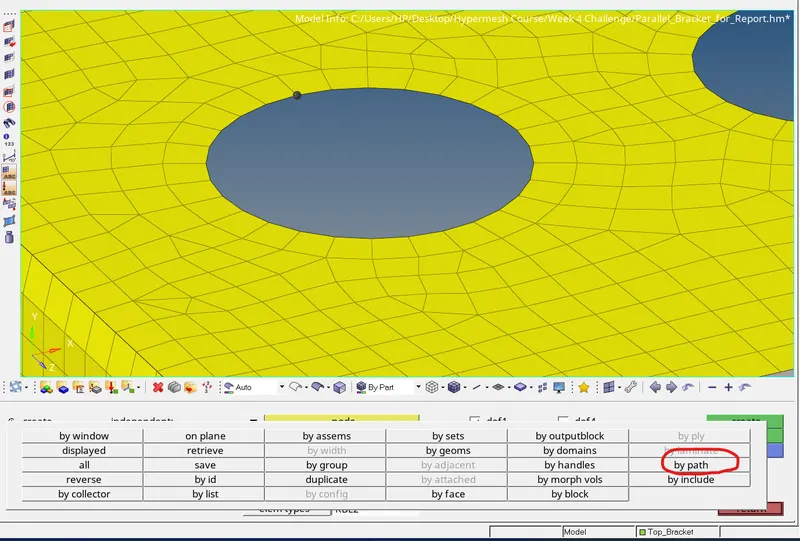
6. Below picture shows representation of RBE2 Element at position a.
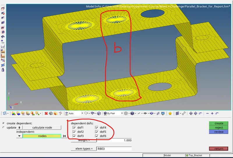
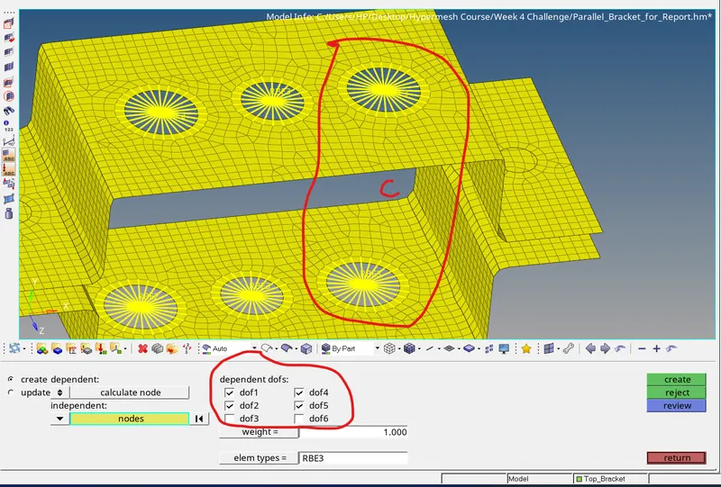
7. In this way necessary links are created at position b and c. Below picture shows RBE3 link at position b with all DOF constrained and at position c with x, y DOF constrained.
8. RBE2 Link is created at position d and e with mass of 10. Below image demonstrates creation of link and mass at position d and e.
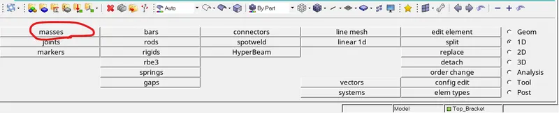
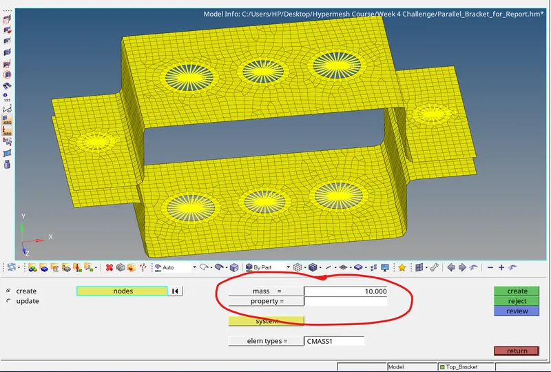
9. Two elements are joined together with Spring Elements. Below Picture shows demonstration of Spring element.
B) Creation of Material
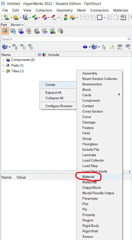
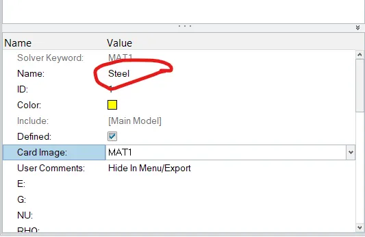
1. By right clicking inside feature tree area follow Create -> Material. For this Model steel Material is assigned with card image MAT1
C) Creation of Cross Section for Elements
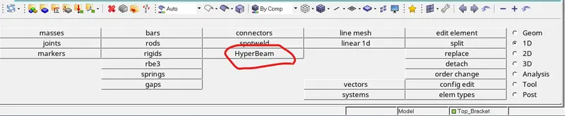
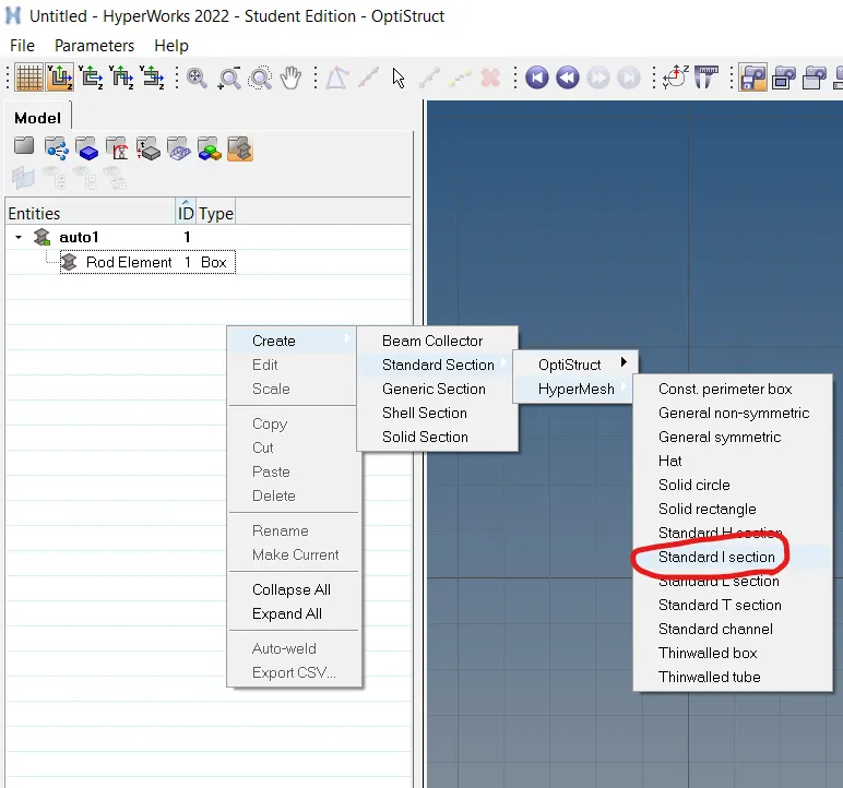
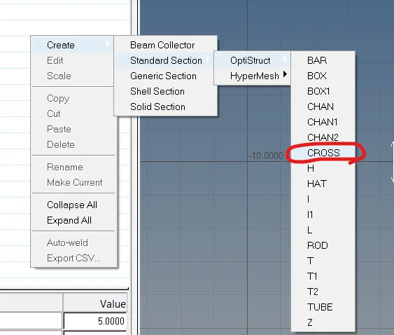
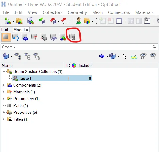
1. To create given cross section Hyperbeam tab is opened which is present inside 1D Panel. Required cross sections are present inside Standard Section -> Standard section library -> Standard section type. By following given dimensions Rod, Beam and Cross sections are created.

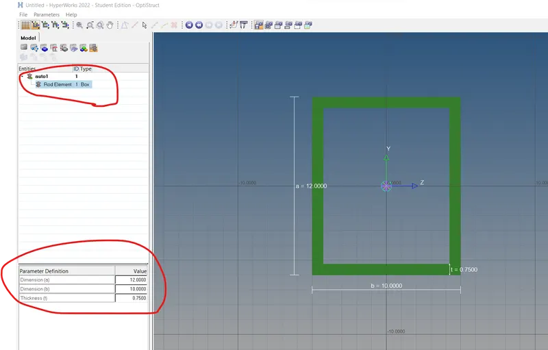
2. In order to Edit cross section following option can be used as shown in below figure.
D) Creation of Properties
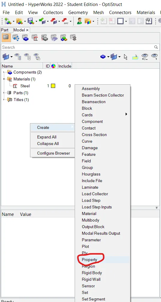
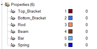
1. By right clicking inside feature tree area follow Create -> Property. For Top and Bottom Bracket PSHELL Card image is assigned with steel Material. For Rod, Beam, Bar and Spring PROD, PBEAM, PBAR and PBUSH Card Image is assigned respectively. Also for Rod, Beam and bar cross sections ( Box, I-Section and X-Section respectively) which has been created in hyperbeam is assigned.
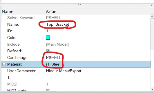
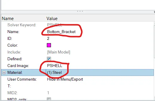
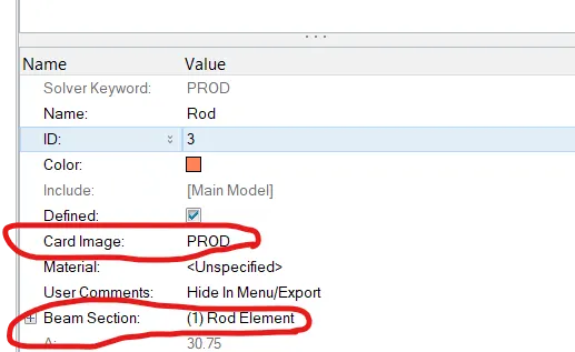
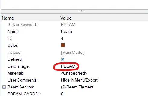
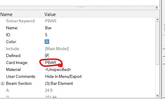
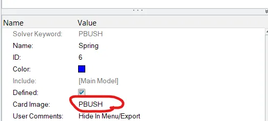
2. All the properties are named as per given data.
E) Creation of 1D Elements at given Positions
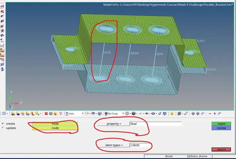
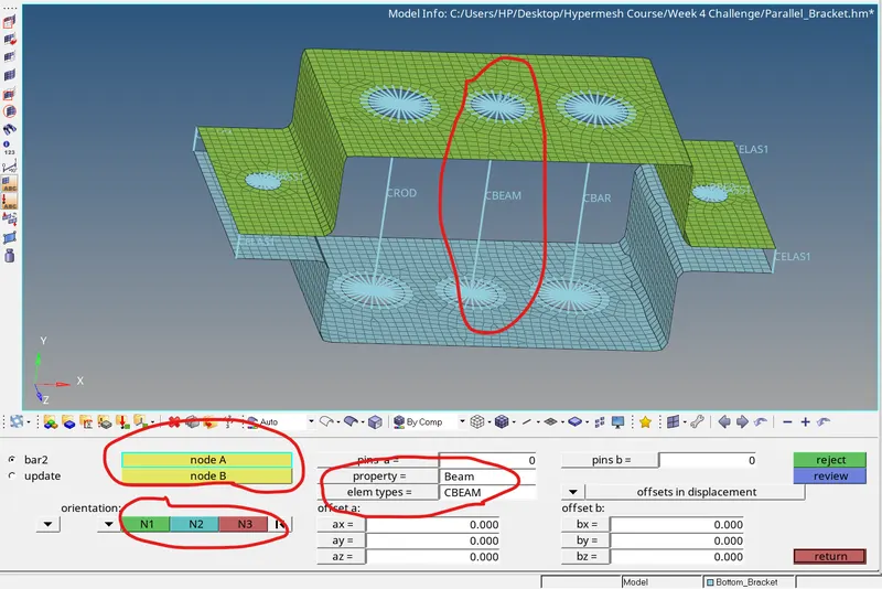
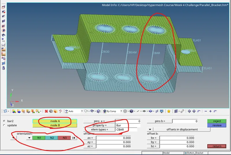
1. To assign created elements at given locations, following steps have been performed as highlighted in below attached images. Node to node selection is made by selecting center points of two holes. As per each specified element, Element property and element type is assigned. For e.g. Rod Element; Property is Rod and Element type is CROD. In this way Beam and Bar 1D elements are Created.

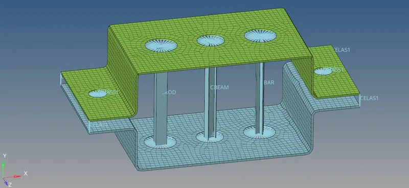
F) Representation of Final Model
In this way all the links and Elements are created. Below image shows final model with all the links and elements.
CONCLUSION
- Creation of RBE2 and RBE3 Links has been Understood.
- Creation of different Cross Sections using Hyperbeam has been Understood.
- Creation of Material, Properties and different 1D Elements has been Understood.