Fender Design Challenge
AIM - Design of front fender of a car
OBJECTIVES
- To create mounting for the Drip area
- To create mounting for A-pillar
- To create mounting for Sill
- To create mountings for Bumper
- To create mountings for Baffles
THEORY
Front Fender

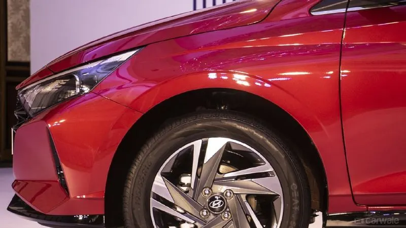
- Fender is the American English term for the part of an automobile, motorcycle, or other vehicle body that frames a wheel well (the fender underside). Its primary purpose is to prevent sand, mud, rocks, liquids, and other roads spray from being thrown into the air by the rotating tire. Fenders are typically rigid and can be damaged by contact with the road surface.
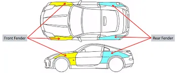
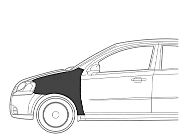
- When a vehicle is moving, the tire picks up stones and others and hurls them in all directions. Fenders are basically present to prevent any injuries to pedestrians and contain the motion of these particles.
Front Fender Types
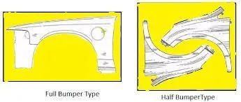
- The front fender has two types which are full fender type and half fender type.
- Full fender is first invented and used fender type. It uses more material while manufacturing.
- Half fender type has been used by all the automobiles present now. It uses very little material as compared with the full fender type. Hence it is lightweight in construction. By reducing the weight, the inertia required to overcome the car will be reduced. Hence, eventually, engine performance will increase.
- While manufacturing the fender, it is possible to make two half fenders with the same material, which is used to make a full fender. The below image shows the material sheet having full fender as well as a half fender.
FENDER MOUNTINGS
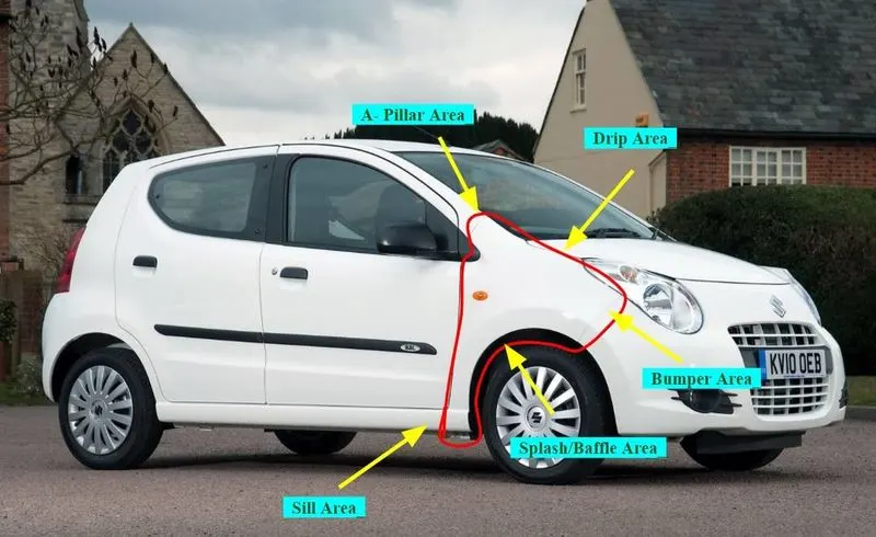
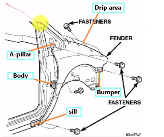
- The fender has five mountings which are drip, A-pillar, sill, bumper, and baffle. The below image shows the location of the mountings.
Drip Mounting
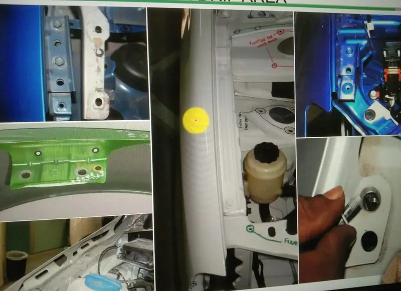
- It's an important and critical mounting in fender design.
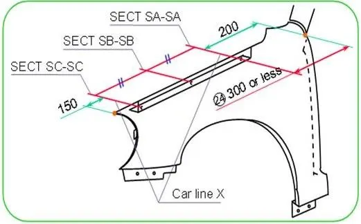
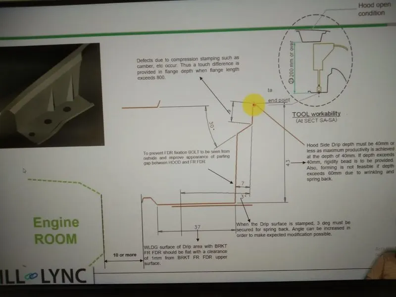
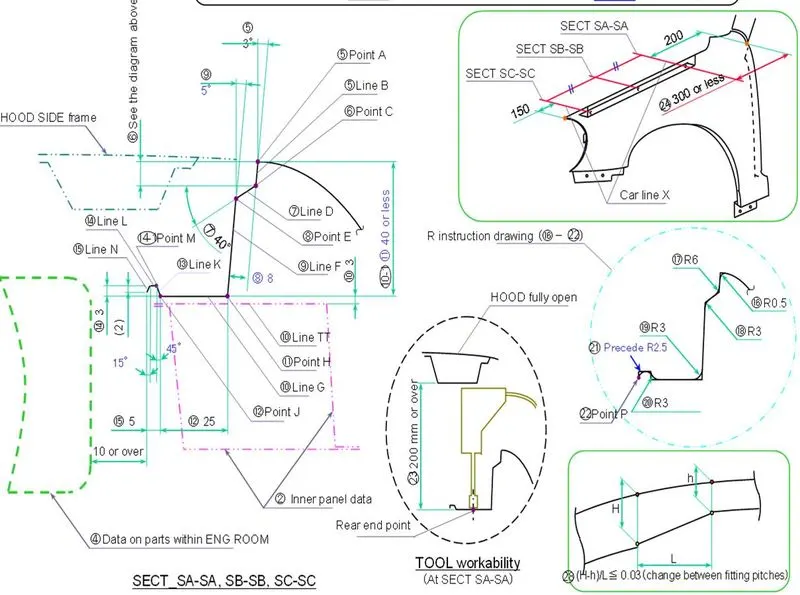
- For placing the headlamp we have to leave a minimum of 150 mm from the front.
- While designing the drip mounting we have to leave a 200-300 mm distance for the cowl top.
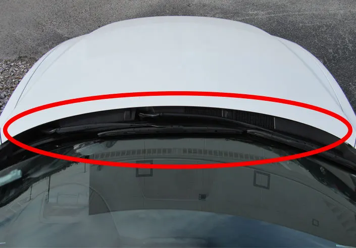
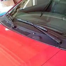
- A cowl is a panel that covers the gap between your car's hood and windshield.
- It supports both the windshield and the dashboard while also protecting the area between the windshield and the hood. It does this by making sure no unwanted elements get into the windshield wiper system or the cabin filter area.
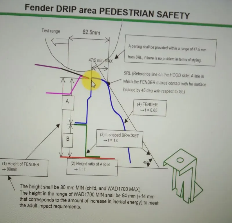
- Rules shown image have to be followed while designing the drip area
A-Pillar Mounting
- The forward-most roof pillar, forming the uprights that support the windscreen. The pillars are named alphabetically by order of placement from front to back of the car.
- The fender has the mounting at the bottom of the A-pillar.

Sill Mounting
- Sill Mounting is present at the rear bottom of the fender where the BIW bottom portion is present.
- The below Image shows the sill mounting.
Bumper Mounting
- The bumper is the frontmost part of the car.
- Bumper mounting is present near the front of the fender.

Manufacturing Process used to make fender
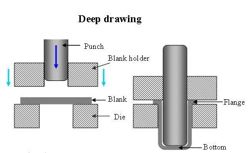
- Majorly all sheet metal components are designed by using a deep drawing process. The below content explains about deep drawing process.
- The illustration depicts the deep drawing technique. A punch, die, and binder is stiff tools.
After inserting the metal sheet blank, the plate holder shuts in deep drawing. - The sheet is then clamped between the die and binder. This procedure slows the flow of the sheet as it is pulled,
preventing wrinkles from accumulating under the binder. The punch creates the sheet in the die by stretching it over the die radius.
As a result, the amount of punch power required for formation is gradually increased up to the punch's lower dead center.
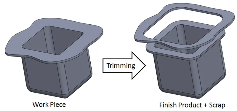
- Trimming is the removal of excess metal from a stamped part to allow the part to reach the finished stage or to prepare it for subsequent operations.
- The below image shows how trimming works.
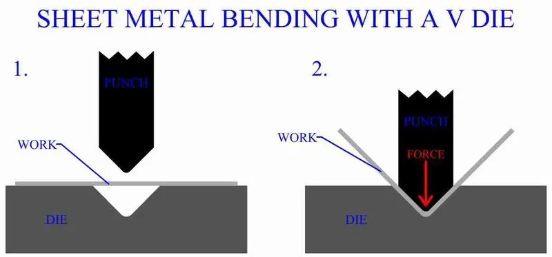
- Bending is a forming operation in which sheet metal is subjected to bending stress thereby a flat straight sheet is made into a curved sheet. The sheet gets plastically deformed without a change in thickness. Die and punch are used for bending.
- The below image shows how bending works

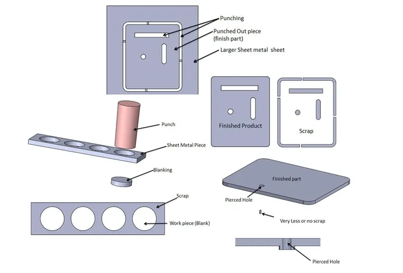
- Piercing is a shearing process in which raw metal is pierced with a machining tool, resulting in the creation of circular or other shaped holes.
- The below image explains how piercing works.

- Below Youtube video below explains how sheet metal components of cars are manufactured
- Right Click Here to open and view the video in the new tab
MAIN CONTENT
- We are provided with a class A surface of a front fender by a styling team.
- The below image shows the given class-A surface.
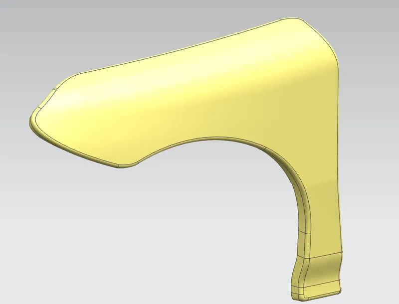
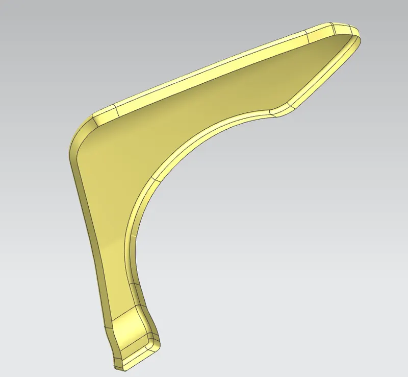
- Drip, A-pillar, sill, and bumper mounting have been created at the required locations of the fender.
Software Used
- Siemens NX 11
Following rules and data have been followed while creating mountings:
- The thickness of the fender should be 0.75 mm
- All the fillets should have a radius of at least 3.75 mm
- All the embosses should have a draft of at least 7 degrees
- There should not be any sharp edges present
Common Commands used for designing mountings
- Offset Surface - This command is used to offset the surface to the required distance from the original surface.
- Trim Sheet - Input for this command is the face of the surface and any curve lying on that face. Using this command unwanted portion of the surface can be removed.
- Sew - It is a joining operation performed to knit or join two or more than two surfaces together to create a single surface.
- Projected Curve - 2D Sketch can be projected onto any flat or irregular face of the surface or body.
- Edge Blend - Fillet can be applied to the edges. Edge is chosen where two surface forms the edge.
- Emboss - With the help of this command any curve can be extruded with some draft.
- Thicken - Used to give thickness to any surface for converting it into a solid body.
- Datum Plane - Reference plane which is created on any solid body, surface body, or with reference of origin.
- Extend Sheet - It is used to extend the surface to the required distance by selecting the boundaries of the surface.
- Offset Curve in the face - It is used to offset the boundaries of that surface.
- Offset - This command is a part of the sketch workbench where entities are offset to the required distance.
Design Of Drip Mounting
- We are provided with a master section for the drip area as it is a critical part of the design considering clearances with the engine compartment.
- The below image shows the given master section for the drip mounting
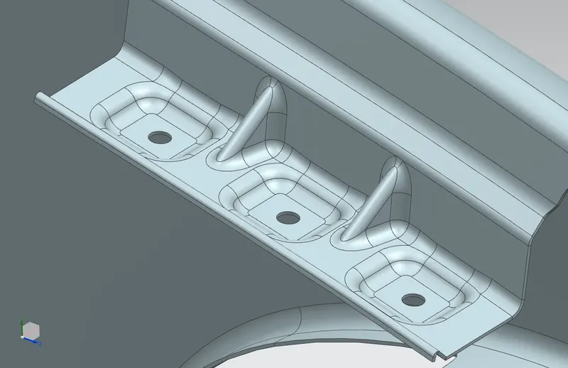
- The below image shows the drip mounting design done using NX 11 software by following all design rules and the Master section.
- Strength is given to the drip mountings with the help of ribs as it is acting as a cantilever beam. Dart feature is used while creating these ribs.
Design Of A-Pillar Mounting
- Provision of a 5 mm hole is provided to all the fasteners being used for the mountings.
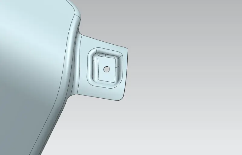
Design Of Sill Mounting
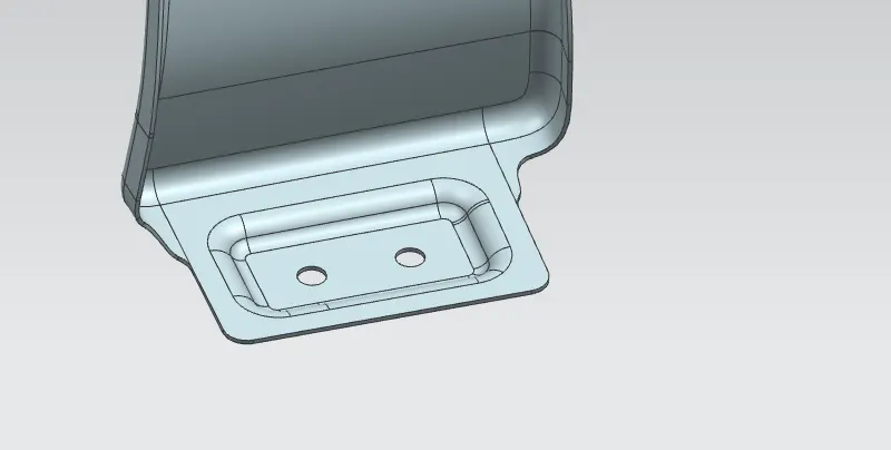
Design Of Bumper Mounting
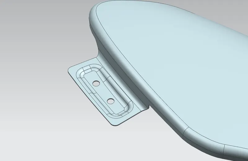
Design of Baffle Mounting
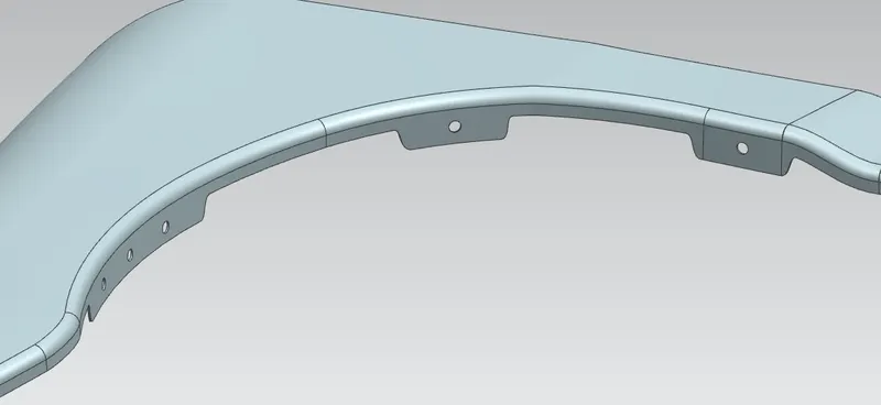
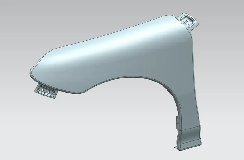
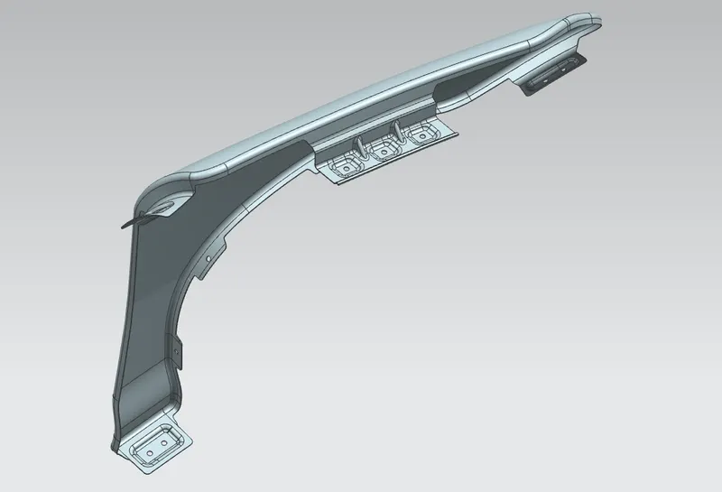
Final Model of Front Fender With all Mountings
CONCLUSION
- All the mountings for the front fender have been successfully designed by following the given Master section and design rules.