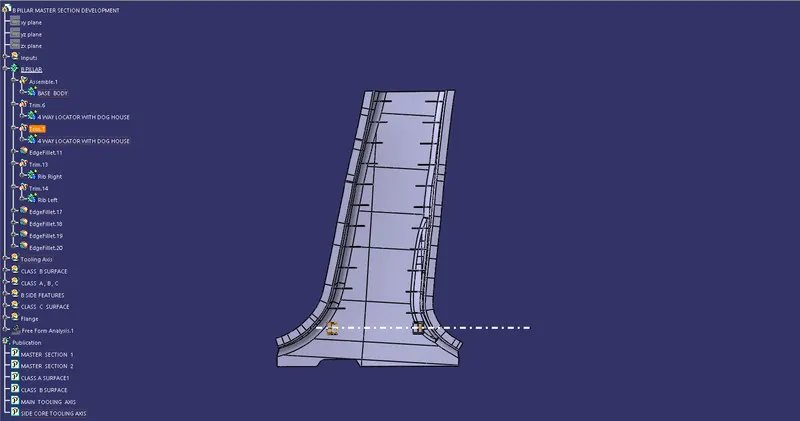
Week 9 - Project - Master Section Development
AIM - To design a B pillar of an automobile.
OBJECTIVES -
- To create the main tooling axis and perform a draft analysis on the class A surface of the B pillar.
- To create class B and class C surfaces.
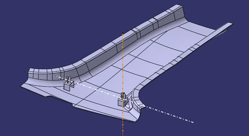
- To create dog house and locator using Master section.
- To perform a draft analysis on the final component.
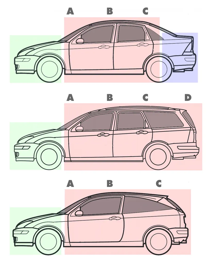
THEORY - Pillars are the vertical support of a car window area designated respectively as the A, B, C, or (in larger cars) D-pillar, moving from front to rear, in profile view.
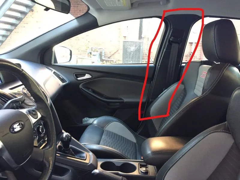
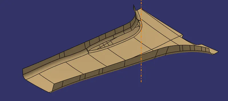
Pillars are of type interior as well as exterior. Interior pillars are made up of plastic which is generally used for aesthetics. Exterior pillars are sheet metal parts that give support to the window area. In this project, we are designing an interior B pillar. The below image shows the interior B pillar.
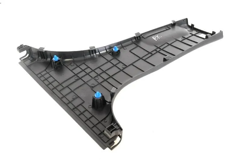
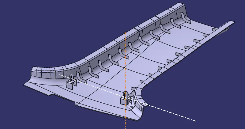
The below image shows the other side of the interior B pillar which has some locators, screw bosses, Ribs, and snap fits. These are called B features used for attaching with the exterior B pillar.
MAIN CONTENT -
MAIN TOOLING AXIS CREATION
- Core and Cavity are opened and closed in the direction of the Main tooling axis.
- The main tooling axis should be in such a way that it should clear the draft analysis.
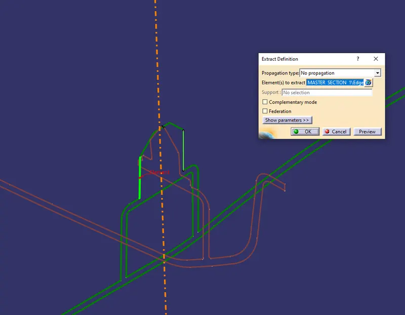
Using Master section 1 two sidelines are extracted.
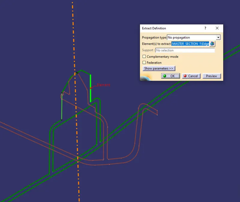
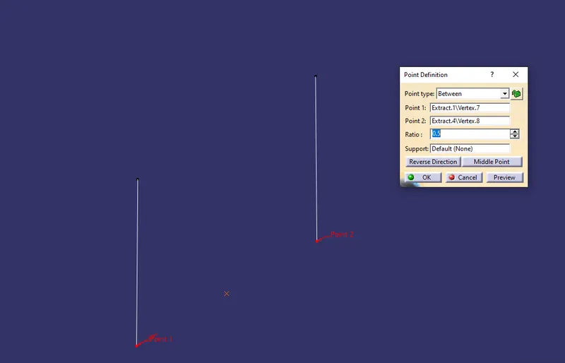
Using these two lines point is created in the middle of these lines.
Using Bisecting method tooling axis 1 has been created.
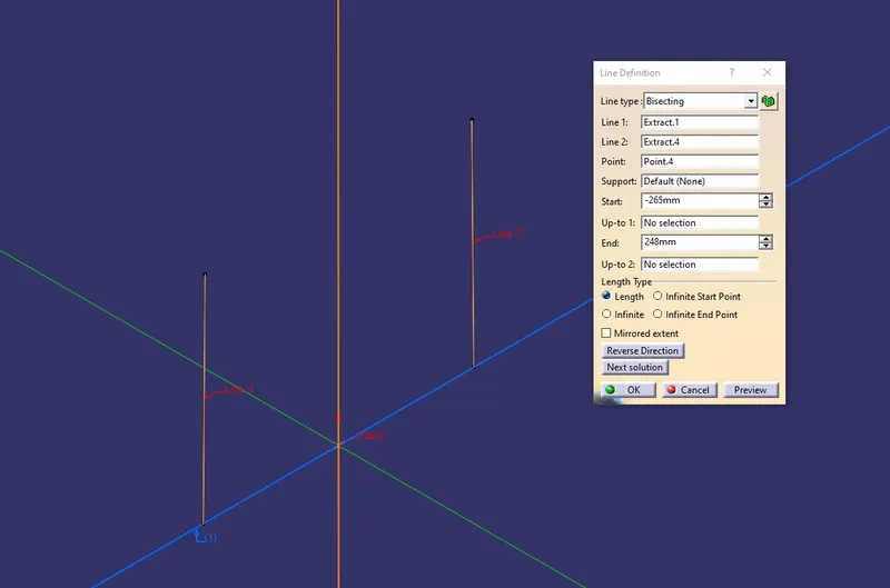

Using sketching method two lines are created by taking reference of master section 2 and then we used bisecting method to make the tooling axis 2.
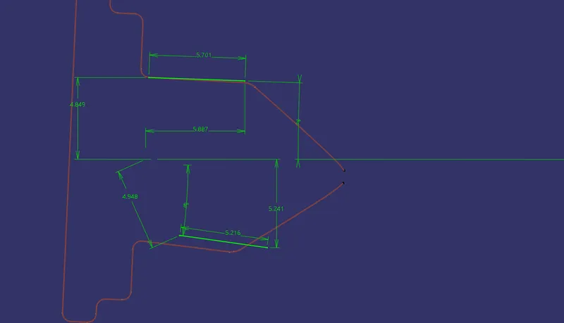
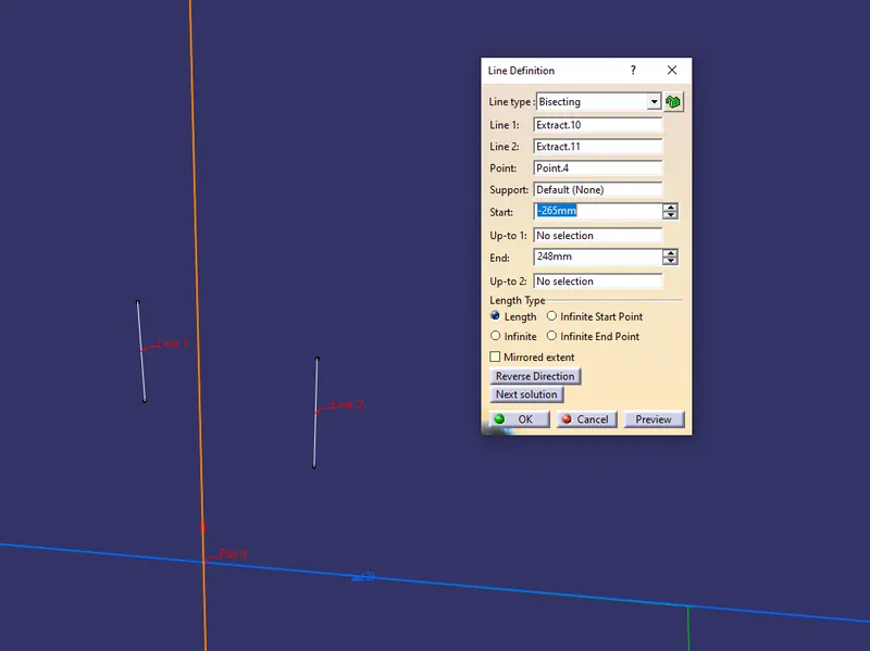
Using bisecting method Main tooling axis has been created by taking tooling axis 1 and 2.
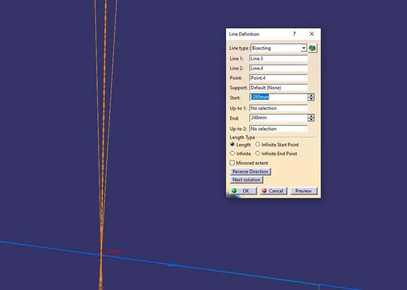
DRAFT ANALYSIS OF CLASS A SURFACE
- Using insert command draft analysis tool has opened.
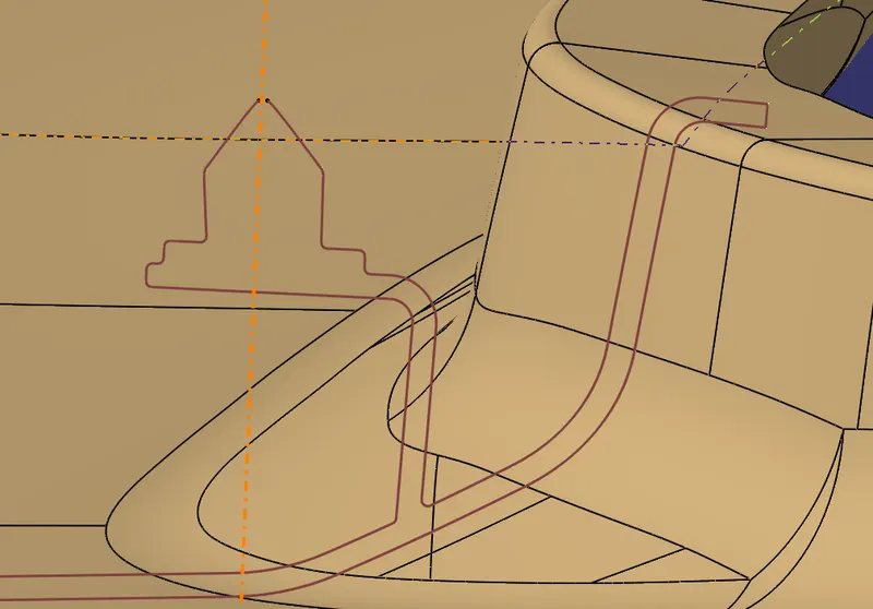
- Note - Flanges are added to the class A surface using the master section profile.
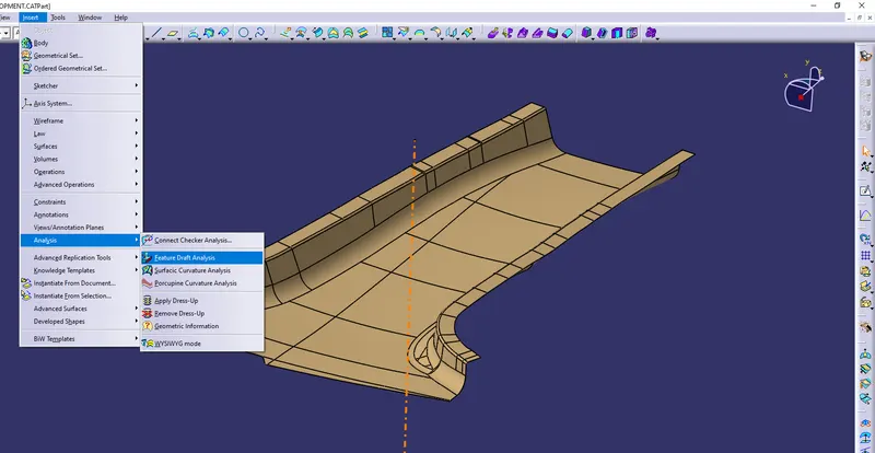
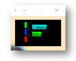
- By clicking on feature draft analysis two pallets opened. One pallet has necessary draft analysis commands and other one is a color range which shows the draft values range in form of color.
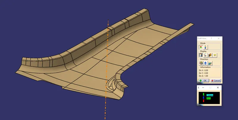
- Inside the draft analysis command window, we have selected the compass option to create a compass.
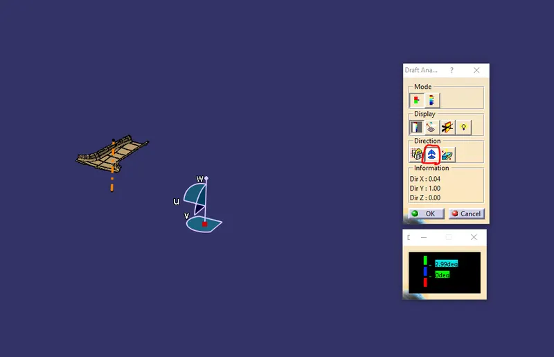
- We have to drag the compass onto the component and align it with the side core tooling axis and lock using the lock command.
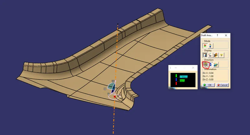
- Now by dragging the mouse pointer anywhere on the component and clicking on it will show us the required draft analysis.
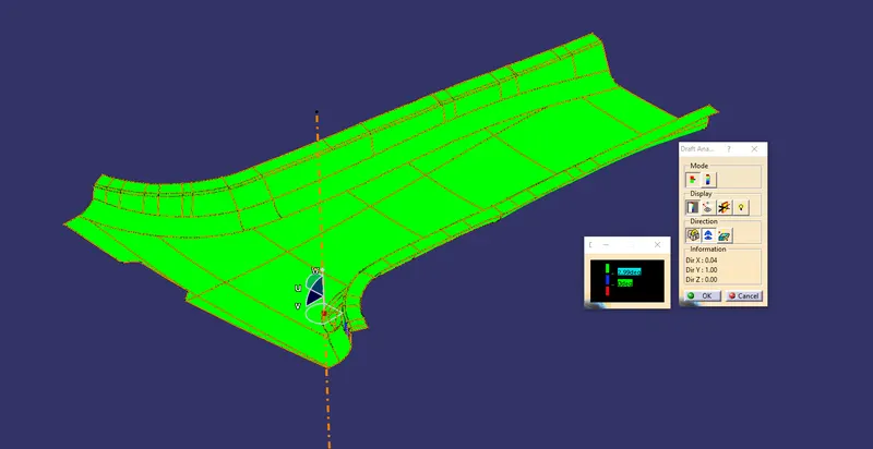
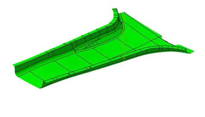
- As per the color scale, the minimum draft angle for all faces should be 2.9 degrees or above that. Inside the color scale, green shows a draft angle of 2.9 or above 2.9 degrees. Blue shows between 0 and 2.9 degrees. And red shows a negative draft angle. As per the above figure, some faces are green and some are blue hence our surface has cleared the draft analysis.
- Below Images shows almost all the faces are having a minimum draft angle of 3 degrees except some faces.
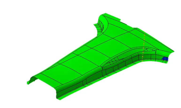
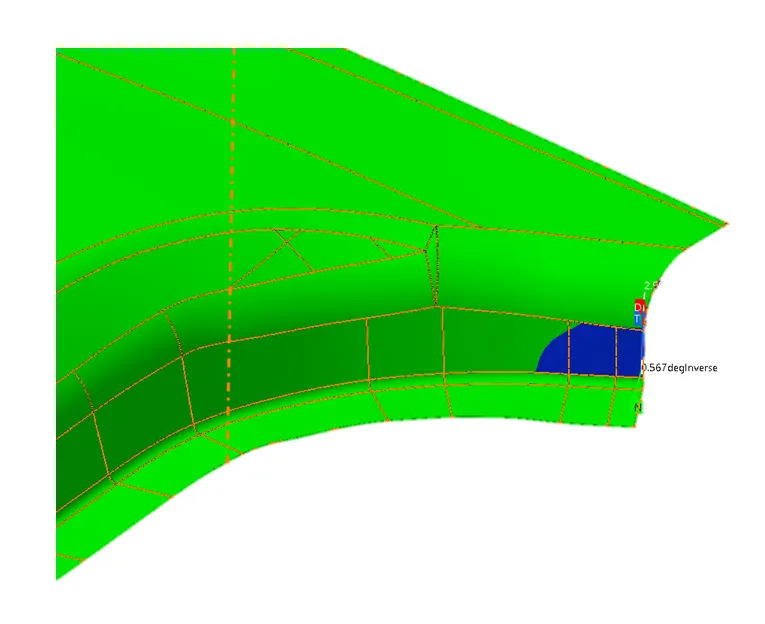
The minimum draft angle for the below face is 0.567 degrees.
CLASS B SURFACE CREATION
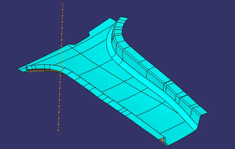
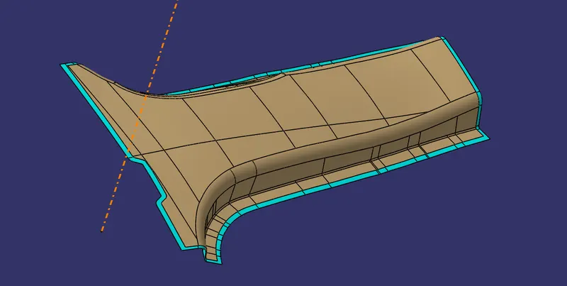
- Class B Surface is created by taking direct offset from class A surface. The surface in pink is the class b surface. Blue is class B and brown is a class A surface.
CLASS C SURFACE CREATION
- Using multiple extract command boundary of class A is extracted.
- Using extracted boundary we have used sweep command to form class C surface.
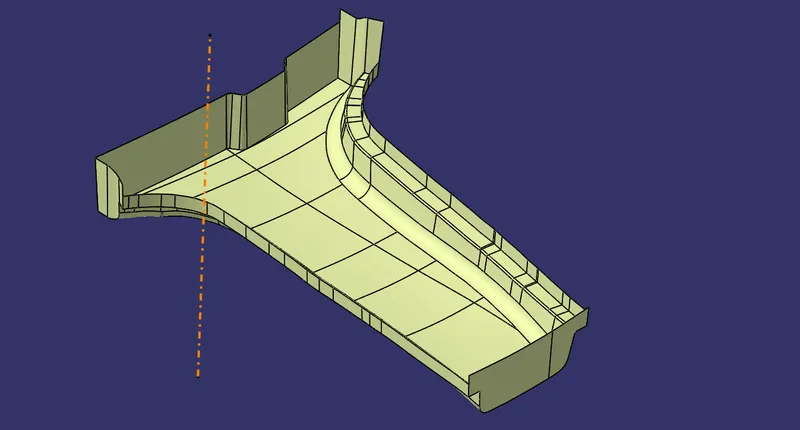
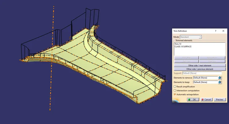
CLOSE BODY
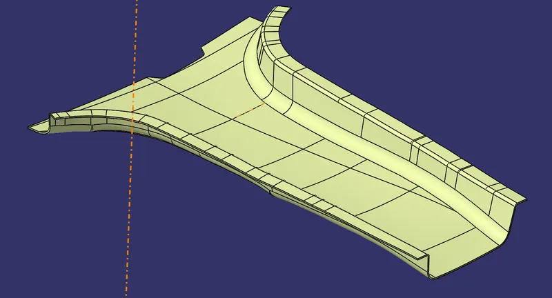
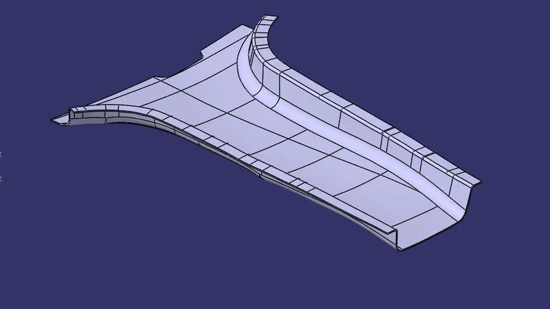
Class A and C body is trimmed together with class B body to get the complete body.
DOG HOUSE AND FOUR-WAY LOCATOR
- The thickness of the part is 2 mm, hence 40 % of 2 mm is equal to 0.8 mm which means c is equal to 0.8mm.
- The height of B is given as 3 mm.
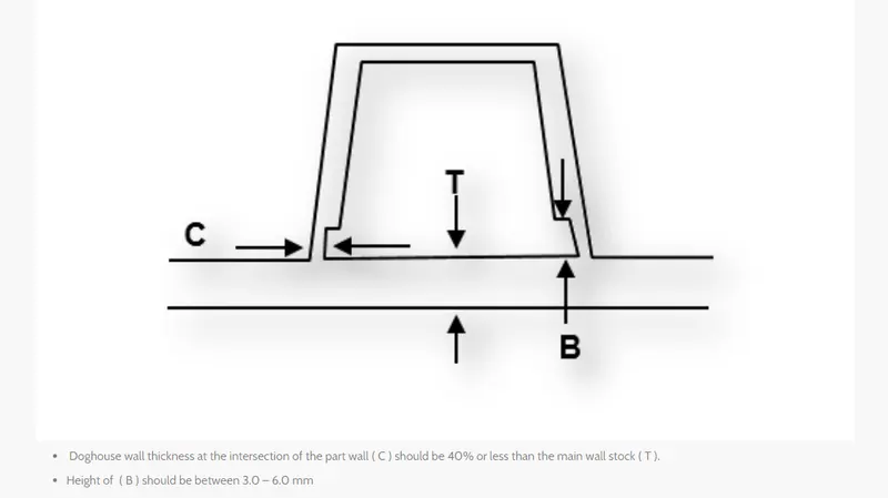
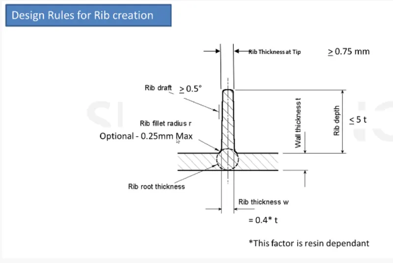
- The width of the rib is equal to 0.4 times the thickness of the part which is 0.8 mm.
- The four-way locator has a thickness of 0.8 mm.
- All the side ribs have a thickness of 1.5 mm because while giving the draft to the 0.8 mm thick rib it is forming sharp edges hence it is compensated to 1.5 mm.
- A draft of 0.5 mm is given to all the ribs.
RIBS
FINAL PART DRAFT ANALYSIS
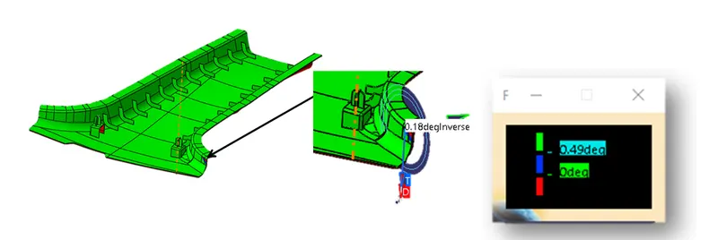
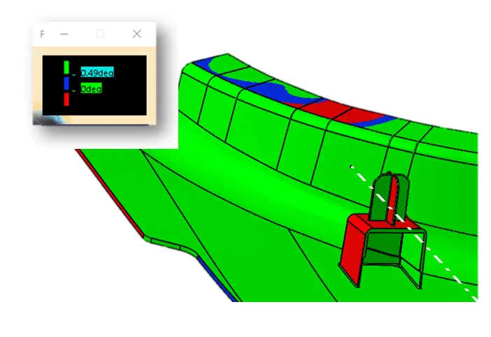
- As per the color scale, the minimum draft angle for all faces should be 0.49 degrees or above that. Inside the color scale, green shows a draft angle of 0.49 or above 0.49 degrees. Blue shows between 0 and 0.48 degrees. And red shows a negative draft angle. As per the above figure, some faces are green and some are blue hence our surface has cleared the draft analysis.
B Surface Draft Analysis with Main Tooling Axis
- The below Images show almost all the faces are having a minimum draft angle of 0.5 degrees except for some faces.
- Including all B side features ( Ribs, Dog House and 4-way locator)
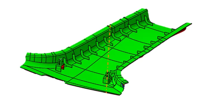
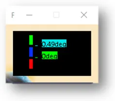
The minimum draft angle for the below face is 0.18 degrees.
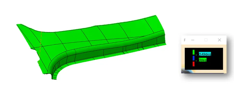
A and C Surface Draft Analysis with Main tooling axis
- The below Images show almost all the faces are having a minimum draft angle of 0.5 degrees.
- Includes Class A and Class C surfaces.
Dog House Draft Analysis with lifter Tooling axis
- From the draft analysis, we can see all the inside faces of the dog house are clearing the draft analysis with the side core tooling axis.
FINAL COMPONENT IN DIFFERENT ORIENTATION
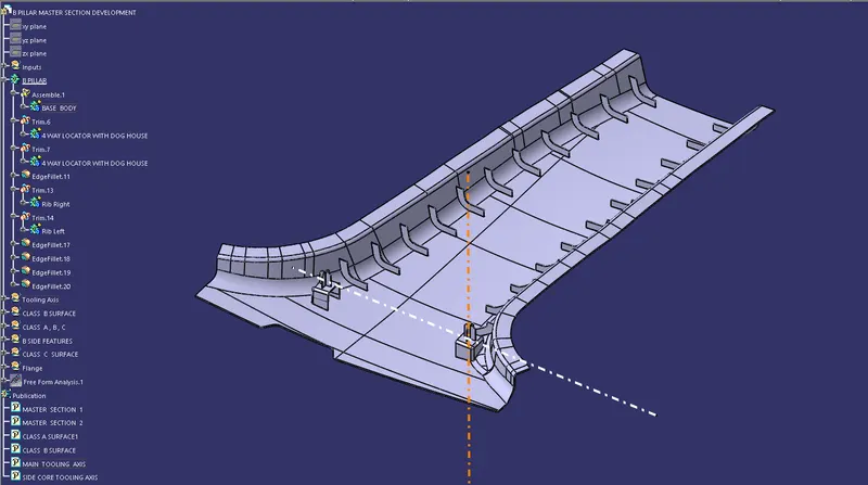
Isometric View
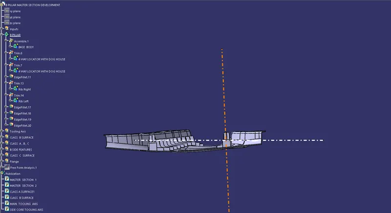
Front View
Side View
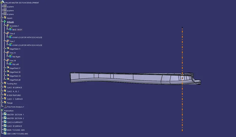
Top View