Photo Realistic Rendering
3D MODELING , ASSEMBLY AND PHOTOREALISTIC RENDERING OF AN AMERICAN CHOPPER
AIM - To Create 3D Model of an American Chopper
OBJECTIVES
- To 3D Model Parts of American Chopper
- To create Assembly of an American Chopper
- To create Photorealistic Rendering of an American Chopper
INTRODUCTION
- Solidworks - SolidWorks is a solid modeling computer-aided design and computer-aided engineering computer program published by Dassault Systèmes.
- American Chopper -A chopper is a type of custom motorcycle which emerged in California in the late 1950s. A chopper employs radically modified steering angles and lengthened forks for a stretched-out appearance. They can be built from an original motorcycle which is modified ("chopped") or built from scratch. Some of the characteristic features of choppers are long front ends with extended forks often coupled with an increased rake angle, hardtail frames (frames without rear suspension), very tall "ape hanger" or very short "drag" handlebars, lengthened or stretched frames, and larger than stock front wheels.The sissy bar , a set of tubes that connect the rear fender with the frame, and which are often extended several feet high, is a signature feature on many choppers.
DESIGN METHODOLOGY
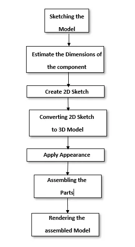
FEATURES USED
The major Features used in the solidworks for modeling the chopper are
- Creating 2D Sketch - 2D Sketch is created on XY , YZ Or XZ Plane. Using 2D Sketch we create 3D Features. Status of sketch can be determined by color codes. If sketch is black then it is fully defined , if sketch is blue then it is under defined and if it is red then it is called as over defined.
- Extruded Boss - Using this feature we can create solid which has the same boundries as that of the 2D Sketch that we are using for extrusion.
- Revolved Boss - To create ant cylindrical shape we used this feature. Inputs for creating revolve are 2D Sketch and Axis , along with we want revolve.
- Swept Boss - Inputs for this feature is any path and sketch perpendicular to that path. By following the path we create solid along with that path.
- Extruded Cut - Using this feature we can remove solid which has the same boundries as that of the 2D Sketch that we are using for extrusion cut.
- Lofted Boss - This feature is useful when we want to create solid with different cross sections along with guide curves. Inputs for this feature are cross section and guide curve.
- Fillet - This feature is commonly used. It is used for eliminating sharp edges.
- Chamfer - This feature is used to provide slope to the faces by eliminating edge.
- Circular Pattern - Using this feature we pattern the features along with circular edge.
- Mirror - It is used to copy the same feature across plane.
- Curve Driven Pattern - Using this we patttern the feature along with the curve which can be any profile.
- Draft - We used this feature to provide taper to the faces.
- Shell - This feature creates hollow section inside the geometry with certain thickness.
- Reference Geometry - Plane - This is very handy feature when we want to create any reference plane across the 3D Model.
- Curves - Project Curve , Composite Curve - Project curve combines two curves drawn in the different planes and produces one single curve. Using composite curve we can join two curves.
- Dome - This feature is used to create the spherical shape on the faces that we select.
- Split - It is used to cut the part across some sketch boundry and to remove that part from the main model.
- Combine - Using this feature we can Join two solid bodies and convert into one single body.
- Converting Entities - This feature is used when we want some reference onto 2D Sketch from another sketch drawn on different plane.
COMPONENTS
American chopper consists of
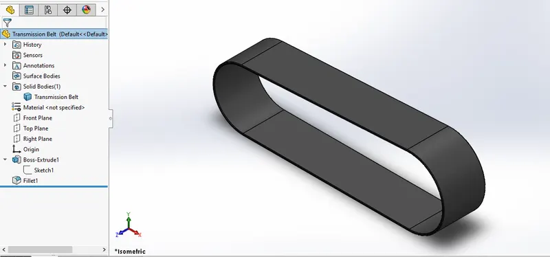
- Transmission Belt -Tools Used are extrusion , Fillet.
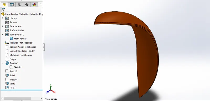
- Front Fender - Tools Used are Revolve , Split , fillet
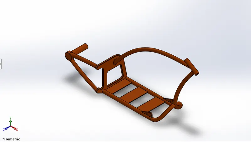
- Chassis - Tools Used are Revolve , Split , fillet, Extude cut , Extrude , sweep
- Rear Fender - Tools Used are Revolve , Split , fillet.
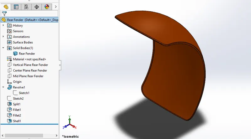
- Front Fork - Tools Used are Revolve , Mirror , fillet , chamfer.
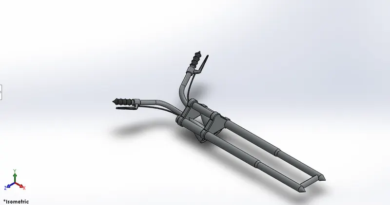
- Gas Tank - Tools Used are spline , surface Extrude , Split , Mirror , Knit Surface , Fillet.
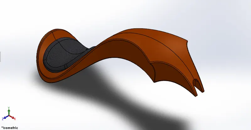
- Oil Tank - Tools Used are combine , extrude , shell.
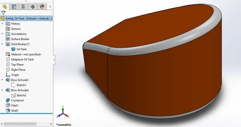
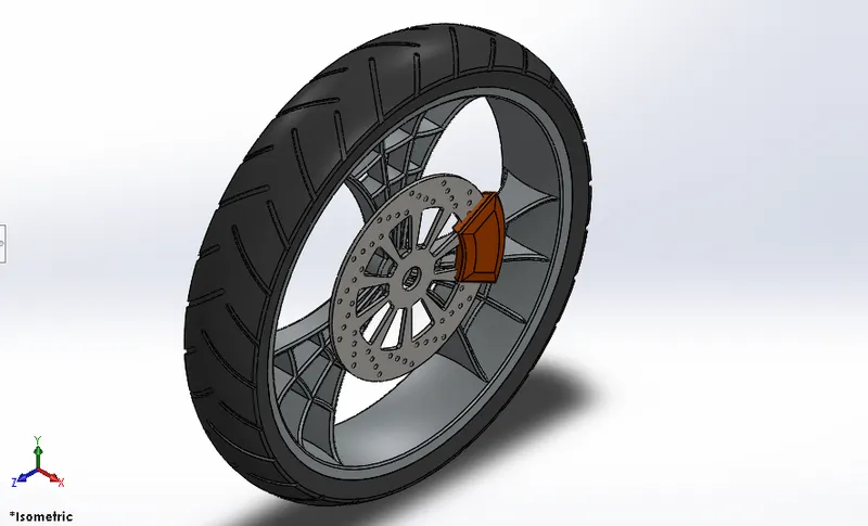
- Front wheel - Tools Used are Revolve , Chamfer , Circular Pattern , Extrude Cut , Fillet.
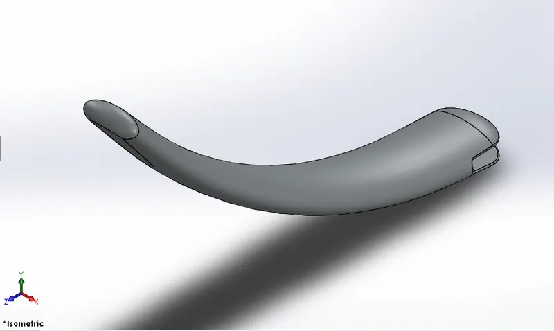
- Side Stand - Tools Used are Dome , Split , Extrude , Loft.
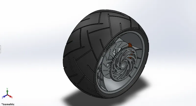
- Rear wheel - Tools Used are Revolve , Chamfer , Circular Pattern , Extrude Cut , Fillet.
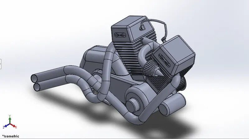
- Engine - Tools Used are Revolve , Chamfer , Linear Pattern , Extrude Cut , Fillet , Draft , Sweep , Circular Pattern , Revolve
- Pedal - Tools Used are Revolve , Chamfer , Linear Pattern , Fillet.
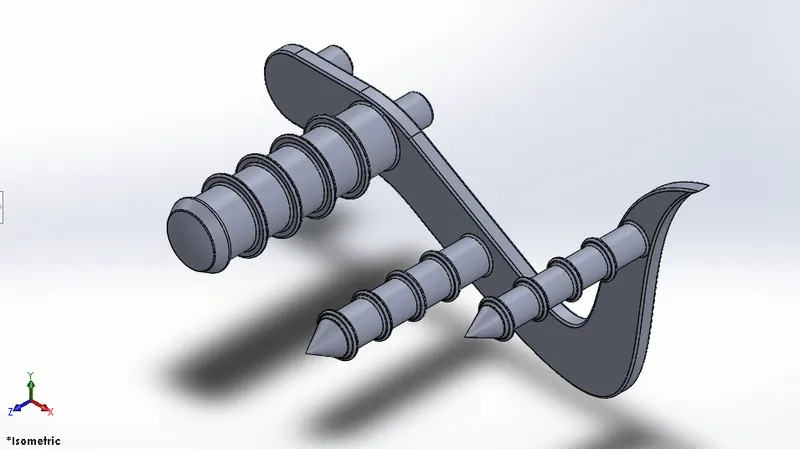
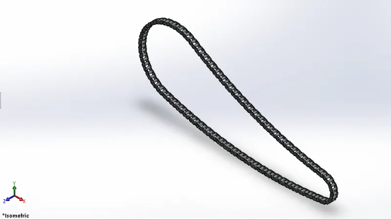
- Chain - Tools Used are Curve driven pattern , Block , Extrude.
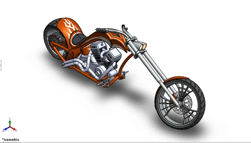
ASSEMBLY OF AN AMERICAN CHOPPER
- Isometric View
- Front View
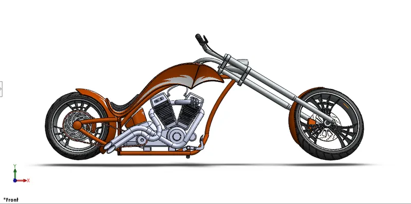
- Side View
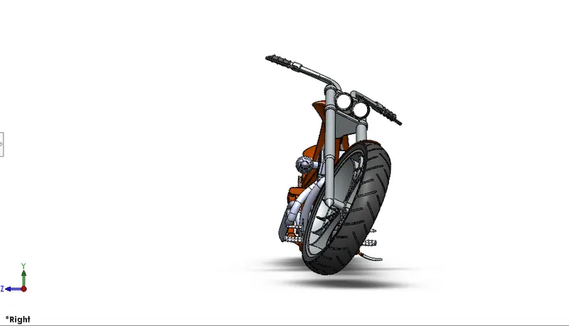
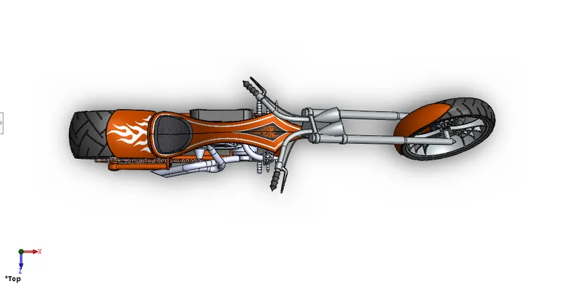
- Top View
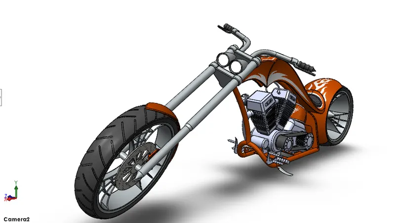
- Camera View
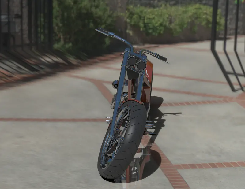
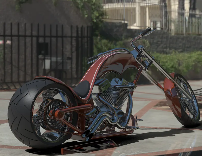
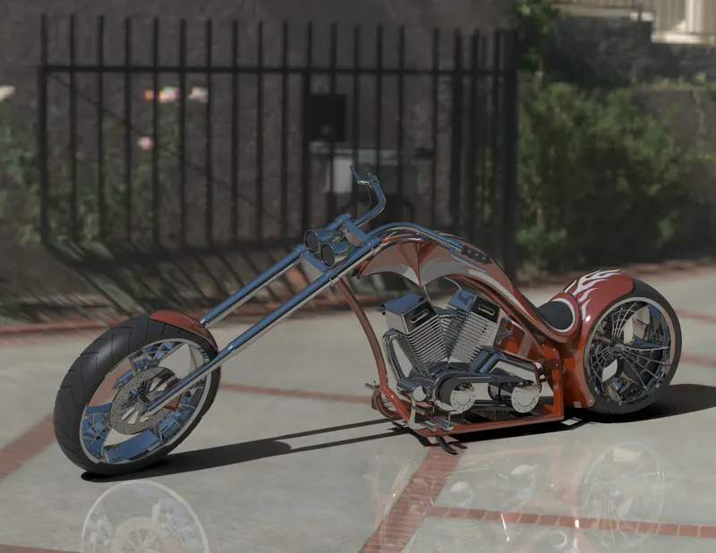
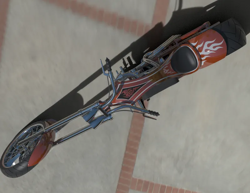
RENDERING IMAGES OF AMERICAN CHOPPER
CONCLUSION
I have successfully learnt the solid modeling , surface modeling features and also rendeing techniques used in photoview 360 and solidworks visualize.