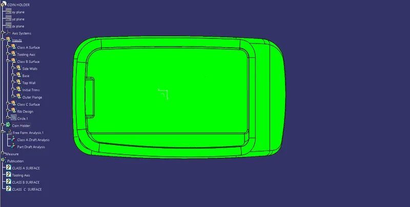
Week 9 - Attachment Feature Creation - Challenge 1
RIB DESIGN
Fully Defined Sketch
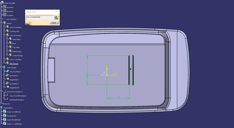
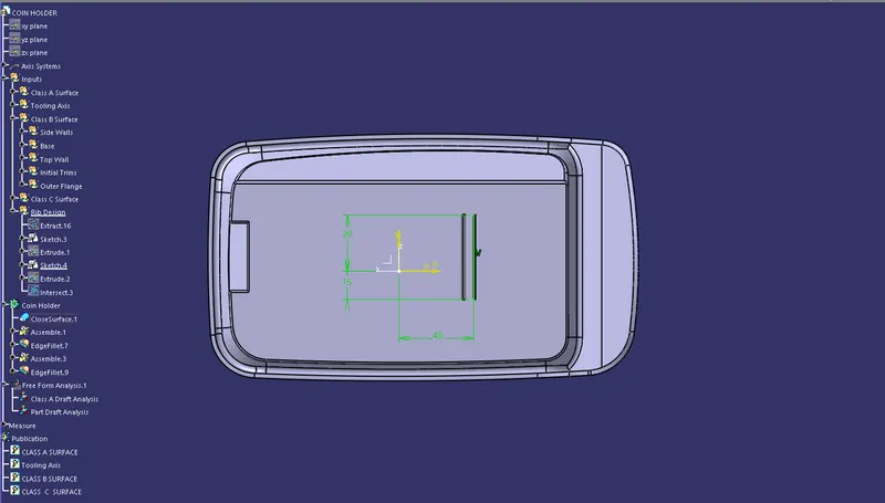
Design Of Rib With Rules
1.Maximum Height of the rib should be 5 times the thickness of the plastic component.
As thickness of the plastic component is 2.5 mm hence maximum height = 2.5 x 5 = 12.5 mm
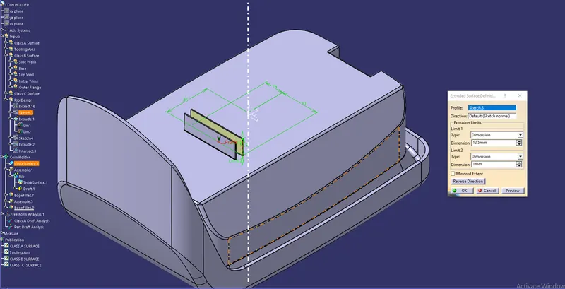
2.Rib thickness at the base should be 0.4 times the thickness of the plastic component.
Hence Rib thickness at the base = 0.4 * 2.5 = 1 mm
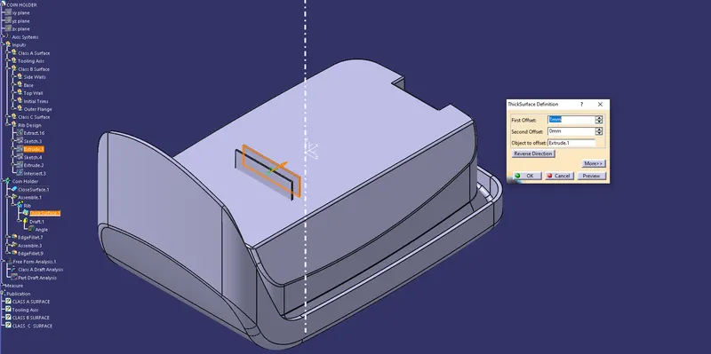
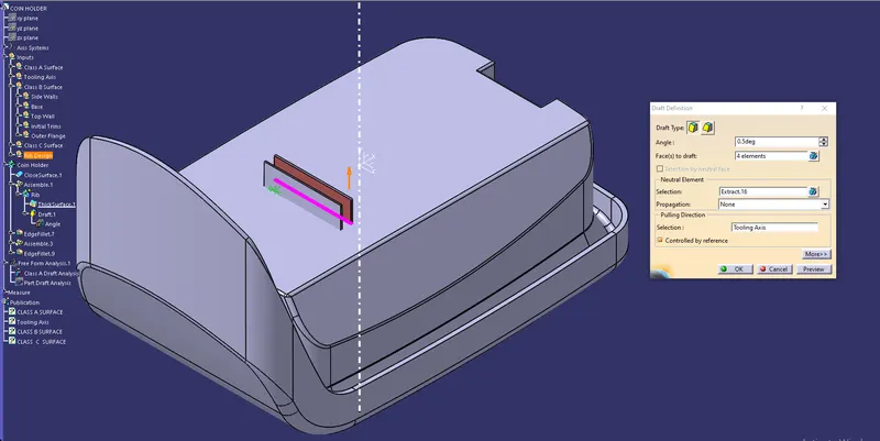
3.Minimum Draft angle should be at least 0.5 degrees for rib faces.
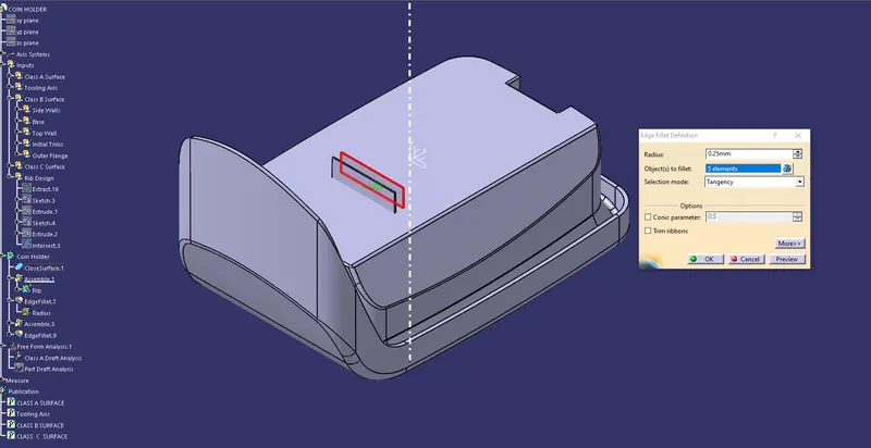
4.Maximum fillet thickness for all the draft edges should be 0.25 mm.
5.Minimum Rib Thickness at Tip should be 0.75 mm
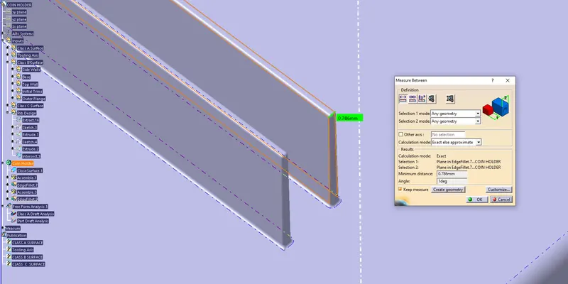
6.Ratio of height of rib to the distance between two ribs should be less than 3 mm.
Height of Rib = 12.5 mm
Distance Between Two Ribs = 5 mm
Ratio = 12.5 / 5 = 2.5
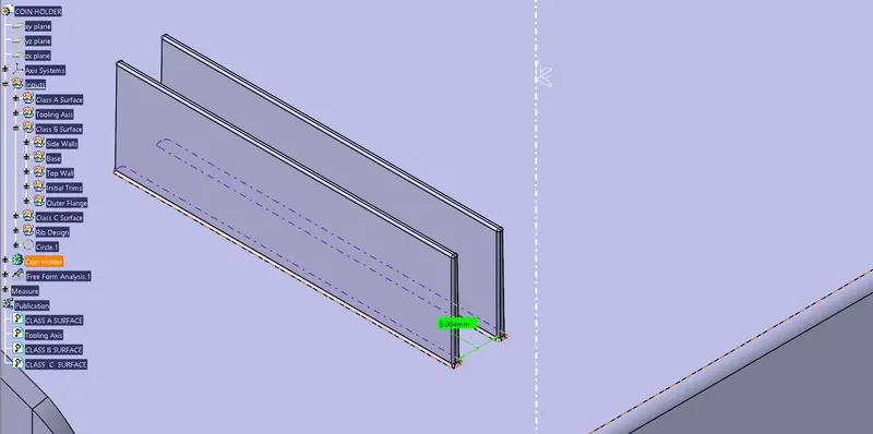
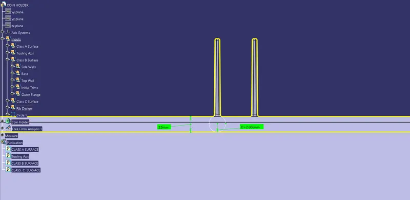
7.Rib Root Thickness Analysis
Rib Root Thickness should be equal to or less than 30% of the Thickness of the plastic component.
30% of thickness of the component = 3.25 mm
As per Figure , Rib root thickness = 2.686 mm which is less than 3.25 mm . Hence it satisfies the rule.
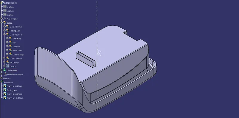
COMPLETE DESIGN IN VARIOUS ORIENTATION
Isometric View
Front View
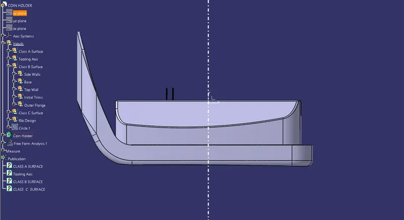
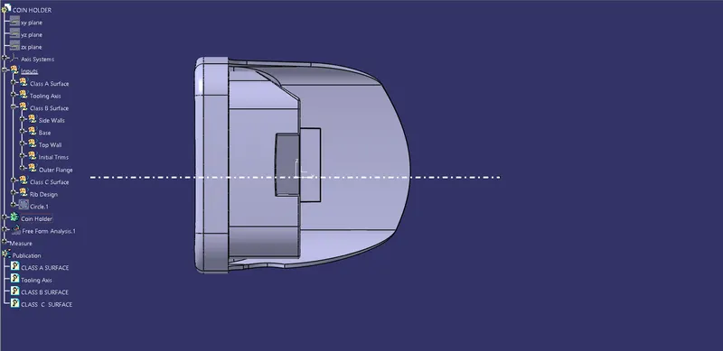
Side View
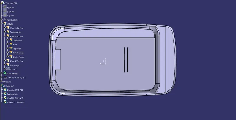
Top View
DRAFT ANALYSIS OF SOLID PART
- Using insert command draft analysis tool has opened.
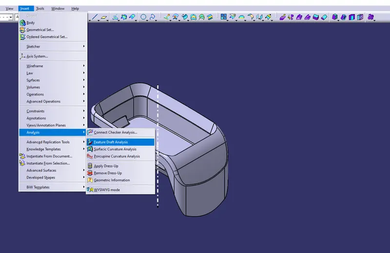
- By clicking on feature draft analysis two pallets opened. One pallet has necessary draft analysis commands and other one is color range which shows the draft values range in form of color.
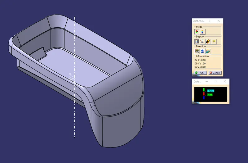
- Inside the draft analysis command window we have selected compass option to create a compass.
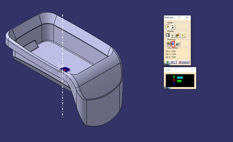
- We have drag the compass onto the component and aligned with the tooling axis and locked using lock command.
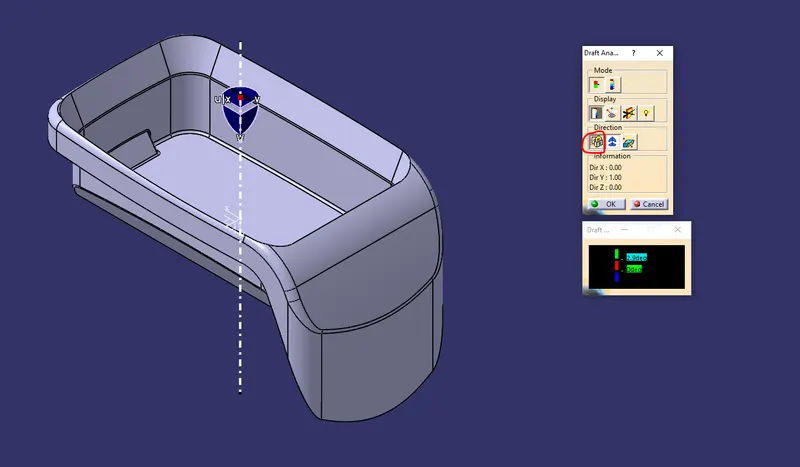
- Now by dragging the mouse pointer anywhere on the component and clicking on it will show us the required draft analysis.
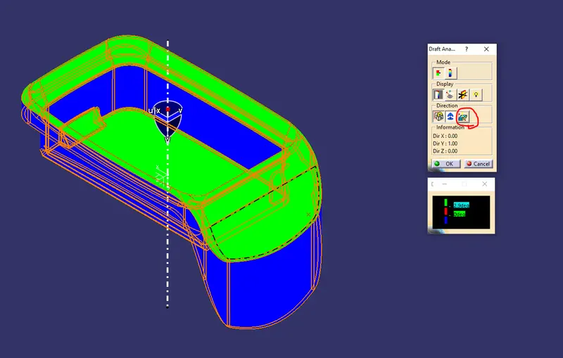
- As per color scale minimum draft angle for all faces should be 2.99 degrees or above that. Inside the color scale green shows draft angle 2.9 or above 2.9 degress. Red shows between 0 and 2.88 degrees. And blue shows negative draft angle. As per the above figure some faces are green and some are blue hence our part has not cleared the draft analysis. And ribs are coming below the B surface hence anyhow they will not clear draft analysis.
3D VIEWS OF COMPONENT WITH DRAFT ANALYSIS COLOR CODE
Isometric view
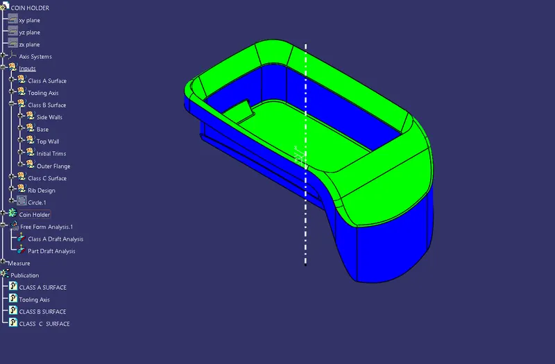
Front View
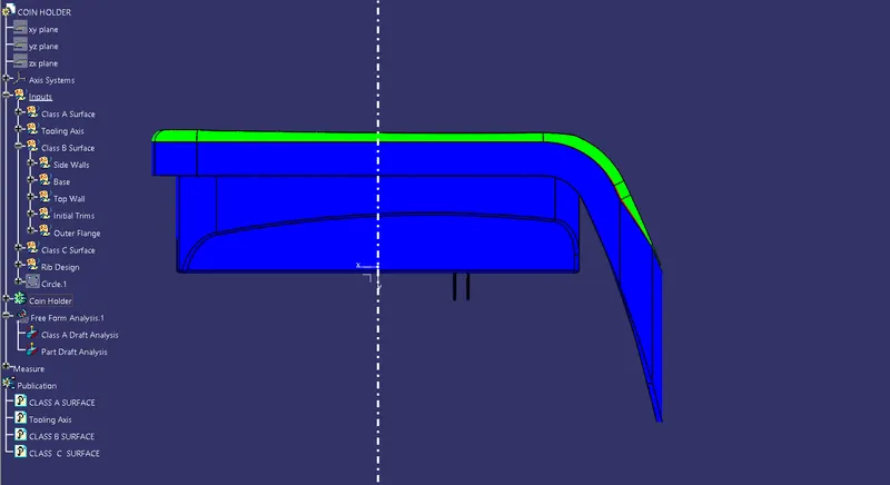
Side View
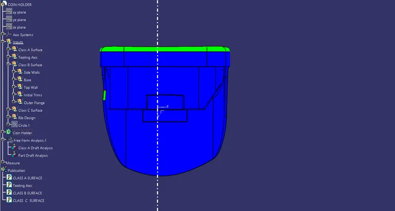
Top View