Radar Mast & Final Assembly of Yacht
3D MODELING , ASSEMBLY AND PHOTOREALISTIC RENDERING OF SUNSEEKER PREDATOR YACHT
AIM - To Create 3D Model of an Sunseeker Predator Yacht
OBJECTIVES
- To 3D Model Parts of Sunseeker Predator Yacht
- To create Assembly of an Sunseeker Predator Yacht
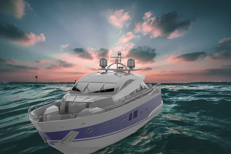
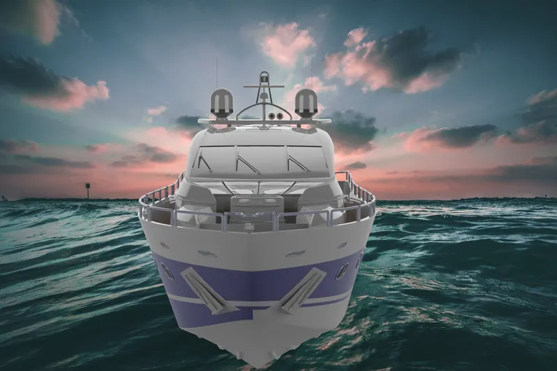
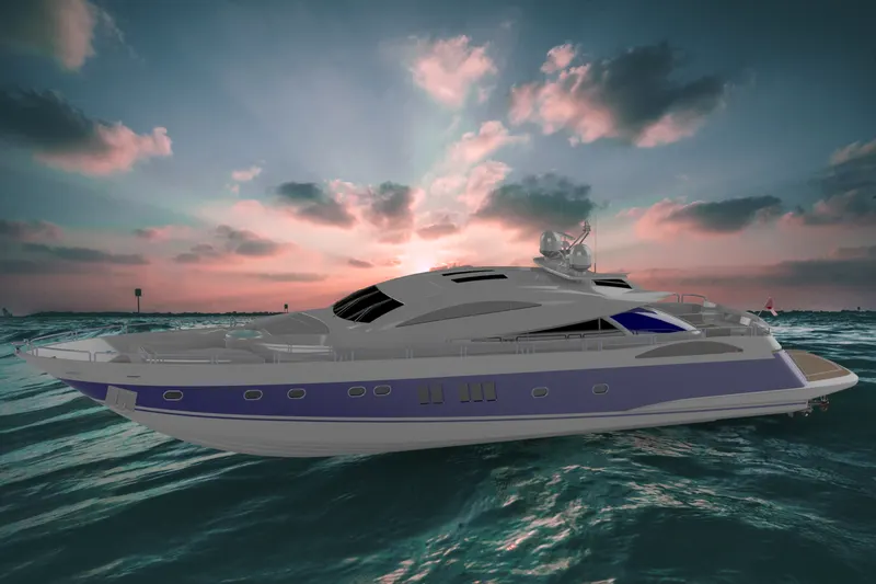
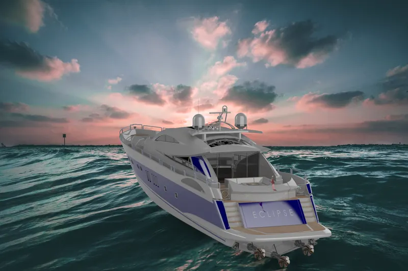
- To create Photorealistic Rendering of an Sunseeker Predator Yacht
INTRODUCTION
- Solidworks - SolidWorks is a solid modeling computer-aided design and computer-aided engineering computer program published by Dassault Systèmes.
- Sunseeker Predator Yacht - Sunseeker International is a British luxury performance motor yacht brand. Originally named Poole Power Boats, the company was founded by brothers Robert and John Braithwaite in 1969. The company changed its name to Sunseeker International in 1985 and has since become a global icon. Sleek and powerful, it’s the perfect blend of power and poise. Accommodating eight guests and three crew, the impressive interior is stylish yet purposeful, with an outstanding level of comfort and only the most exclusive materials featuring throughout. Sitting beneath the vast sliding hardtop roof is the main saloon and cockpit. When opened, natural light illuminates the interior allowing guests to indulge in the lavish surroundings. The cockpit features a blend of contemporary style, design and modern technologies, while the flybridge is just as sumptuous and innovative. Rarely overshadowed, never outrun. It leaves all others in its wake.
DESIGN METHODOLOGY
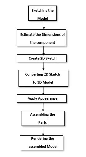
FEATURES USED
The major Features used in the solidworks for modeling the chopper are
- Creating 2D Sketch - 2D Sketch is created on XY , YZ Or XZ Plane. Using 2D Sketch we create 3D Features. Status of sketch can be determined by color codes. If sketch is black then it is fully defined , if sketch is blue then it is under defined and if it is red then it is called as over defined.
- Surface Extrude - Using this any 2D sketch such as line can be extruded to create a surface.
- Knit Surface - Using this two or more than two surfaces can be joined and converted into single surface.
- Trim Surface - We can trim the surfaces to remove the excess portion which we don't want.
- Extend Surface - We can extend the surface using its edge.
- Fill Surface - Using this we can create the surface in close boundry.
- Spline - This is the major command in 2D Sketch that we used while surfacing any component. We can create the smooth curve using this command and can control the curvature using its control points.
- Extruded Boss - Using this feature we can create solid which has the same boundries as that of the 2D Sketch that we are using for extrusion.
- Revolved Boss - To create ant cylindrical shape we used this feature. Inputs for creating revolve are 2D Sketch and Axis , along with we want revolve.
- Swept Boss - Inputs for this feature is any path and sketch perpendicular to that path. By following the path we create solid along with that path.
- Extruded Cut - Using this feature we can remove solid which has the same boundries as that of the 2D Sketch that we are using for extrusion cut.
- Lofted Boss - This feature is useful when we want to create solid with different cross sections along with guide curves. Inputs for this feature are cross section and guide curve.
- Fillet - This feature is commonly used. It is used for eliminating sharp edges.
- Chamfer - This feature is used to provide slope to the faces by eliminating edge.
- Mirror - It is used to copy the same feature across plane.
- Linear Pattern - Using this we patttern the feature along with the line.
- Reference Geometry - Plane - This is very handy feature when we want to create any reference plane across the 3D Model.
- Curves - Project Curve , Composite Curve - Project curve combines two curves drawn in the different planes and produces one single curve. Using composite curve we can join two curves.
- Dome - This feature is used to create the spherical shape on the faces that we select.
- Converting Entities - This feature is used when we want some reference onto 2D Sketch from another sketch drawn on different plane.
COMPONENTS
Sunseeker Predator Yacht consists of
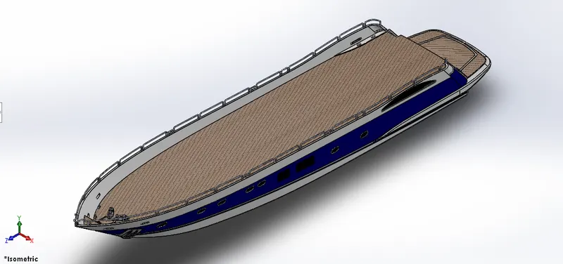
- Hull - Major Tools Used are spline , extrude surface , Mirror , knit surface
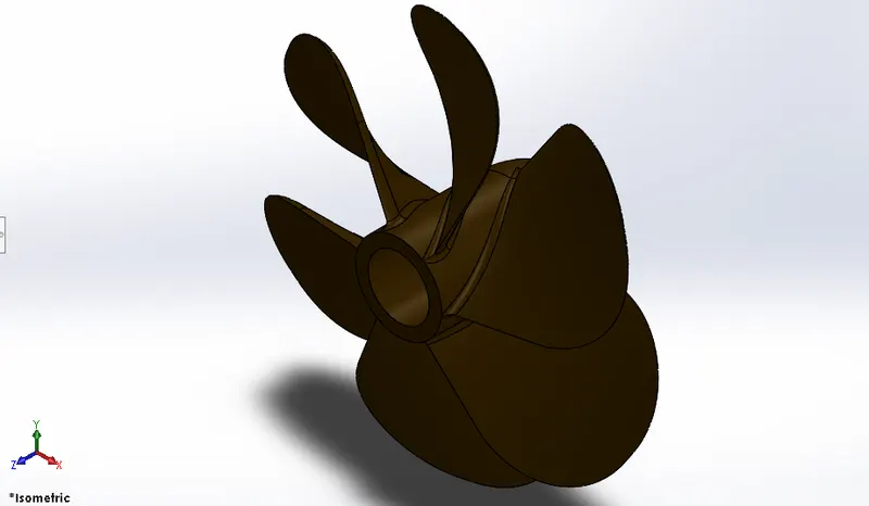
- Propeller - Major Tools Used are Revolve , fillet , extruded cut
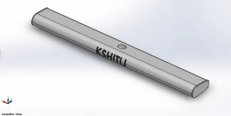
- Radar - Tools Used are Extrude , fillet , extruded cut.
- Garage door - Major Tools Used are Extrude , Fillet , Shell
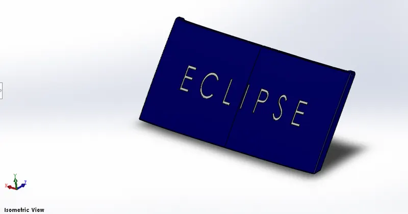
- Radar Mast - Major Tools Used are Extrude , fillet , chamfer , revolve , sweep.
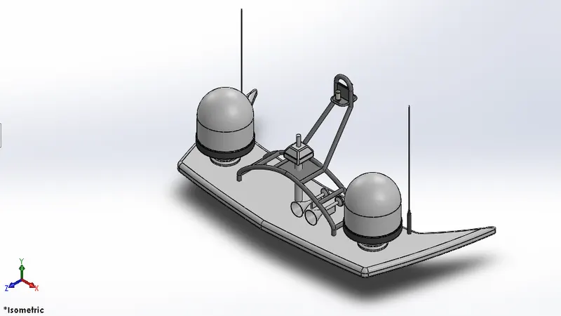
- Superstructure - Major Tools Used are spline , extrude surface , Mirror , knit surface
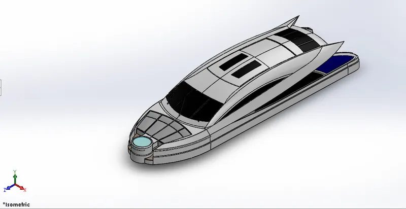
- Front Seat - Major Tools Used are Extrude , fillet , chamfer , Mirror
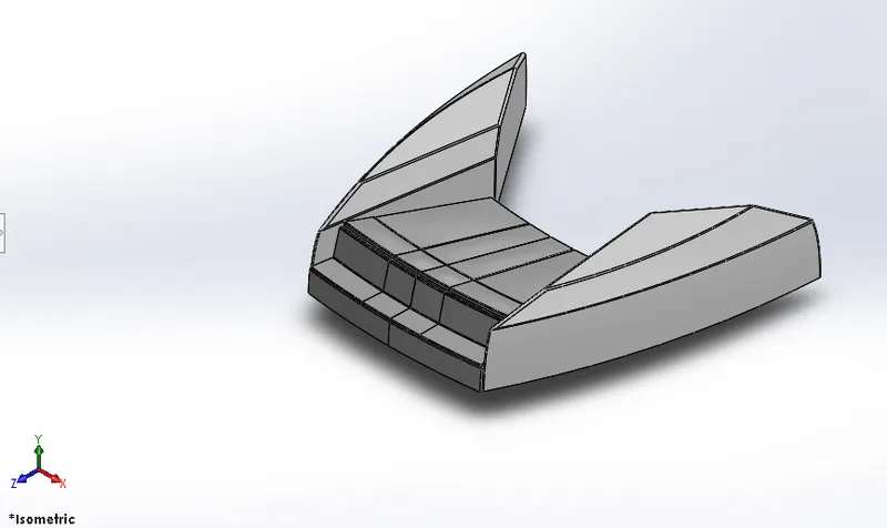
- Middle Seat - Major Tools Used are Extrude , fillet , chamfer , Mirror
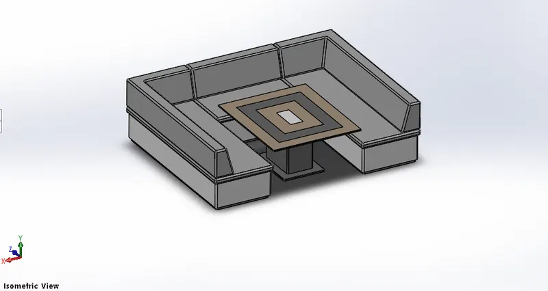
- Major Tools Used are Extrude , fillet , chamfer , Mirror , Extrude Cut , Sweep
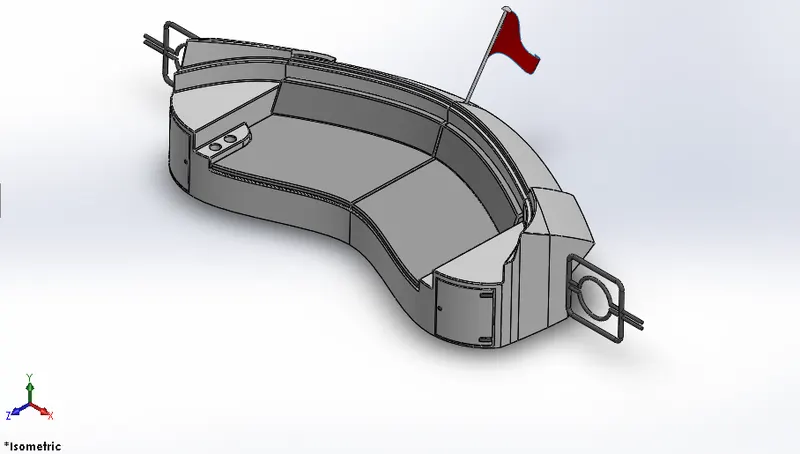
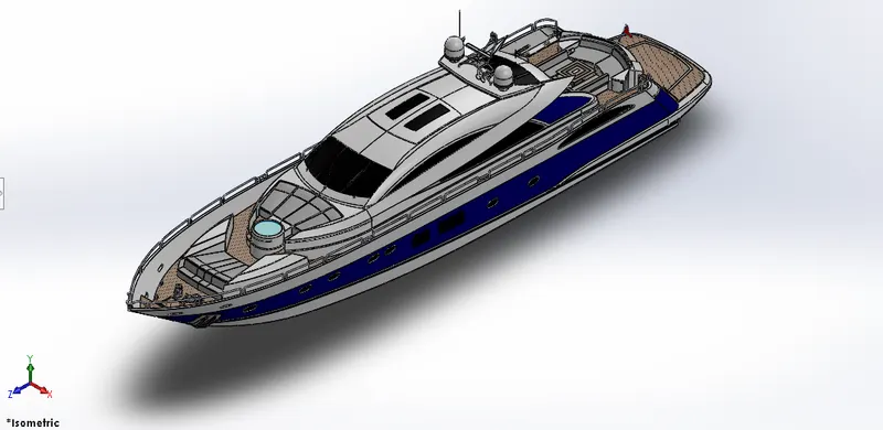
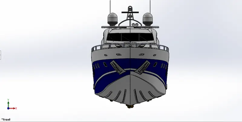
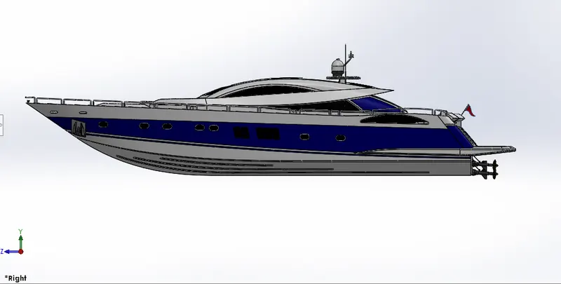
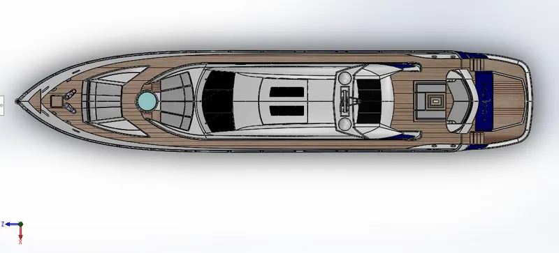
ASSEMBLY OF AN SUNSEEKER PREDATOR YACHT
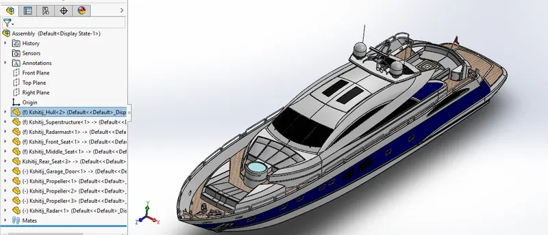
- Feature Tree
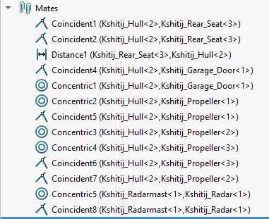
- Mates
- Isometric View
- Front View
- Side View
- Top View
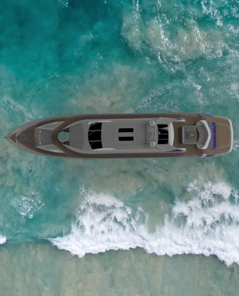
RENDERING IMAGES OF SUNSEEKER PREDATOR YACHT
CONCLUSION
I have successfully learnt the surface modeling , solid modeling features and also rendeing techniques used in photoview 360 and solidworks visualize.