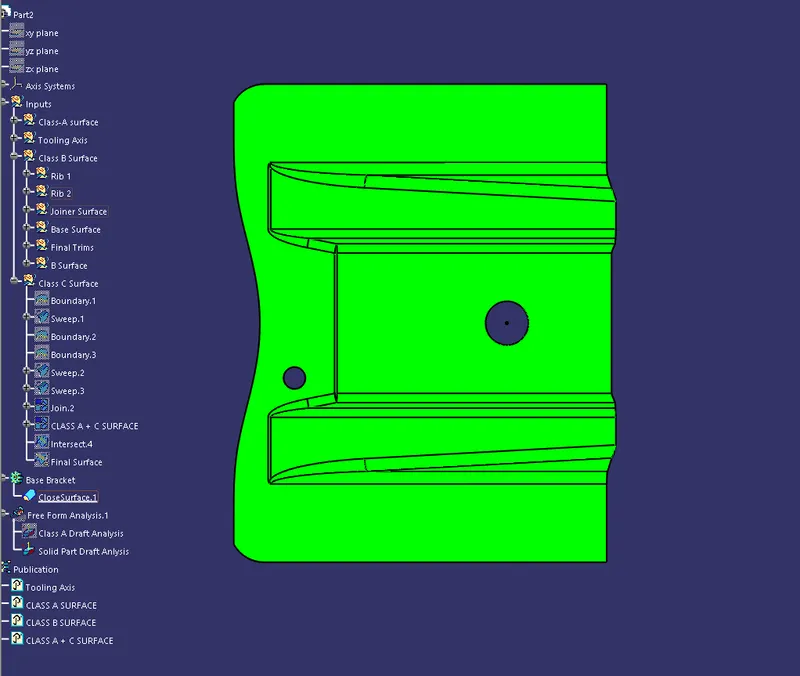
Week 8 - Challenge 2 - Base Bracket Design
TOOLING AXIS CREATION
- Selection for direction of tooling axis depends on ease at which components can be easily ejected.
- For Base Bracket surface point has been created using point command which is the center of the top hole.
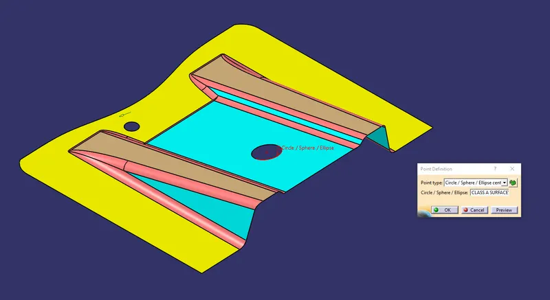
- Axis system at this point has been created which has same directions as that of current axis system.
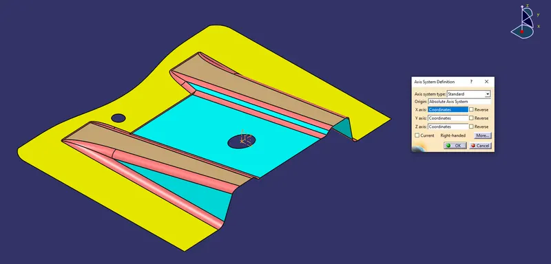
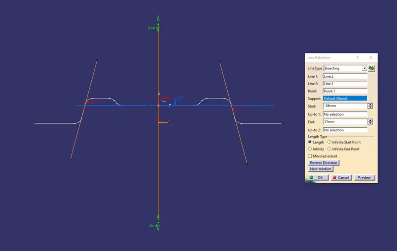
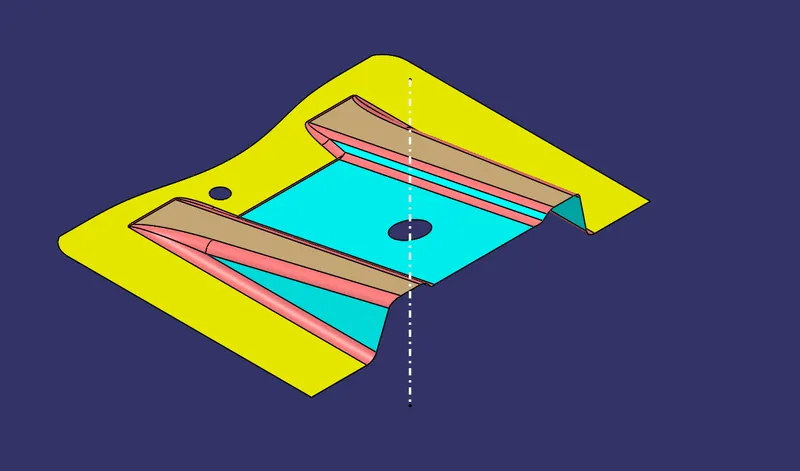
- By analyzing the component tooling axis can be formed in a z direction which will make the component easily ejected.
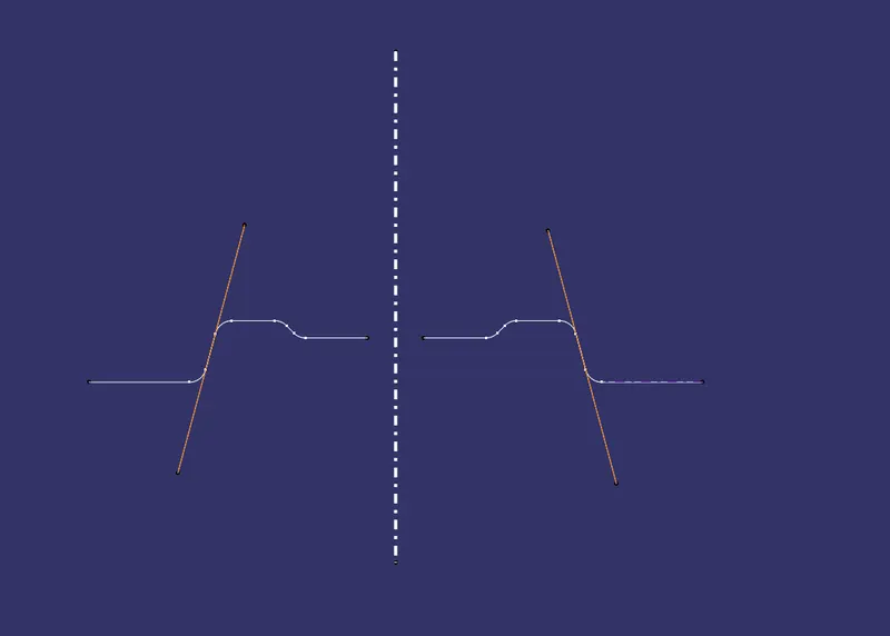
- To make the tooling axis , we have intersected the z-x plane with fan cover surface to get the desired sketch of intersection.
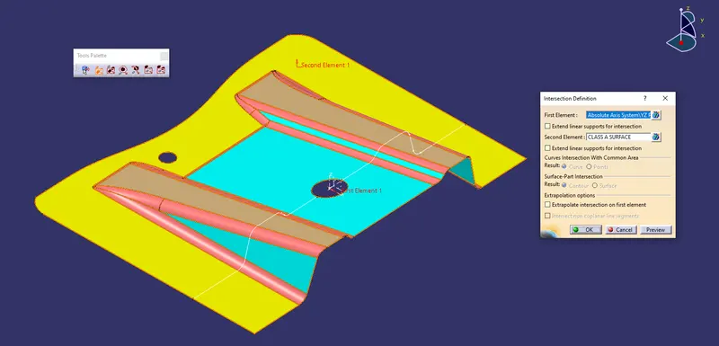
- Using sketch of intersection two lines passing through inclined surface were created using point-point line creation command.
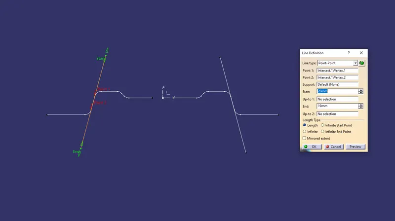
- Then with these two lines tooling axis has created using bisecting line creation command.
DRAFT ANALYSIS OF CLASS A SURFACE
- After creation of tooling axis , draft analysis has been performed.
- Using insert command draft analysis tool has opened.
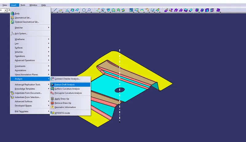
- By clicking on feature draft analysis two pallets opened. One pallet has necessary draft analysis commands and other one is color range which shows the draft values range in form of color.
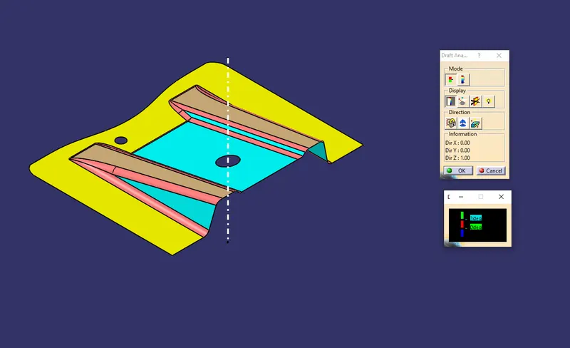
- Inside the draft analysis command window we have selected compass option to create a compass.
- Compass is created away from the component.
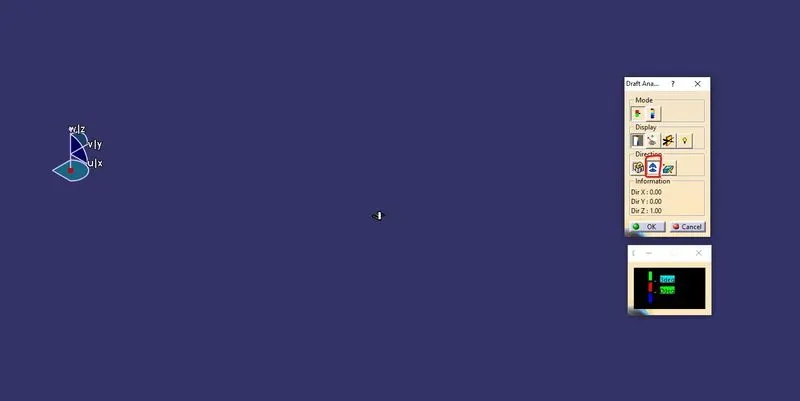
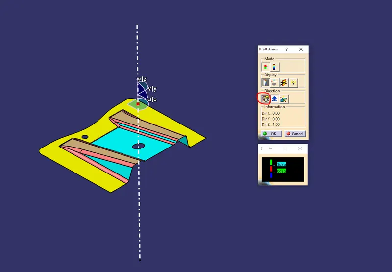
- We have drag the compass onto the component and aligned with the tooling axis and locked using lock command.
- Now by dragging the mouse pointer anywhere on the component and clicking on it will show us the required draft analysis.
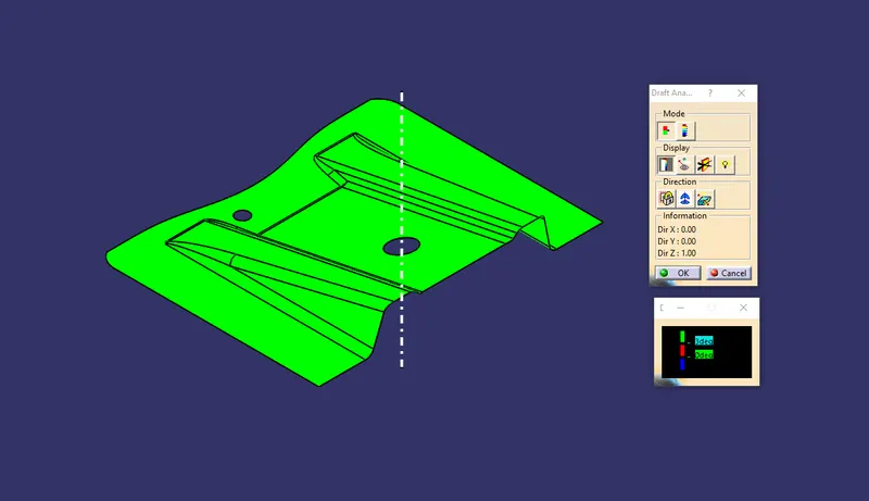
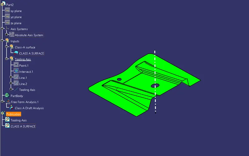
- As we know minimum draft angle for all faces of plastic component should be 3 degrees. Inside the color scale green shows draft angle 3 or above 3 degress. Red shows between 0 and 3 degrees. And blue shows negative draft angle. As per the above figure all faces are green hence our product has successfully cleared the draft analysis.
3D VIEWS OF CLASS A SURFACE WITH DRAFT ANALYSIS COLOR CODE
Isometric view
Front View
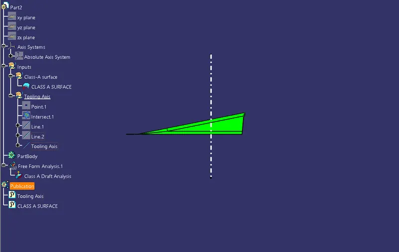
Side View
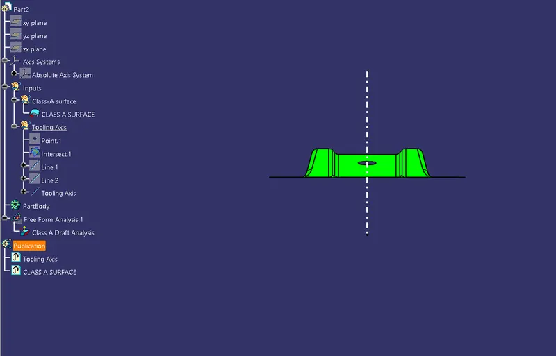
Top View
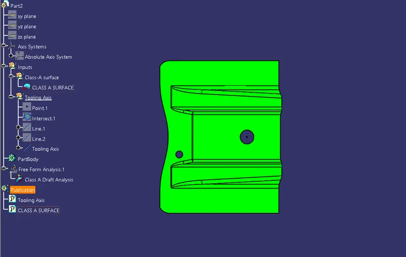
DRAFT ANALYSIS OF SOLID PART
- After creation of tooling axis , draft analysis has been performed.
- Using insert command draft analysis tool has opened.
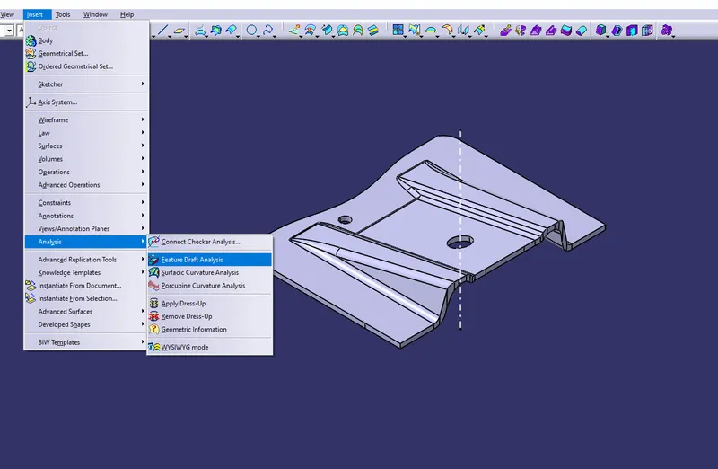
- By clicking on feature draft analysis two pallets opened. One pallet has necessary draft analysis commands and other one is color range which shows the draft values range in form of color.
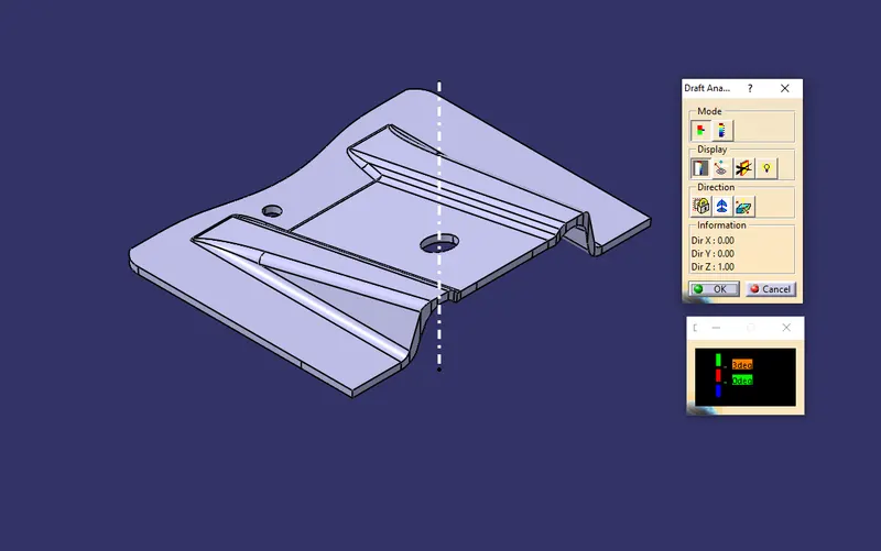
- Inside the draft analysis command window we have selected compass option to create a compass.
- Compass is created away from the component.
- We have drag the compass onto the component and aligned with the tooling axis and locked using lock command.
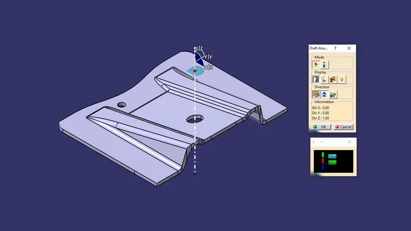
- Now by dragging the mouse pointer anywhere on the component and clicking on it will show us the required draft analysis.
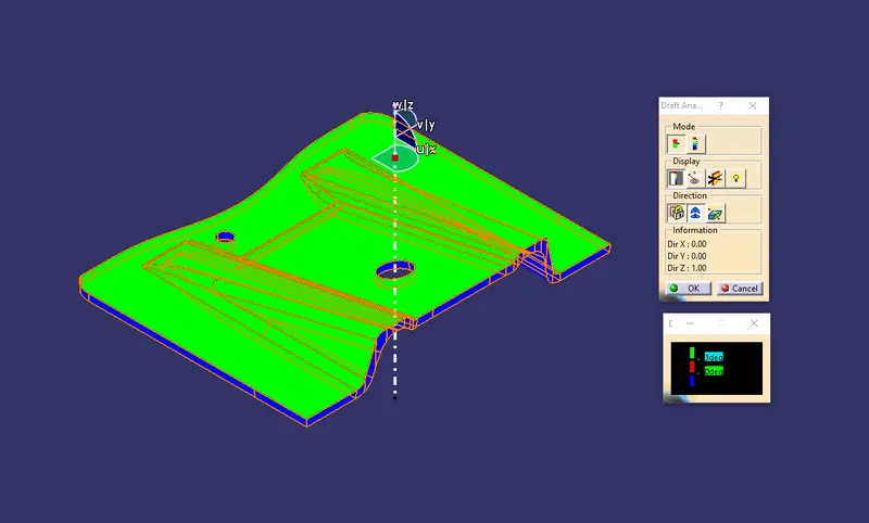
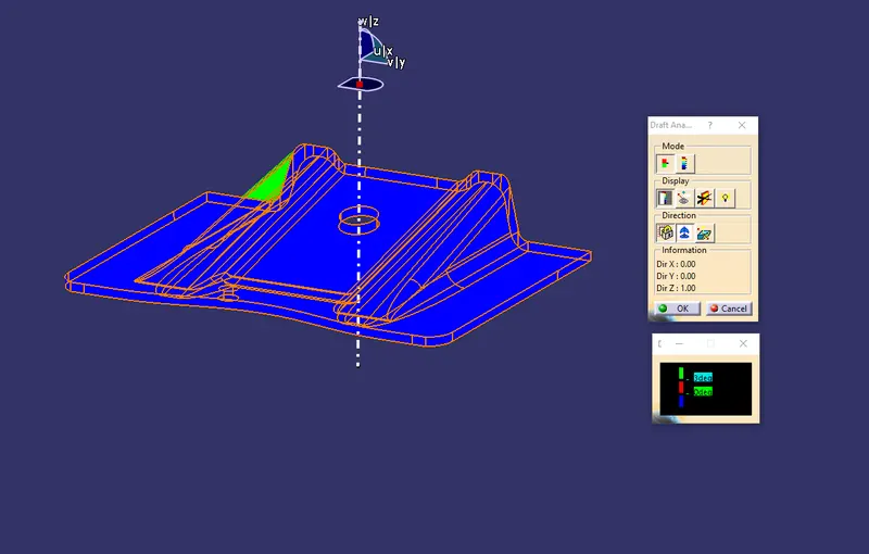
- As we know minimum draft angle for all faces of plastic component should be 3 degrees. Inside the color scale green shows draft angle 3 or above 3 degress. Red shows between 0 and 3 degrees. And blue shows negative draft angle. As per the above figure above faces are green and side faces and bottom faces are coming blue which means parting line will lie coincident to green face. Hence our product has successfully cleared the draft analysis.
3D VIEWS OF COMPONENT WITH DRAFT ANALYSIS COLOR CODE
Isometric view
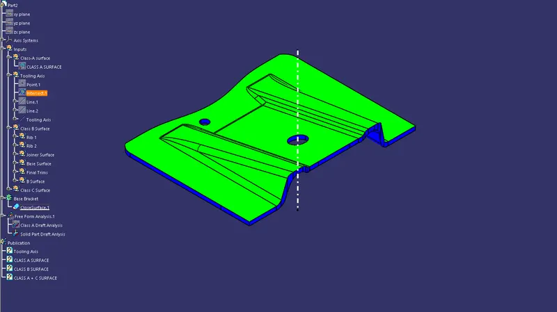
Front View
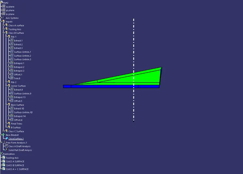
Side View
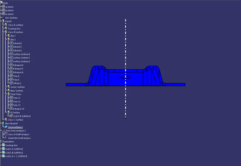
Top View