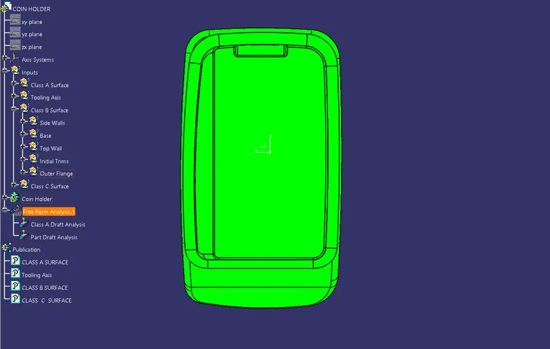
Week 8 - Challenge 4 - Coin Holder Design
TOOLING AXIS CREATION
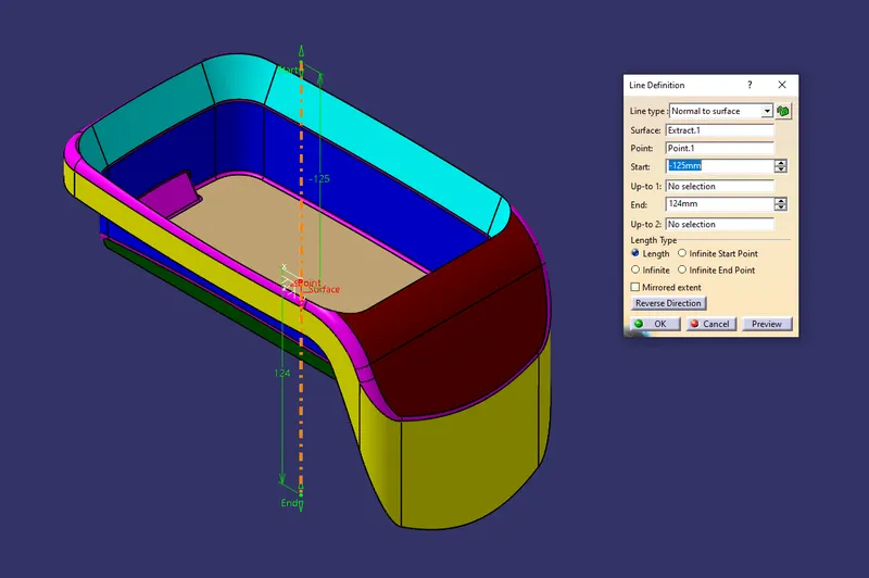
- We always make tooling axis with respect to Circle or Bin. In coin holder bin is present hence we take it as reference for creating tooling axis.We have extracted base of bin.
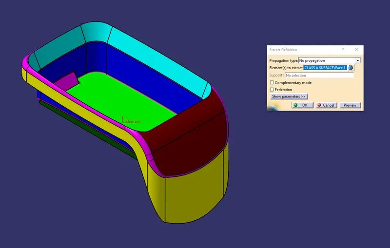
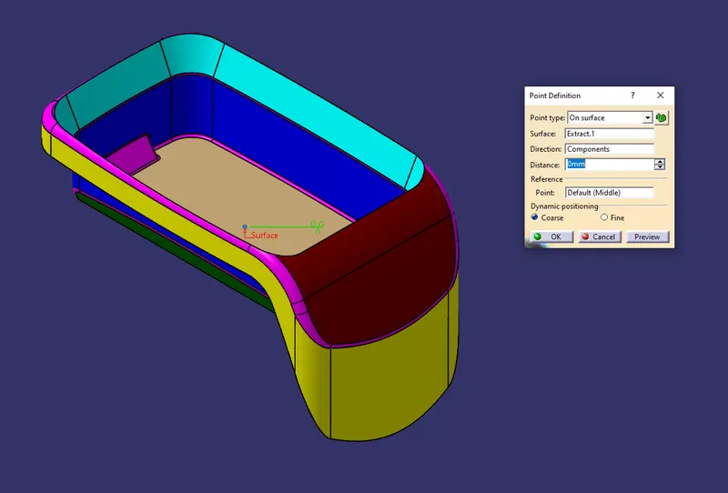
- For coin holder base surface point has been created using point command which is the center of the surface.
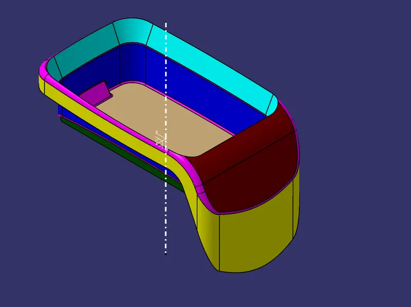
- Axis system at this point has been created which has same directions as that of current axis system.
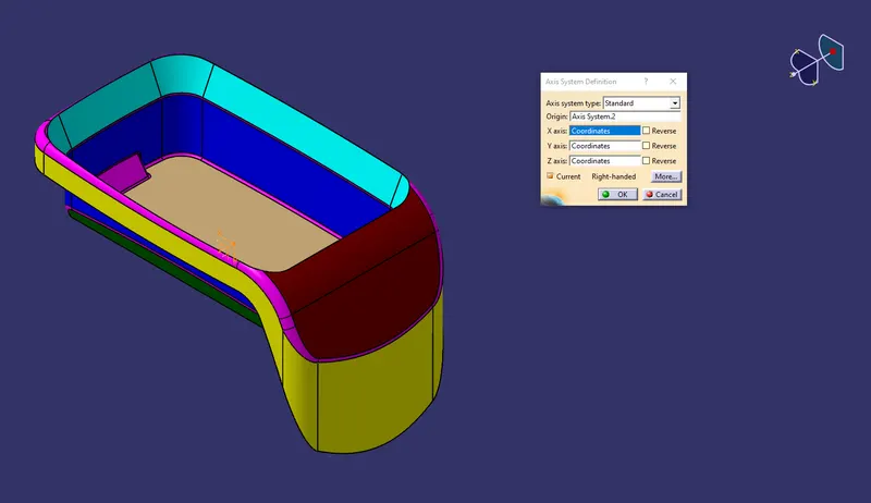
- As per observation three walls of bin are not having any draft angle , they are flat , so anyhow they will fail in draft analysis. So , we have made the tooling axis perpendicular to the base of bin.
DRAFT ANALYSIS OF CLASS A SURFACE
- After creation of tooling axis , draft analysis has been performed.
- Using insert command draft analysis tool has opened.
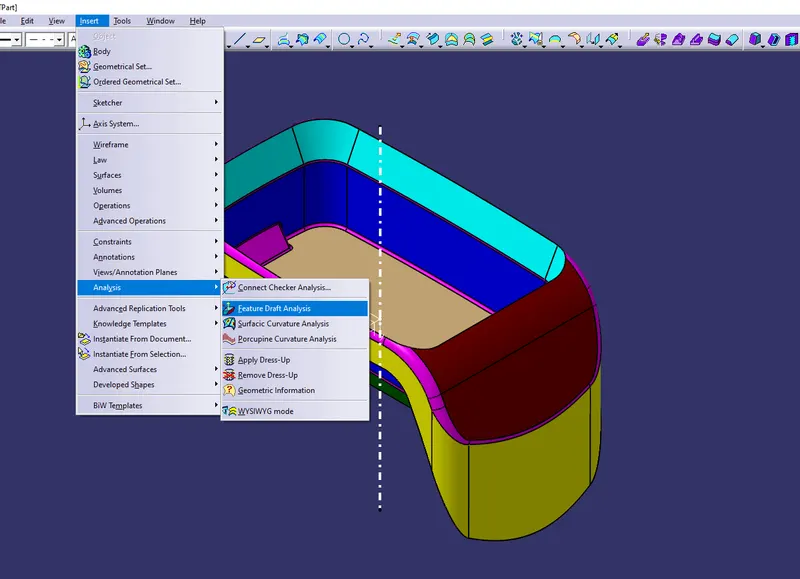
- By clicking on feature draft analysis two pallets opened. One pallet has necessary draft analysis commands and other one is color range which shows the draft values range in form of color.
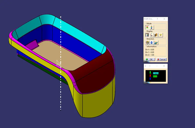
- Inside the draft analysis command window we have selected compass option to create a compass.
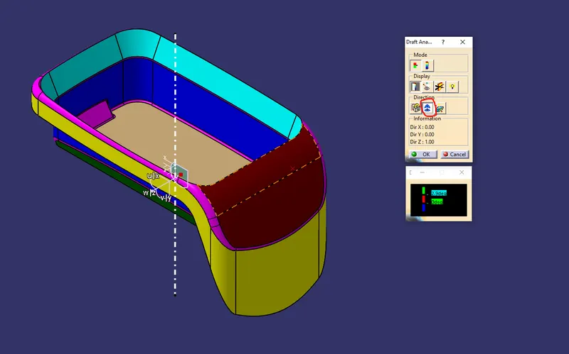
- We have drag the compass onto the component and aligned with the tooling axis and locked using lock command.
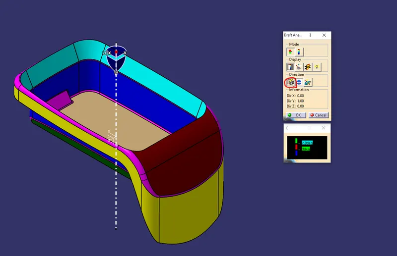
- Now by dragging the mouse pointer anywhere on the component and clicking on it will show us the required draft analysis. As compass is inverted hence we used inverse draft analysis command to get required draft analysis.
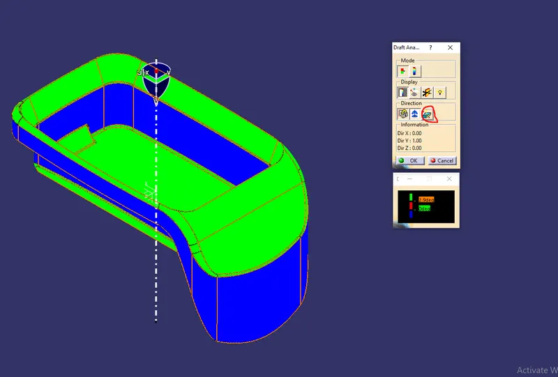
- As per color scale minimum draft angle for all faces should be 2.99 degrees or above that. Inside the color scale green shows draft angle 2.9 or above 2.9 degress. Red shows between 0 and 2.88 degrees. And blue shows negative draft angle. As per the above figure some faces are green and some are blue hence our surface has not cleared the draft analysis. We have to contact the class A surface designer to give required draft for faces which are failing.
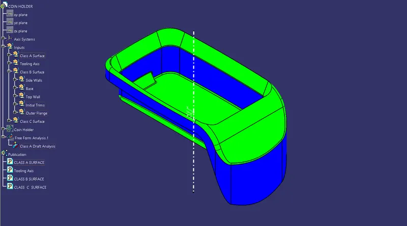
3D VIEWS OF CLASS A SURFACE WITH DRAFT ANALYSIS COLOR CODE
Isometric view
Front View
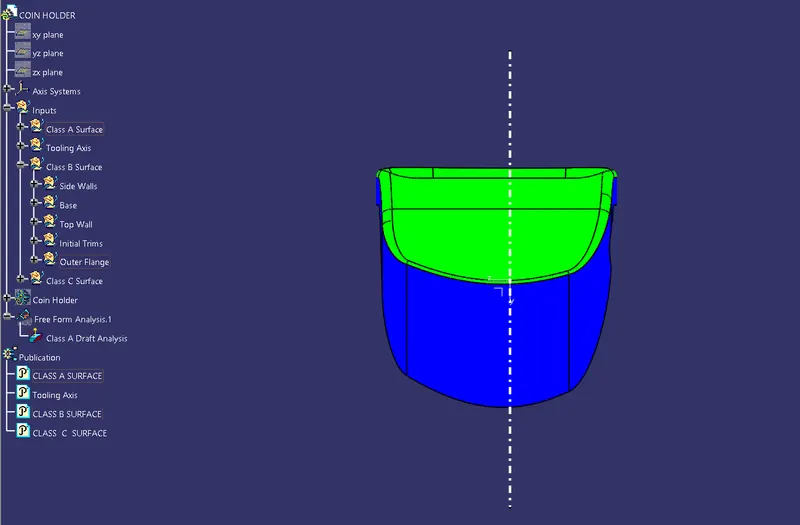
Side View
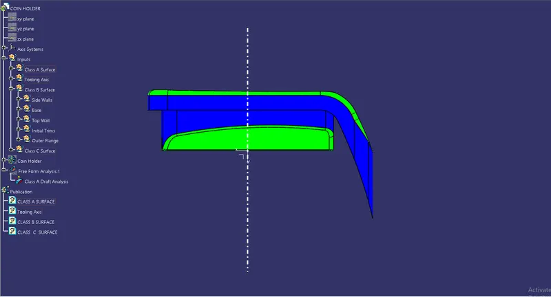
Top View
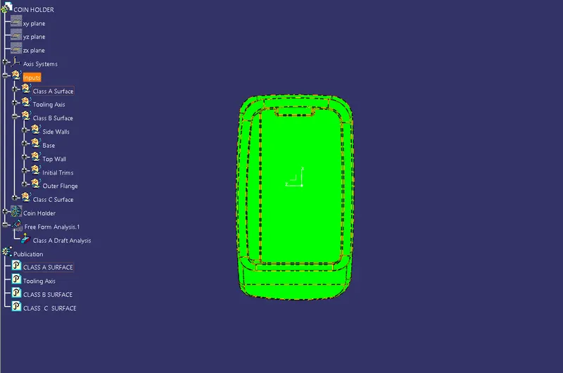
DRAFT ANALYSIS OF SOLID PART
- After creation of tooling axis , draft analysis has been performed.
- Using insert command draft analysis tool has opened.
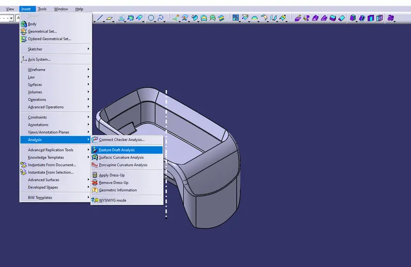
- By clicking on feature draft analysis two pallets opened. One pallet has necessary draft analysis commands and other one is color range which shows the draft values range in form of color.
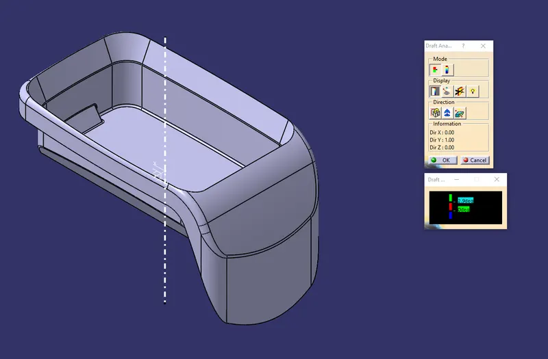
- Inside the draft analysis command window we have selected compass option to create a compass.
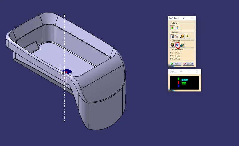
- We have drag the compass onto the component and aligned with the tooling axis and locked using lock command.
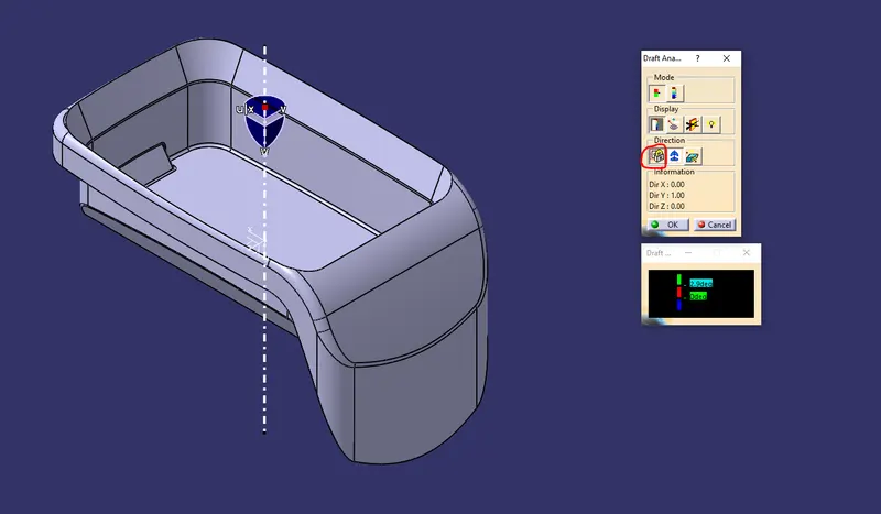
- Now by dragging the mouse pointer anywhere on the component and clicking on it will show us the required draft analysis.
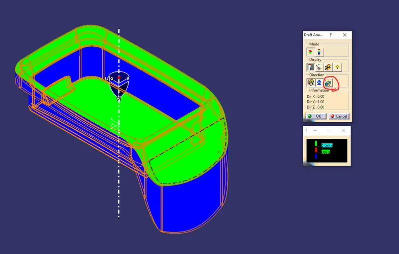
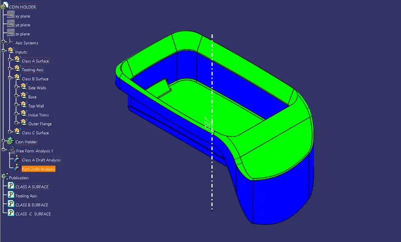
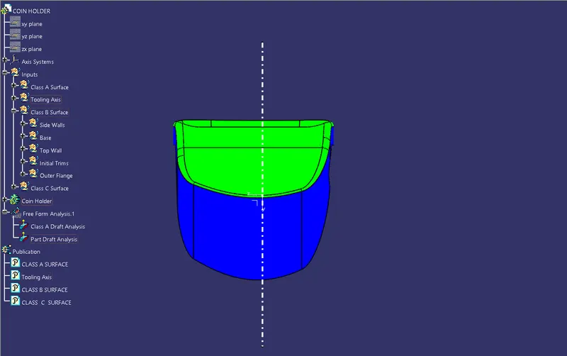
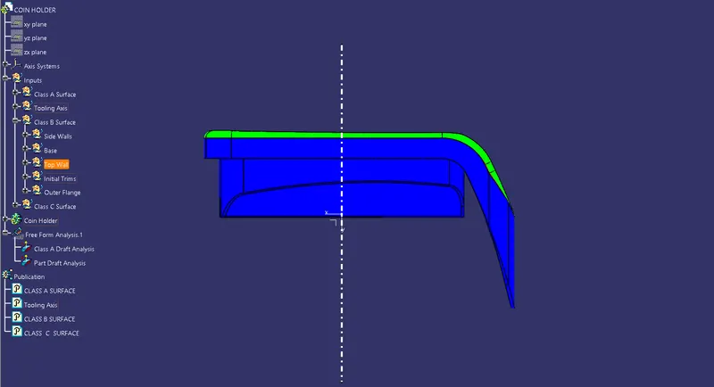
- As per color scale minimum draft angle for all faces should be 2.99 degrees or above that. Inside the color scale green shows draft angle 2.9 or above 2.9 degress. Red shows between 0 and 2.88 degrees. And blue shows negative draft angle. As per the above figure some faces are green and some are blue hence our part has not cleared the draft analysis.
3D VIEWS OF COMPONENT WITH DRAFT ANALYSIS COLOR CODE
Isometric view
Front View
Side View
Top View