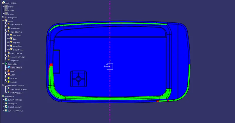
Week 9 - Attachment Feature Creation - Challenge 2
SCREW BOSS DESIGN
1.Thickness of the screw boss should be 0.6 times the thickness of the component
Thickness of the component = 2.5 mm
Screw Boss Thickness = 2.5 x 0.6 = 1.5 mm
Hence Outside Diameter = Inside Diameter + 2 * Screw Boss thickness
As Inside Diameter = 5.2 mm
Outside Diameter = 5.2 + 2*1.5 = 8.2 mm
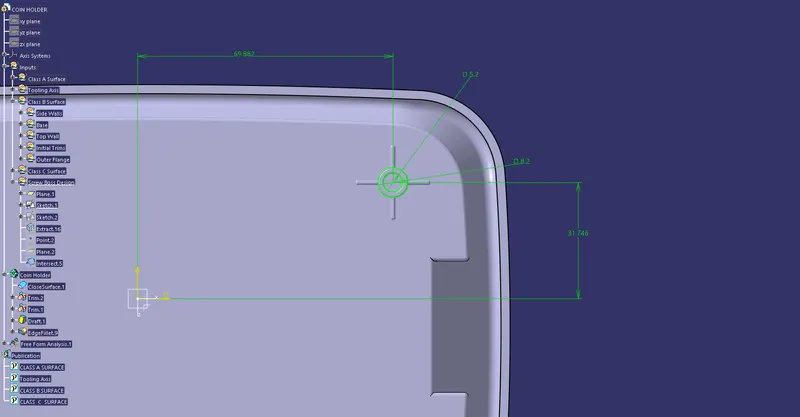
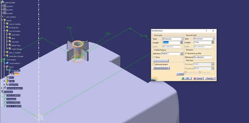
2.Height to Inside Diameter ratio should be less than or equal to 3
Height of the screw boss = 12 mm
Inside Diameter = 5.2 mm
Height to Diameter Ratio = 12/5.2 = 2.3 which is less than 3
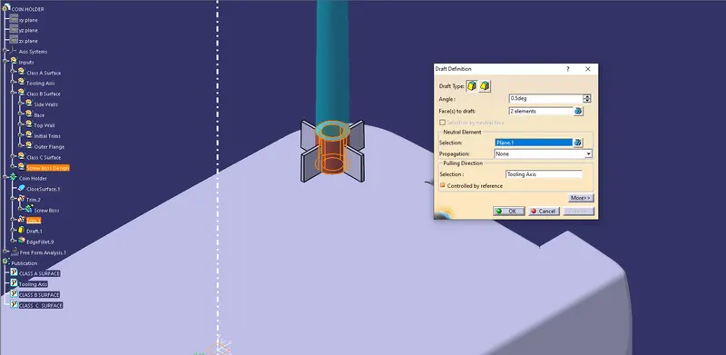
3.Draft should be given as 0.5 degrees to both inner and outer side of the boss
4.Fillet radius for all the edges should be 0.25 mm
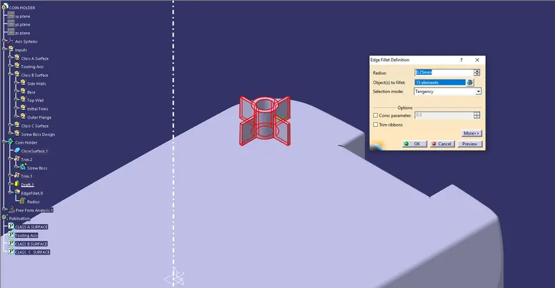
DOG HOUSE DESIGN
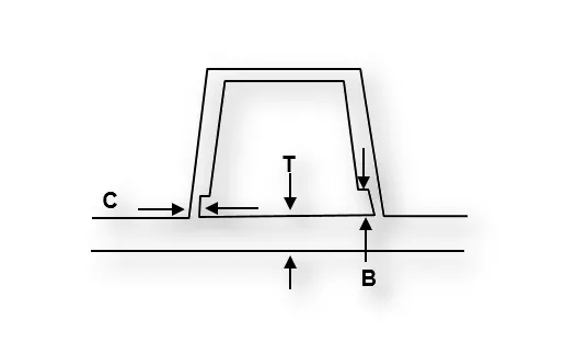
1.Doghouse wall thickness at the intersection of the part wall ( C ) should be 40% or less than the main wall stock ( T ).
Main Wall Thickness - 2.5 mm
Thickness at the intersection of the part wall (c ) = 2.5 *0.4 = 1 mm
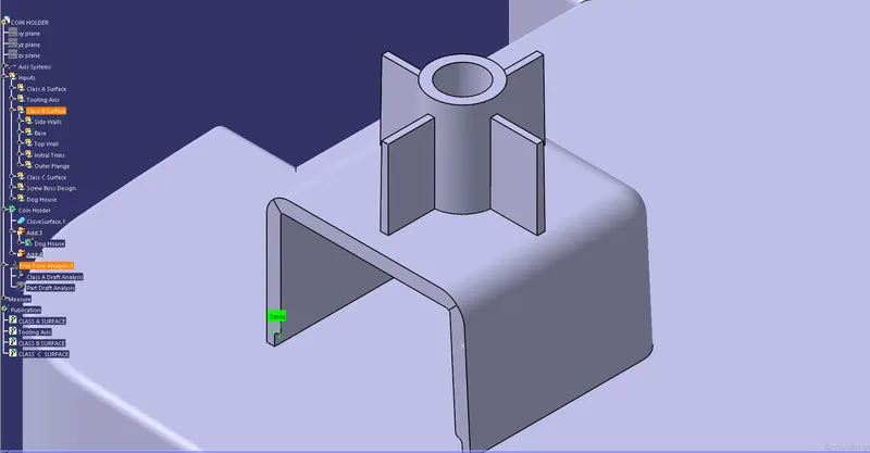
2.Height of ( B ) should be between 3.0 – 6.0 mm
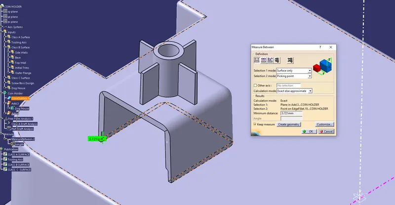
3.Draft Angle should be 0.5 Degrees.
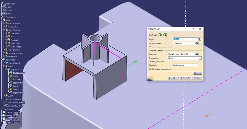
DRAFT ANALYSIS USING MAIN TOOLING AXIS
- Using insert command draft analysis tool has opened.
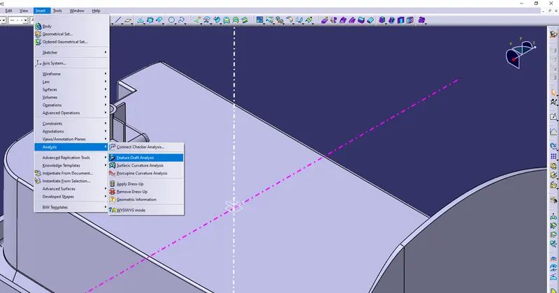
- By clicking on feature draft analysis two pallets opened. One pallet has necessary draft analysis commands and other one is color range which shows the draft values range in form of color.
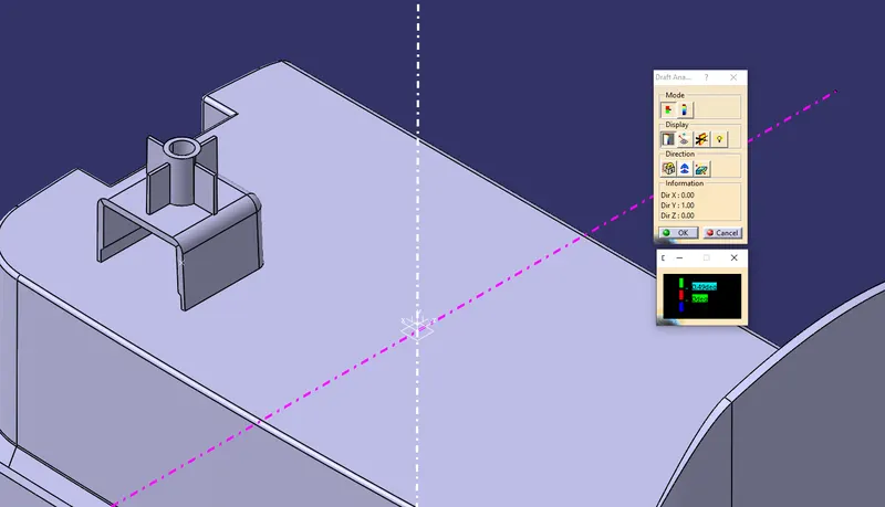
- Inside the draft analysis command window we have selected compass option to create a compass.
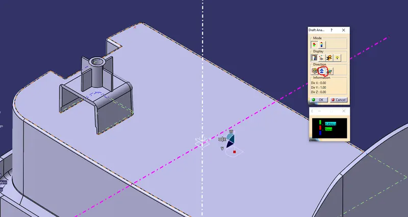
- We have drag the compass onto the component and aligned with the side core tooling axis and locked using lock command.
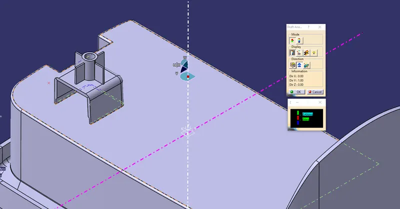
- Now by dragging the mouse pointer anywhere on the component and clicking on it will show us the required draft analysis.
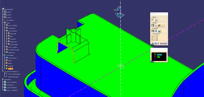
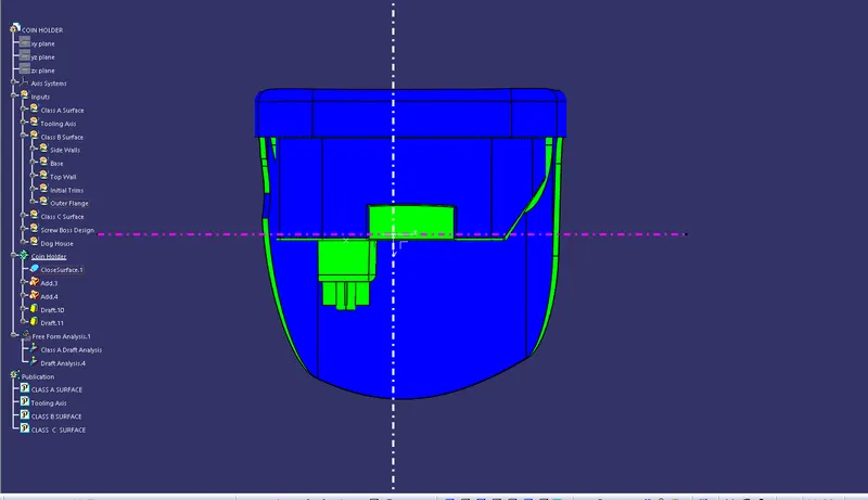
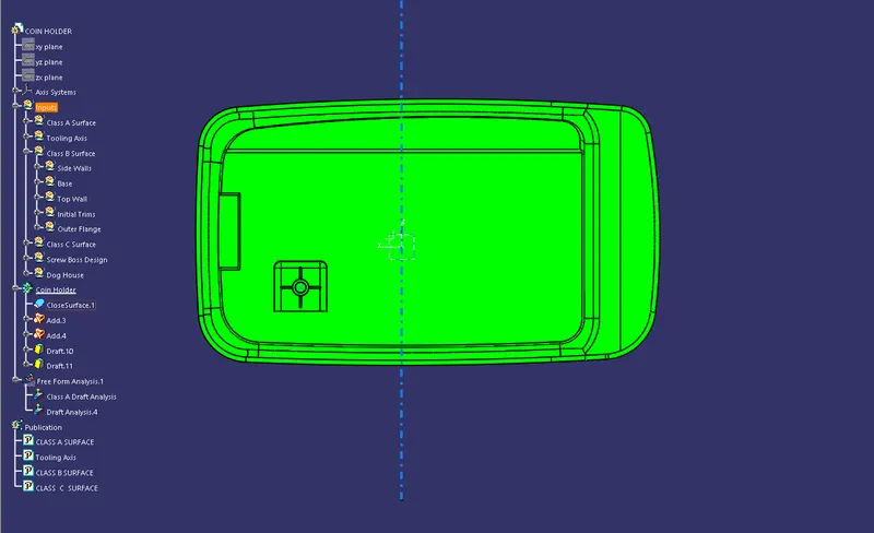
- As per color scale minimum draft angle for all faces should be 0.49 degrees or above that. Inside the color scale green shows draft angle 0.49 or above 0.49 degress. Red shows between 0 and 0.48 degrees. And blue shows negative draft angle. As per the above figure some faces are green and some are blue hence our part has not cleared the draft analysis. Screw Boss is clearing the draft analysis.
3D VIEWS OF COMPONENT WITH DRAFT ANALYSIS COLOR CODE
Isometric view
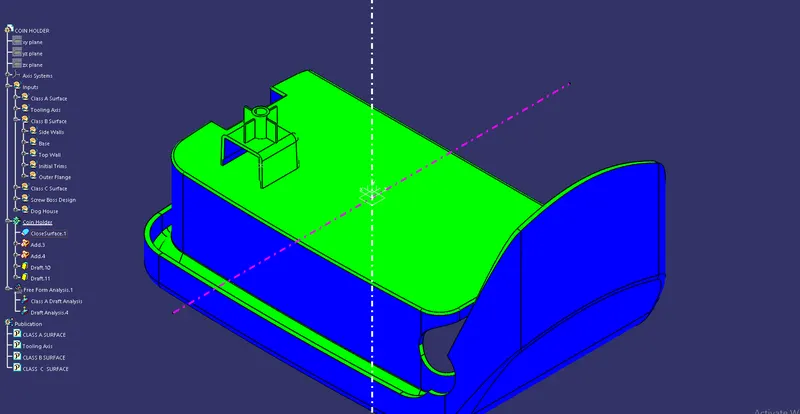
Front View
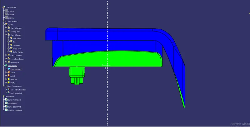
Side View
Top View
DRAFT ANALYSIS USING SIDE CORE TOOLING AXIS
- Using insert command draft analysis tool has opened.
- By clicking on feature draft analysis two pallets opened. One pallet has necessary draft analysis commands and other one is color range which shows the draft values range in form of color.
- Inside the draft analysis command window we have selected compass option to create a compass.
- We have drag the compass onto the component and aligned with the tooling axis and locked using lock command.
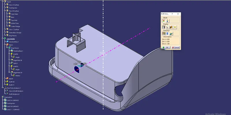
- Now by dragging the mouse pointer anywhere on the component and clicking on it will show us the required draft analysis.
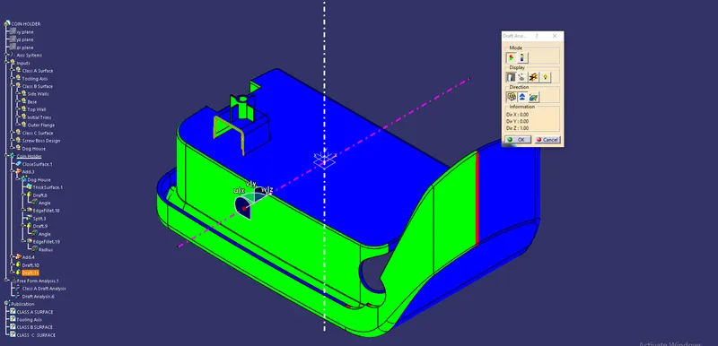
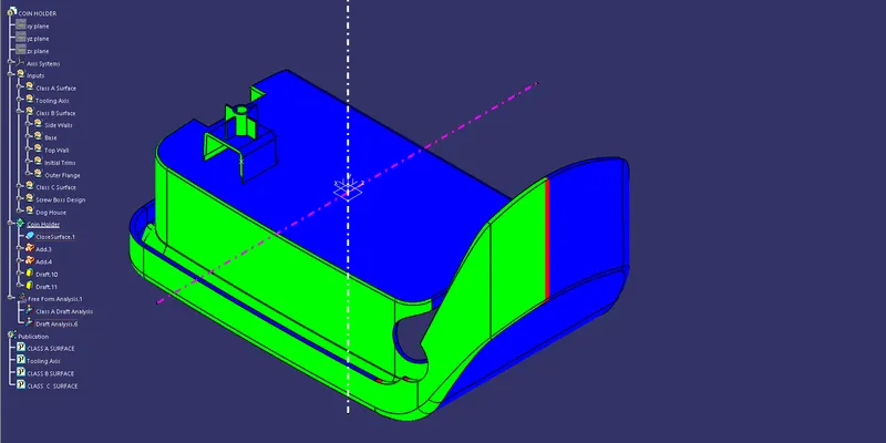
- As per color scale minimum draft angle for all faces should be 0.49 degrees or above that. Inside the color scale green shows draft angle 0.49 or above 0.49 degress. Red shows between 0 and 0.48 degrees. And blue shows negative draft angle. As per the above figure some faces are green and some are blue hence our part has not cleared the draft analysis. Dog House is clearing the draft analysis.
3D VIEWS OF COMPONENT WITH DRAFT ANALYSIS COLOR CODE
Isometric view
Front View
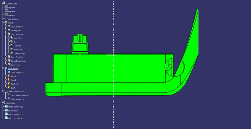
Side View
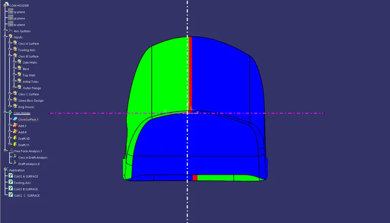
Top View