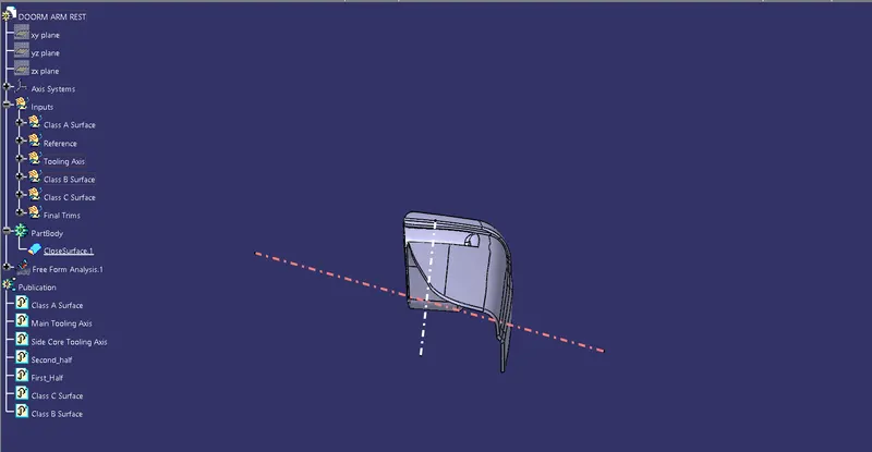
Door Arm Rest Week 8 Challenge
AIM - To design Door Arm rest Using CATIA.
OBJECTIVES
- To create tooling axis following the OEM standard.
- To perform draft analysis on class A surface.
- To create class B surface.
- To create class C surface.
- To create close body.
- To perform draft analysis on close body.
THEORY
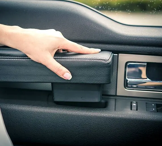
Door arm rests has following applications.
- To provide support to the hands of passenger.
- Window controls are mounted onto the door arm rest.
- Space for cellphones is created onto the door arm rest.
It can have several designs depending upon the requirements of customers.Following image shows one such type of door trim design.
MAIN CONTENT
TOOLING AXIS CREATION
By observing class A surface it can be stated that model will require side core. Hence Part will have Main tooling axis as well as side core.
- Given Class A surface
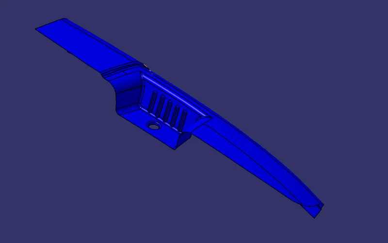
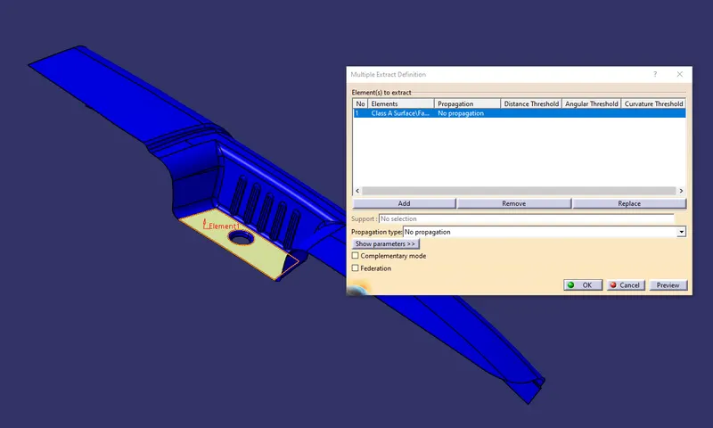
- Lowest surface of the bin has extracted to create reference.
- Point has created on the extracted surface.
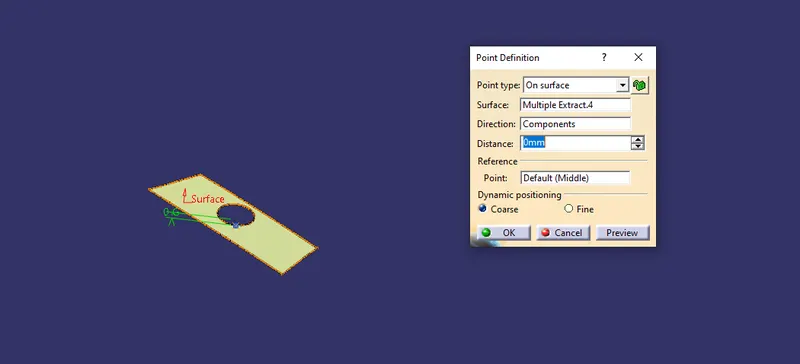
- Using this point Main tooling axis and side core axis has been created.
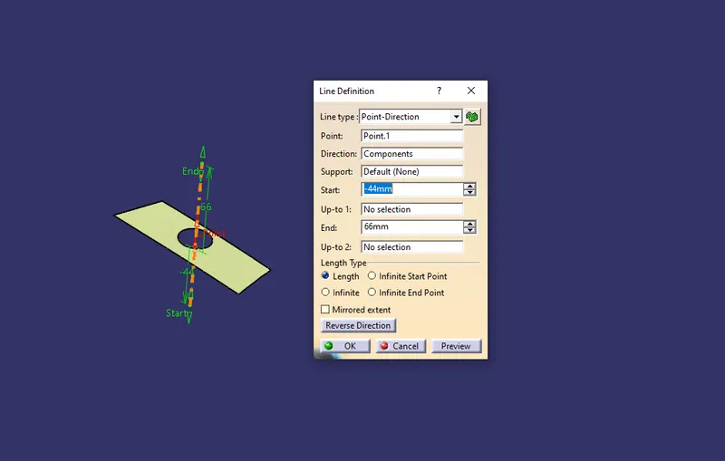
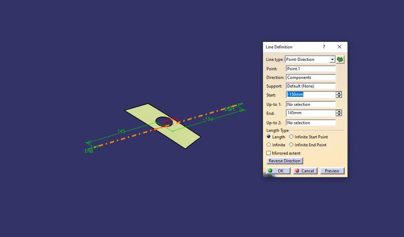
DRAFT ANALYSIS ON CLASS A SURFACE
- After creation of tooling axis , draft analysis has been performed.
- Using insert command draft analysis tool has opened.
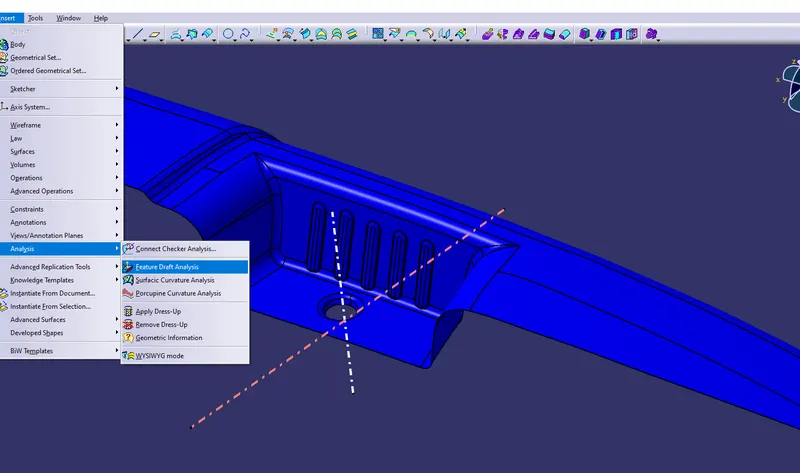
- By clicking on feature draft analysis two pallets opened. One pallet has necessary draft analysis commands and other one is color range which shows the draft values range in form of color.
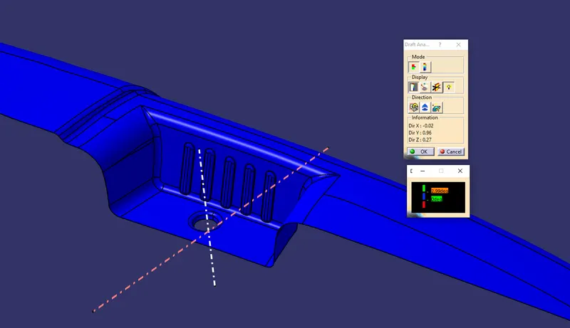
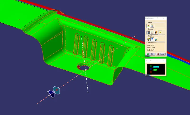
- Inside the draft analysis command window we have selected compass option to create a compass and align with main tooling axis.
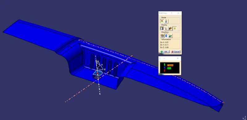
Using Main Tooling Axis
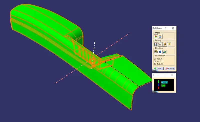
- As per color scale minimum draft angle for all faces should be 2.99 degrees or above that. Inside the color scale green shows draft angle 2.9 or above 2.9 degress. Blue shows between 0 and 2.88 degrees. And Red shows negative draft angle. As per the above figure some faces are green and one small is blue hence our surface has not cleared the draft analysis. We have to contact the class A surface designer to give required draft for faces which are failing.
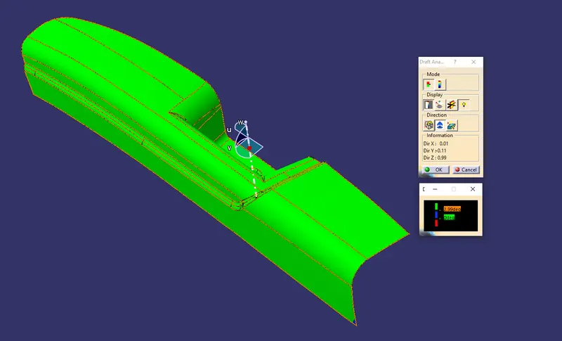
- Bin portion will be analyzed using side core tooling axis.
Minimum draft angle at failing face is 2.641 degrees.
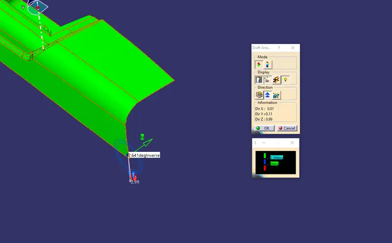
Using Side Core Tooling Axis
- As per color scale minimum draft angle for all faces should be 2.99 degrees or above that. Inside the color scale green shows draft angle 2.9 or above 2.9 degress. Blue shows between 0 and 2.88 degrees. And Red shows negative draft angle. As per the above figure all faces are green hence our surface has cleared the draft analysis.
CLASS B SURFACE
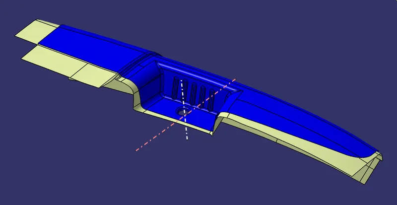
- Using class A Surface we have created the class B surface.
- We have extracted the different portion of class A and offset to the thickness of 2.5 mm and then trimmed together to get a final surface.
CLASS C SURFACE
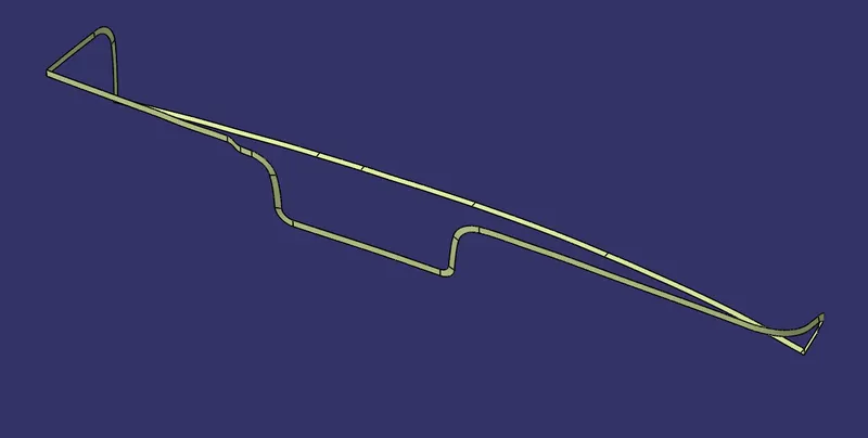
- Using sweep command class c surface is created with a draft of 3 degrees.
CLOSE BODY
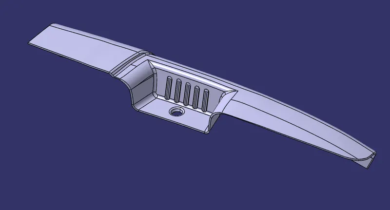
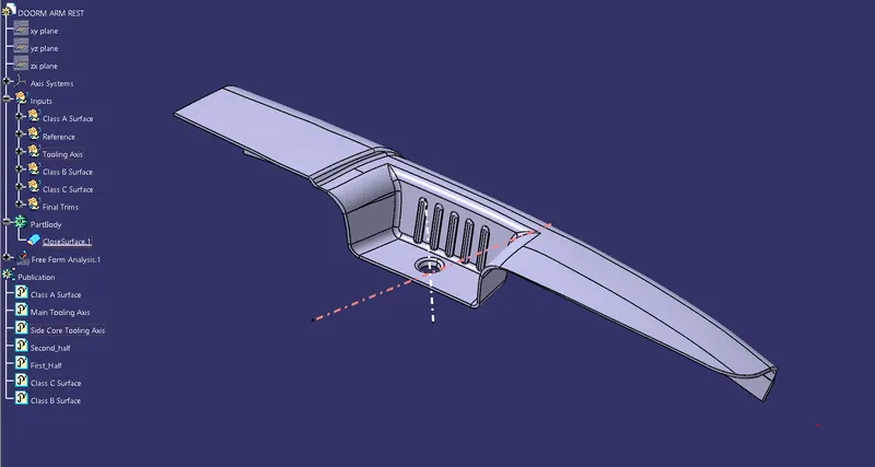
- Using close surface command final body is created.
DRAFT ANALYSIS ON CLOSE BODY
Using Main Tooling Axis
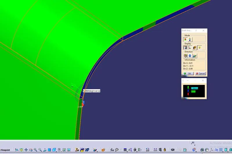
- As per color scale minimum draft angle for all faces should be 2.99 degrees or above that. Inside the color scale green shows draft angle 2.9 or above 2.9 degress. Blue shows between 0 and 2.88 degrees. And Red shows negative draft angle. As per the above figure some faces are green and one small is blue hence our surface has not cleared the draft analysis.
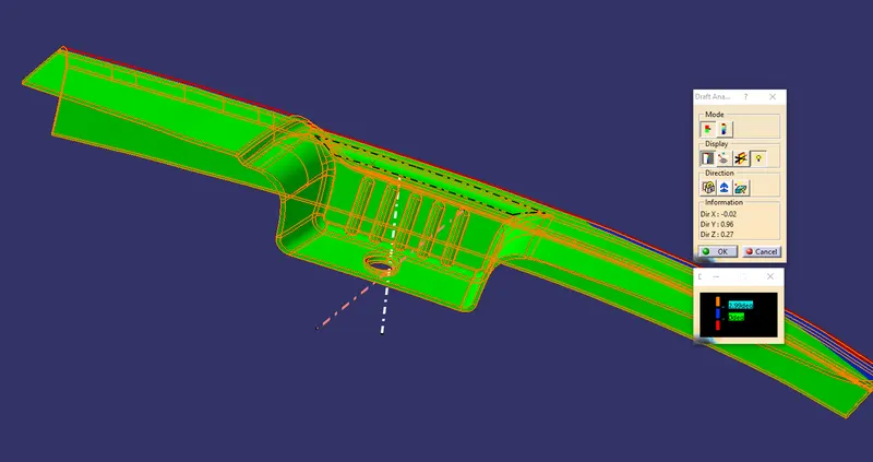
- Bin portion will be analyzed using side core tooling axis.
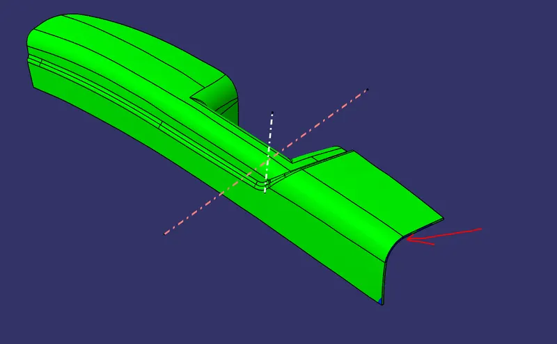
Minimum draft angle at this face is 1.884 Degrees.
Using Side Core Tooling Axis
- As per color scale minimum draft angle for all faces should be 2.99 degrees or above that. Inside the color scale green shows draft angle 2.9 or above 2.9 degress. Blue shows between 0 and 2.88 degrees. And Red shows negative draft angle. As per the above figure all faces are green hence our surface has cleared the draft analysis.
DOOR ARM REST IN DIFFERENT ORIENTATIONS
Isometric View
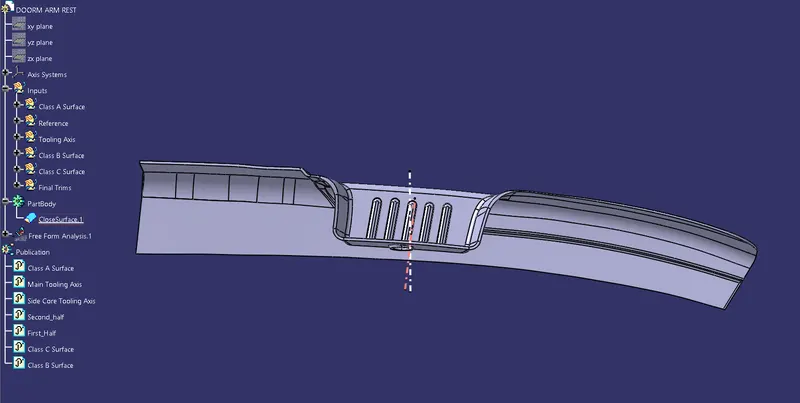
Front View
Top View
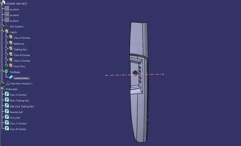
Side View