Week 3 - 2D meshing for sheet metal
OBJECTIVE:
For the given Hood model,
- Create the mid surface for all the components after checking the geometrical errors
- Meshing the mid surface with the given element Quality criteria.
|
S.No |
Quality Criteria |
Value |
|
1 |
Target/Average length |
5 |
|
2 |
Minimum Length |
2 |
|
3 |
Maximum Length |
7 |
|
4 |
Aspect |
3 |
|
5 |
Warpage |
15 |
|
6 |
Skewness |
45 |
|
7 |
Jacobian |
0.7 |
|
8 |
Minimum Quad Angle |
45 |
|
9 |
Maximum Quad Angle |
135 |
|
10 |
Minimum Tria Angle |
30 |
|
11 |
Maximum Tria Angle |
120 |
|
10 |
Tria Percentage |
15 |
- Assigning thickness to the created mesh elements as similar to original component.
PROCEDURE:
Import:
The given file is imported to ANSA using
FIle>Open>File Location>File
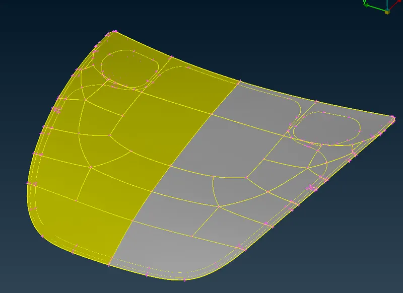
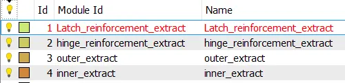
The hood consists of 4 parts:
After the file is imported, inorder to check for any connectivity issues, Topo option under faces tab is selected.
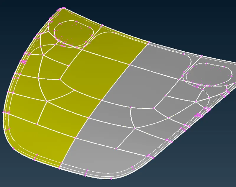
The whole model is selected by pressing shift+left click and drag. Then middle mouse button is pressed to perform topo action.
Orientation:
The model orientation is corrected using the orient option under faces tab which makes the orientation of the whole model same at desired face.
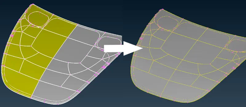
Midsurface:
After the geometry check and orientation of the model is completed, the midsurface of the moel is to be obtained inorder to perform meshing.
To obtain midsurface, offset option under faces tab is used.
To check for the offset distance, the thickness of the each 4 parts should be measured, which can be done using measure option under utilities tab.
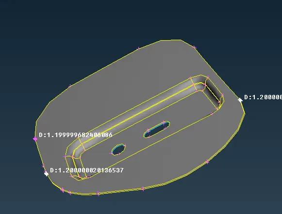
Hinge reinforcement thickness - 1.2mm
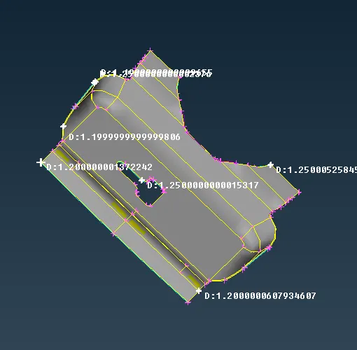
Latch reinforcement thickness - 1.2mm
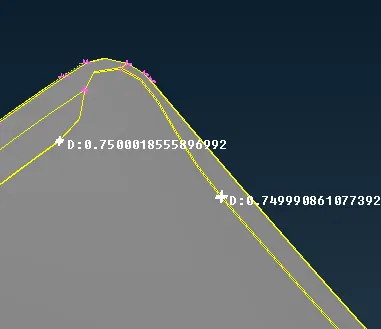
outer extract thickness - 0.75mm
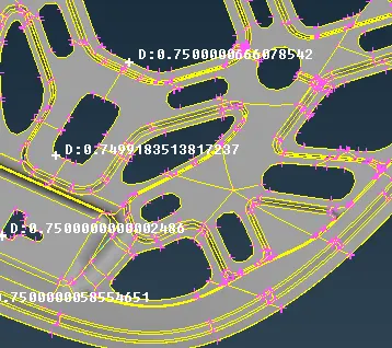
inner extract thickness - 0.75mm
The midsurface of the geometry is created by offseting the surface to half of the thickness.
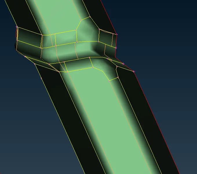
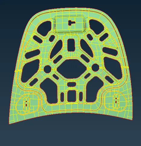
- Created midsurface is further divided into small areas usinng cut tool under macros tab under mesh panel.
- Also unnecessary divisions and sharp corners are avoided using join tool under macros tab under mesh panel.
- For symmetric surfaces, like outer panel and inner extract, only half of the midsurface is generated which can be mirrored later.
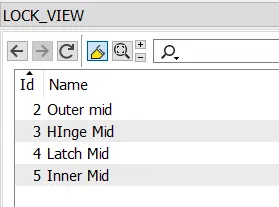
- Each part midsurface is stored under seperate Lock views:
Quality Criteria:
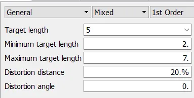
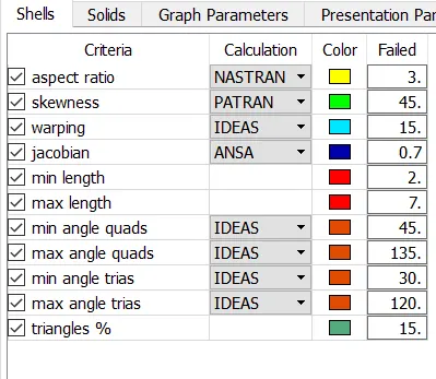
Quality criteria and legth parameters are defined as per given quality index table.
Property:
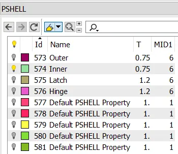
PSHELL property is defined for each part of the hoode model as shown below:
Material:
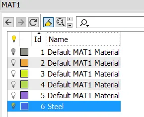
Steel material is defined and the material is assigned to each of the created property:
Meshing:
Meshing is progressed by meshing small divided surfaces one after the other.
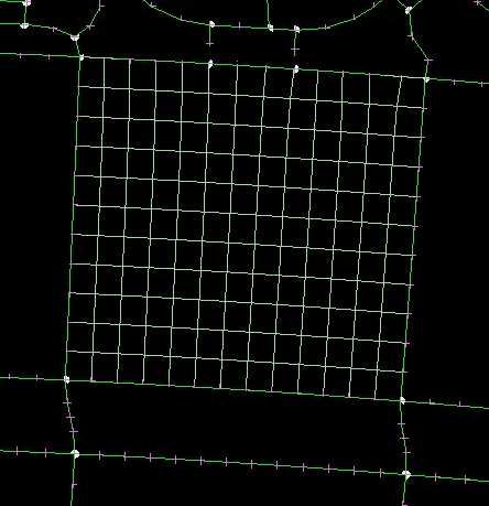
- Meshing of each individual divided area is done using best option under mesh generation tab under mesh panel.
- Meshing is carried out with hidden view mode to ensure that any elements violating the specified quality criteria is eliminated once meshing of each small area of the part is finished.
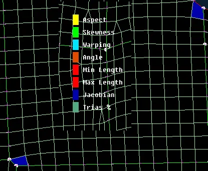
- During meshing, some of the element violated quality criteria, which is cleared using reconstruct option under ShellMesh tab in Mesh panel.
- Tria elements are corrected using Swap and split option under elements tab in Mesh panel.
- Similarly the whole mid surfaces of each part is meshed and any violating elements ar cleared off.
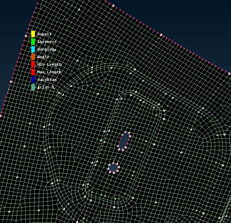
- After the symmetric half of the midsurface is meshed and corrected of defects, the shell elements and surfaces can be reflected using copy option under Transform option in Utilities drop down menu.
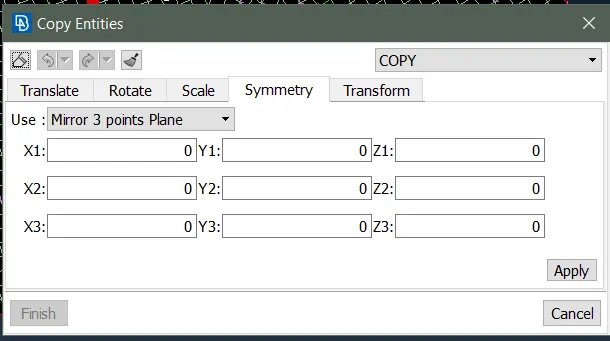
- To mirror the elements, the entities are initially selected and Mirror 3 points plane is selected. Three different points along the middle line of the symetric geometry is selected and applied, which will produce the mirror of the selected entities with selected points as centre.
- While mirroring is done in inner extract which is having the latch reinforcement portion which is meshed seperatley, there is a node disconnectivity, which is cleared using Topo option under faces tab .
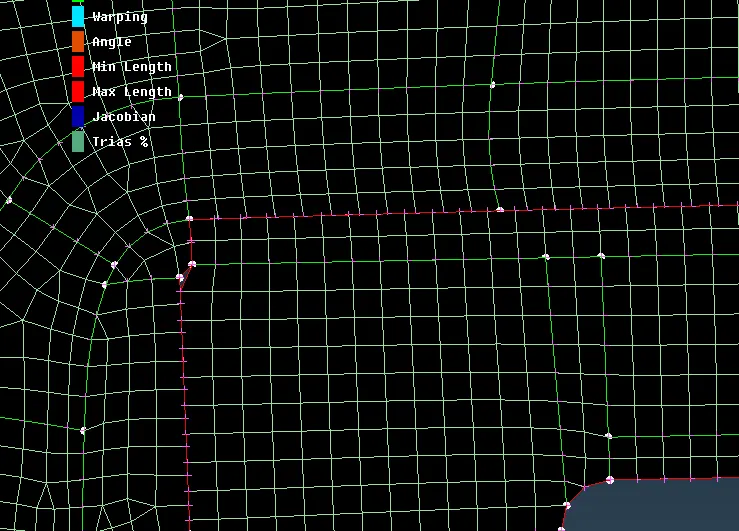
- After topo cleanup is done, connectivity is restored but mesh was erased which is again meshed.
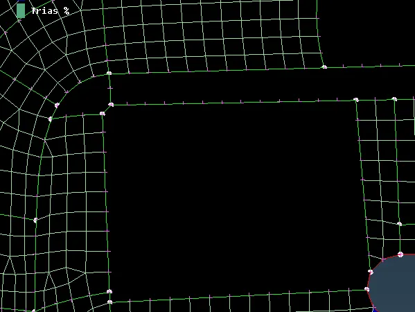
- Hence these surfaces are meshed and the 2-D meshing of the given model is completed.
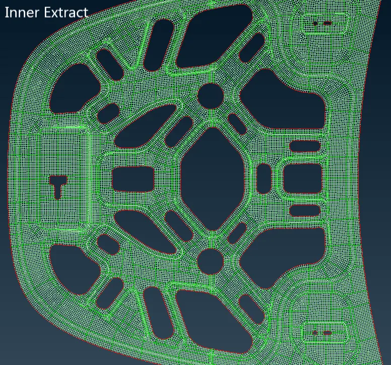
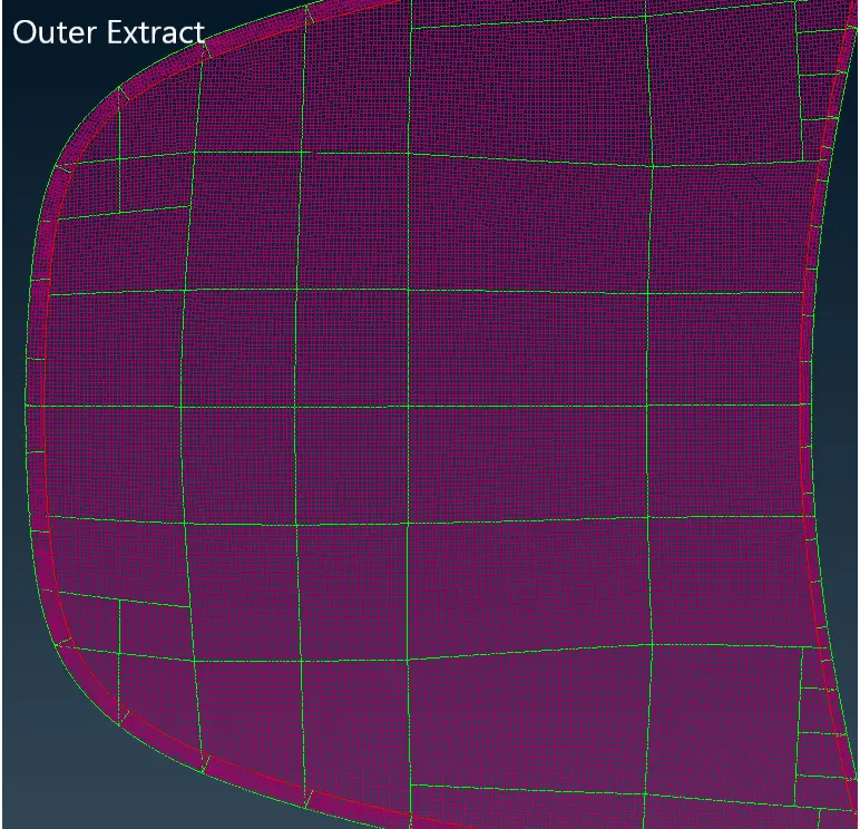
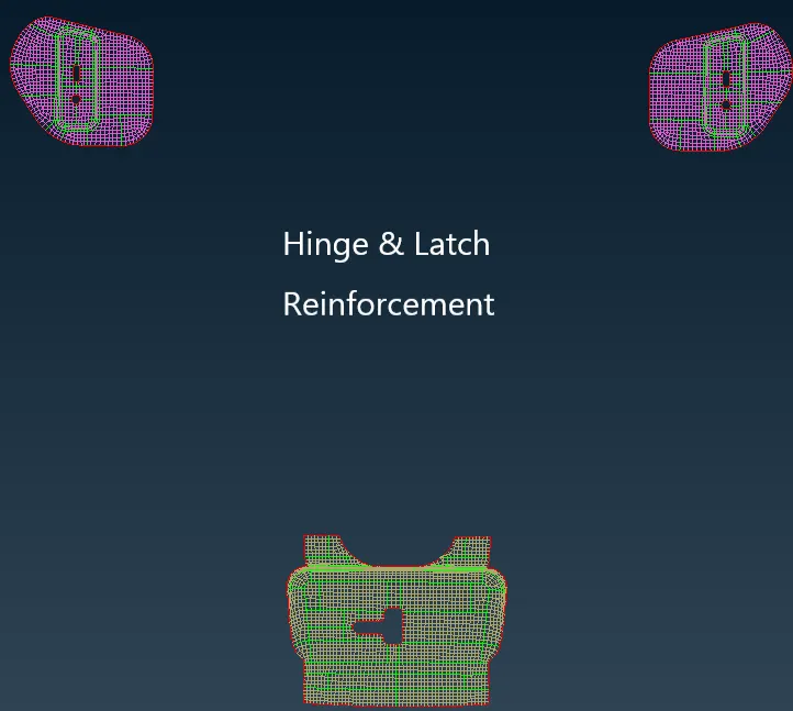
- After each midsurface generated is meshed, it is checked again for Quality Criteria
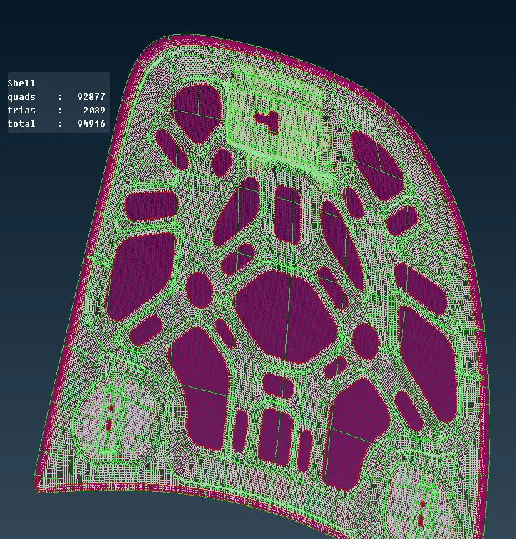
- It can be seen that there are no off elements, which represents that there are no Quality criteria violating elements.
Enabling Thickness:
- Inorder to enable the assigned thickness on the elements, Quality Criteria tab is opened (F11).
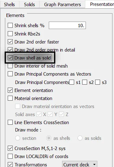
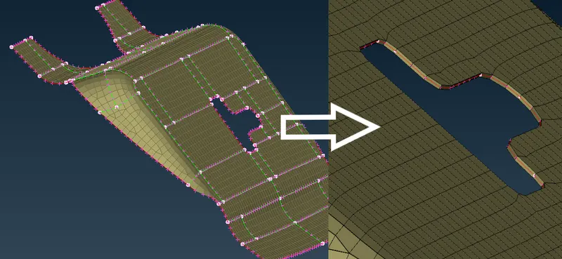
- Under Presentation Parameters, Draw shell as Solid option is checked.
- Once applied, the elements are displayed with specified thickness
CONCLUSION:
- The midsurface of the given hood model was created and seperately stored under Lock view.
- Quality criteria was defined and the midsurface was divided into small areas for better meshing.
- Meshing of the midsurface was performed using best mesh option.
- Elements violating the criteria was cleared and smooth mesh flow was obtained.
- Property was created and applied for each part of the hood and original thickness was defined under each property.
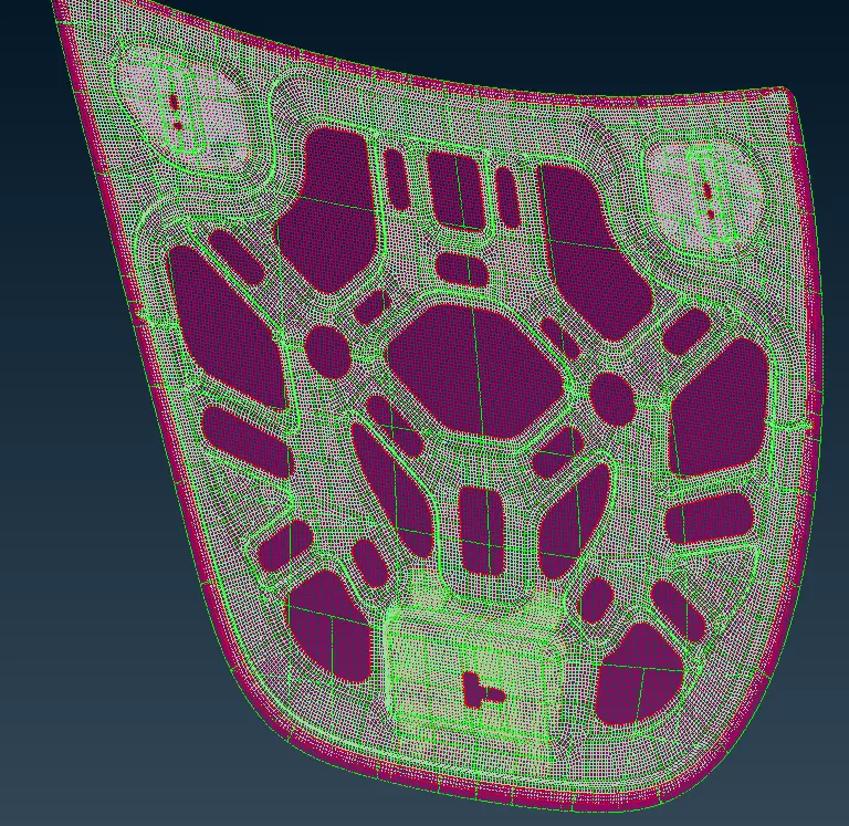
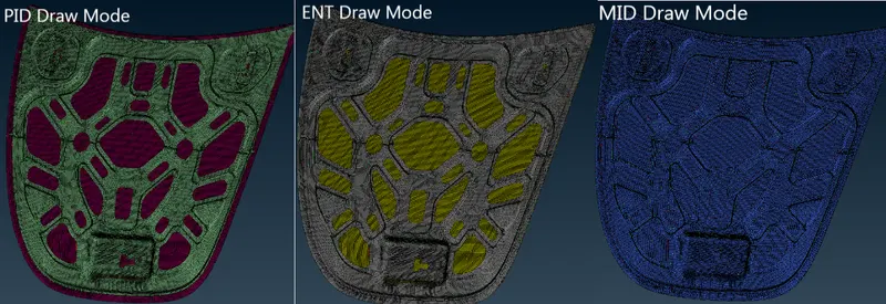
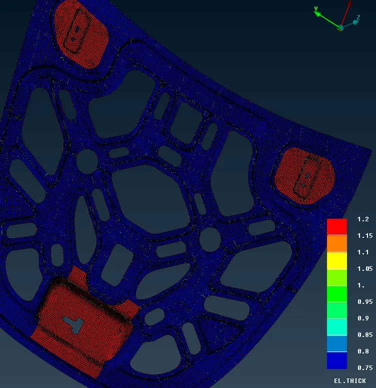
Fringe View to check the element thickness.
Learning Outcomes:
- Whenever ANSA is opened, quality criteria is to be checked and defined properly.
- Macros length parameter should be checked and defined before meshing.
- Geometry stored under locked view should be updated once any changes are made to the geometry.
- Mesh flow can be altered and corrected by using the Num+/- option in some cases.