2D Meshing of Hood Model With HyperWorks
AIM:
2D Meshing of the Hood Model as per following quality criteria.
| Sl.No | Quality Criteria | Value |
| 1 | Target Element Size | 5mm |
| 2 | Aspect Ratio | 5 |
| 3 | Skewness | 45 |
| 4 | Warping | 15 |
| 5 | Taper | 0.5 |
| 6 | Min. Length | 2mm |
| 7 | Max. Length | 8mm |
| 8 | Min angle Quad | 45 |
| 9 | Max angle Quad | 135 |
| 10 | Min angle Tria | 20 |
| 11 | Max angle Tria | 120 |
| 12 | Tria % | 10 |
PROCEDURE:
(1) Import:
Initially the given model is imported using import geometry option
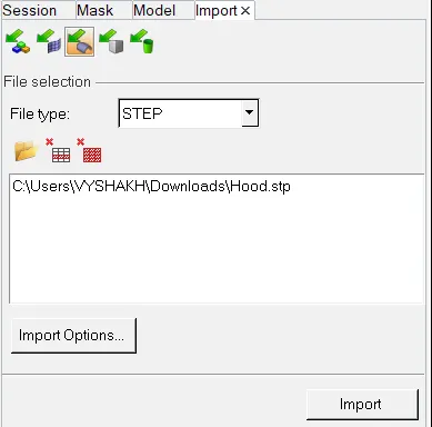
Once the file required is browsed and imported, the model is displayed as follows:
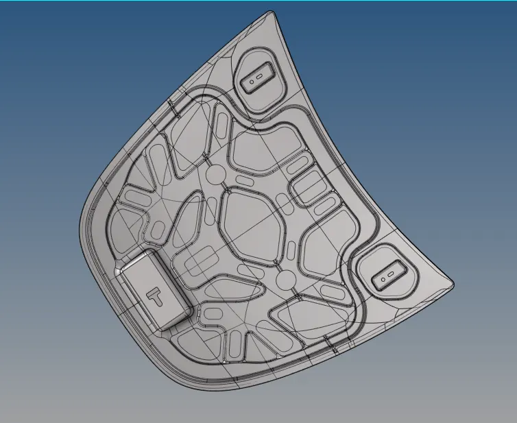
The hood model is developed by using 5 different components as shown below:
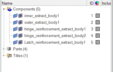
Midsurface extraction,Geometry Cleanup and meshing of each components are done seperately.
(2) Mid-surface Extraction:
- Each component is selected once to extract the midsurface.
- Before creating the mid surface, solids within the component should be deleted by using the delete tool with solids as selection criteria.
- After solids are deleted from the part, mid surface can be generated by using midsurface tool under geometry tab.
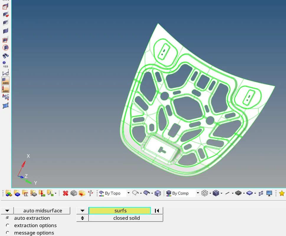
- Once the mid surface is generated, new component named midsurface will be generated in the tab area under model tab along with the other components.
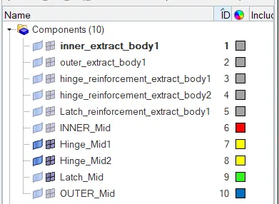
- The new component is renamed according to the hood part under consideration.
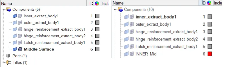
- Similarly midsurfaces of all the components are extracted and saved as different components.
(3) Geometry Clean-up:
- After the mdsurfaces are extracted from the model, before meshing the mid-surface, geometry clean up of the surfaces are done.
- Geometry cleanup is done using autocleanup tool under geometry tab
- Clean-up will remove connectivity errors and restore the surface data to a perfect representation of the part.
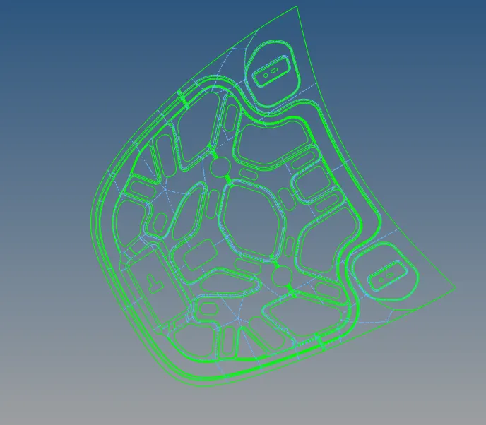
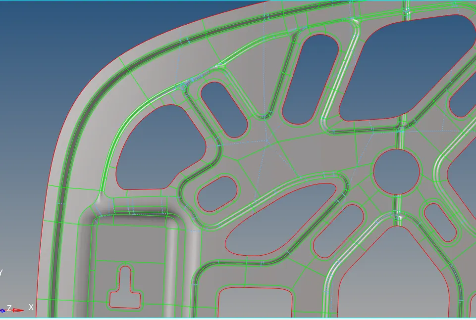
- After geometry cleanup is performed, additional edges as required are created and unwanted edges are toggled using quick edit tools (toggle edge, split surface) under geometry tab.
- Larger surfaces are further divided to smaller surfaces for proper meshing.
(3)Meshing:
- After the cleanup is finished and each component is divided into smaller and simple surfaces to obtain proper mesh.
- The meshing is done by using automesh tool under 2-D tab with elements size as 5 and element type as quad.
- The meshing of each component is done surface wise from one small surface and is progressed into adjacent attached surfaces.
- After each small surfaces are meshed, quality criteria check is carried out inorder to clear any criteria violating elements at early stages itself.
- Criteria check is done using qualityindex tool and check elems tool under 2-D tab.
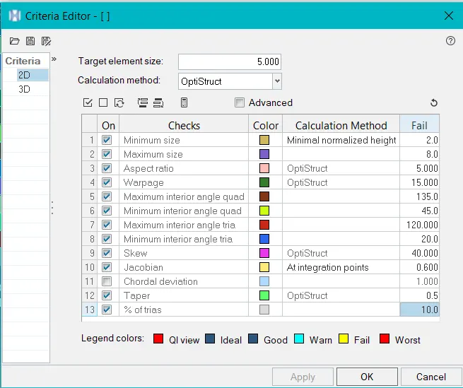
- Under check elems tool, quality criteria is set as follows:
- After criteria is defined, the meshed elements of all components are checked using qualityindex tool.
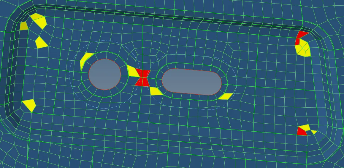
- The elements violating the specified quality criteria are marked yellow and red.
- Cleanup tools like element optimize and place node within the qualityindex is used to optmise the violating elements.
- For elements which are not optimized to within the criteria range with qualityindex tool, elem cleanup tool is used.
- In situations where qualityindex and elem cleanup tools failed to rectify the violating elements, automesh tool is used to remesh the non-optmized elements.
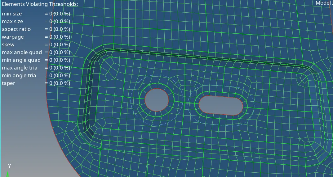
- The elements of the all components are checked if any more violating elements are present.
- If present, the above steps are repeated until all elements fall under the given quality criteria.
(4)Element Checks:
- Edges
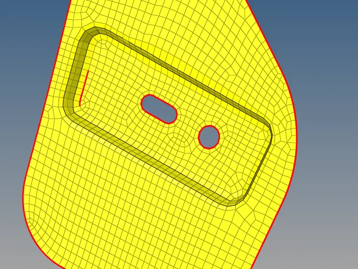
- After meshing of components, at some areas the connectivity between elements where found to be disturbed hence forming free edge within the model which is not desirable.
- Following figure shows a situation where a free edge was formed within the component rather than on the outside edges.
- Inorder to remove these free edges, the edges tool in tool tab is used.
- All the elements of the component are selected and find edge option is selected.
- This finds and creates a free edge component which depicts where all free edges are present.
- If any free edges are formed at undesired areas as shown above, elements near to these edges are selected, preview equivalence option is selected.
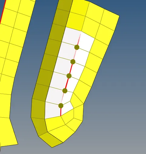
- After preview equivalence option is selected for the selected elements, nodes between the elements that are disconnected causing free edges are displayed.
- Then equivalence option is selected with desired tolerance value which will connect the nodes between disconnected elements.
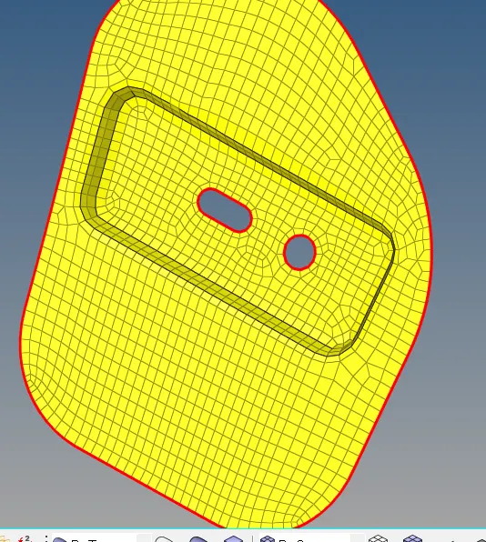
- After equivalence is done, again find edges tool is used by selecting all the elements.
- The same process is carried out for all the components to remove any undesired free edges or element disconnectivities.
- Element Normal:
- Normal tool from the Tool tab is used to review the direction of normal of all the elements of the component.
- The normal of all the elements should act in the same direction.
- For elements which are not in the same direction, these elements are selected and reverse option is used under the normal tool tab.
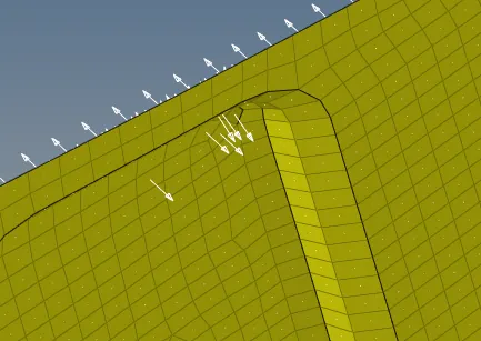
- Each component is checked for normal and if variation is found, the same is corrected.
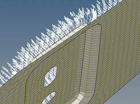
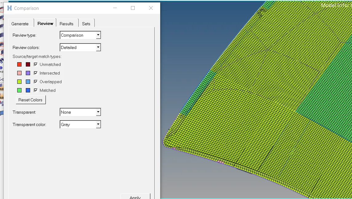
- Comparison - elements to surface
- Comparison tool is used to check the connectivity of elements to the surface of the components.
- Initially the elements in the component is selected, then the surface to review connectivity is selected and comparison test is run.
- If any unmatched elements are observed (red), then the project tool under tool tab is used to project the unmatched elements to the desired surfaces.
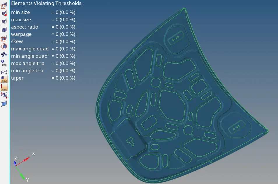
- Finally after elements of all components are checked, all elements are selected and qualityindex tool is used to ensure there are no criteria violating elements.
(5)Assigning Thickness:
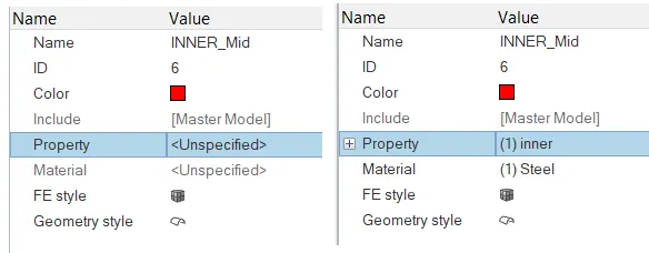
- Initially Material and property for each component is created under the tab area.
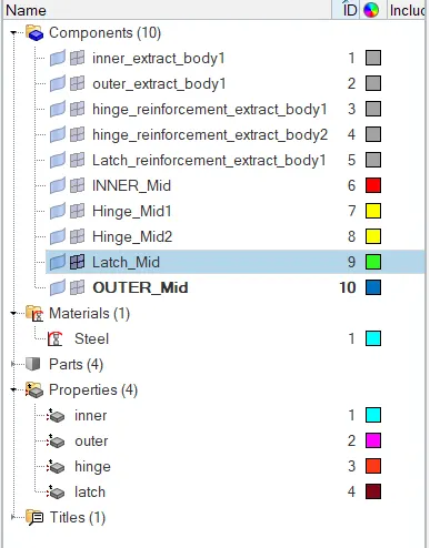
- Property and Material is renamed as desired.
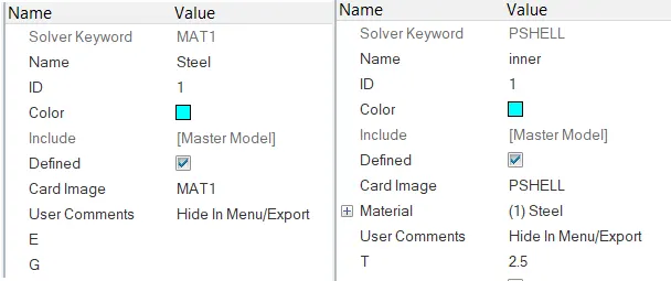
- Card image for material selected is MAT1 and for property is PSHELL for all the components.
- A thickness of 2.5 is also assigned under the property.
- After property and material is created and defined as desired, this property is assigned to each of the component created.
CONCLUSION:
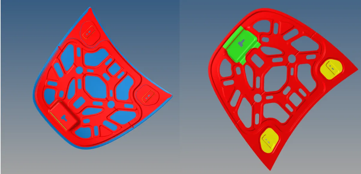
- Mid-Surface is extracted for each component seperately and meshing of the hood model is performed with elements having quality criteria within the given range.
- Different properties for each component is assigned and thickness is also assigned for the elements.