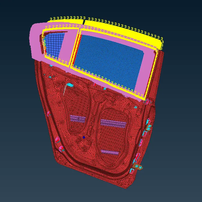
Week 6 - Creating connection for Rear door
OBJECTIVE:
for the given Rear door FE model,
- Create and Apply different PIDs for different components.
- Perform suitable connections
PROCEDURE:
IMPORT:
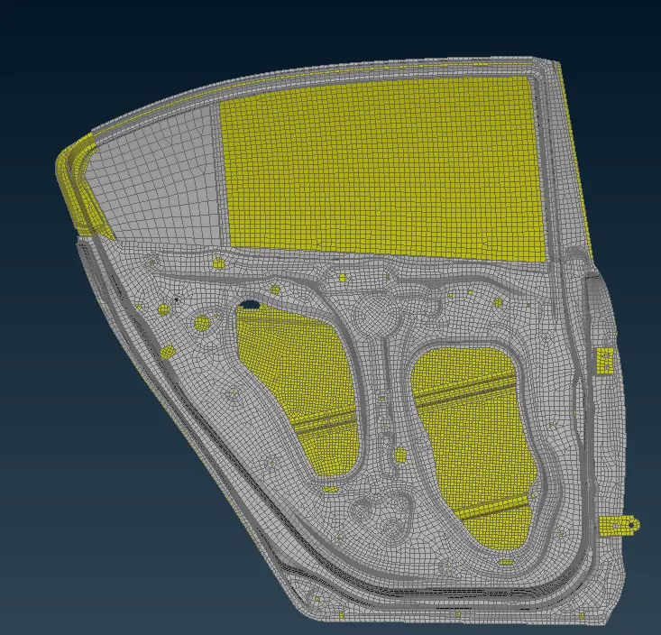
- The given file is imported using open > File location >File
- The file is shown as below:
CREATING PID:
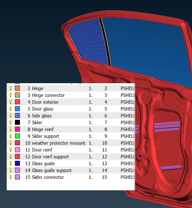
- Door being a system consists of many sub-systems. But the model is only stored under a single PID, which is seperated into different PID's as shown below.
BOLT Connections:
- Once different PID are created, the areas where a bolt connection is suitable is found and bolt connection is made.
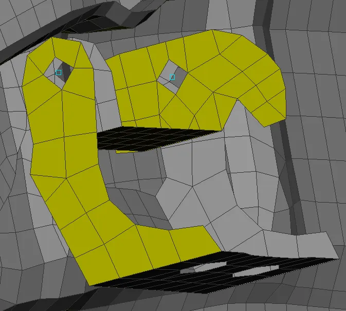
- Starting from the hinges part where door is fixed to the car body.
- Centre point is created where bolt is to be fixed using on COG option under points tab under TOPO panel.
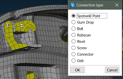
- COG point is converted to bolt with convert tool.
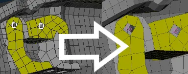
- Once it is converted, it is realized into a proper bolt connection with help of connection manager.
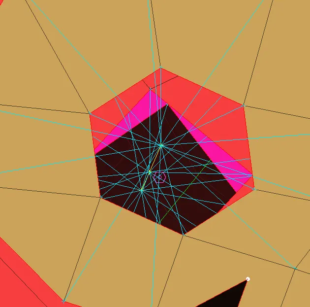
- Some bolt connections are also made manually using RBE2 option (multi nodes) under NASTRAN Panel and bolt connection is established
- Hence bolt connection at suitable locations are made.
SPOT WELD Connection:
- Areas where different parts are connected uding spot weld method is found out.
- COG point is made on one part. It is then converted to spotweld point using convert option.
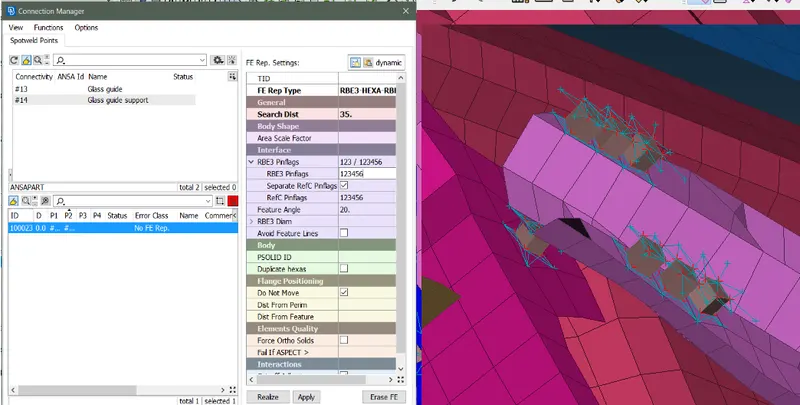
- Then the spot weld point is realized by using the connection manager.
- PSOLID is created inorder to store the spotweld ID.
- Search distance, RBE3 Pinflag and PSOLID ID is entered as desired to obtain the spotweld
DOOR HANDLE:
- The open part at the handle location is conected using RBE2 optiion (multinodes) under NASTRAN panel.
- The master nodes of the two RBE2 lonks are connected using a 2 node RBE2 link.
- At the master node of the 2 node link, mass of 250g (0.00025 Tonne)is introduced by using CONIMI option (CONM2 - nodes)
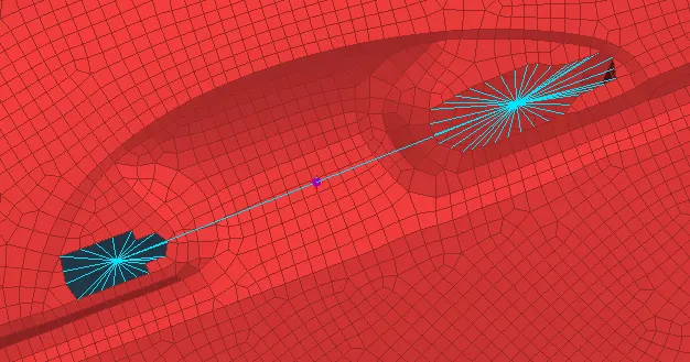
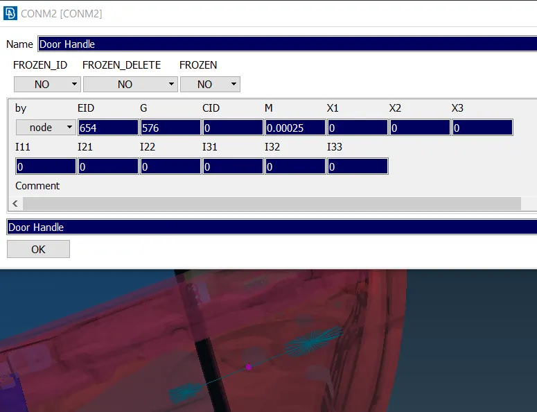
- Hence the door handdle part is connected with RBE2 lonks and added mass.
- BUSH Connection for window weather protection.
- Inorder to create CBUSH links, initially a curve across the ends of the mirror is created using FE2Curve option under perimetes tab.
- Curve is then converted into seamlines using the convert tool.
- A copy of this line is transformed to the inner side of the door to obtain CBUSH links from both sides of the window.
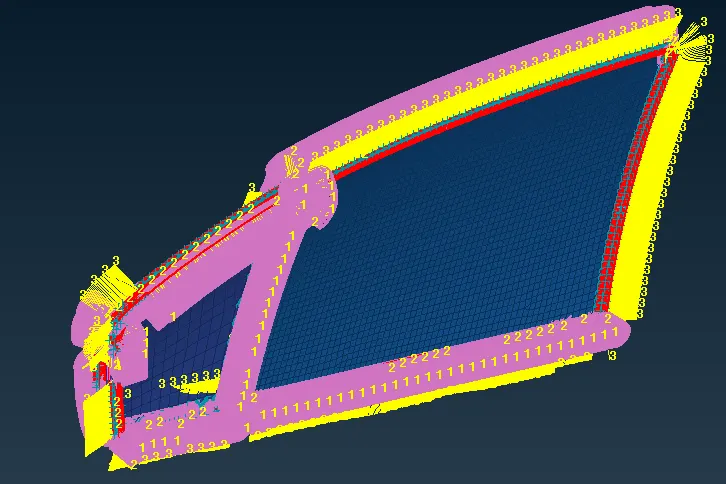
- Using connection manager, this seamlines are realized into CBUSH links.
- Once all the CBUSH elements are created around the window glass, it is to be aligned to the global axis
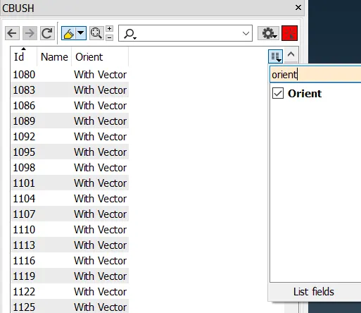
- All the CBUSH links are selected and modify option is selected.
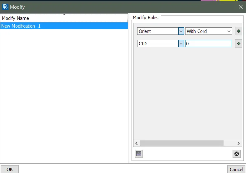
- Modification is performed as shown above. CID defines the cordinates, which defined as 0 gives the global cordinates.
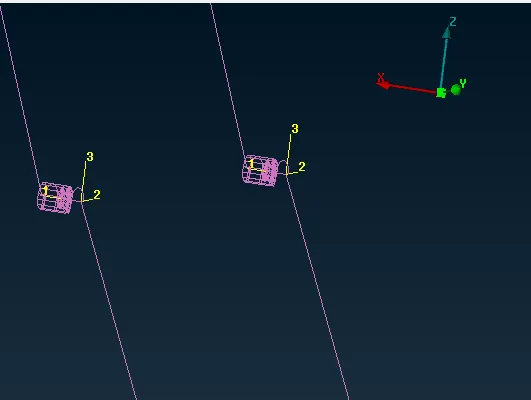
- After orientation is performed, the CBUSH links are aligned in the global axis.
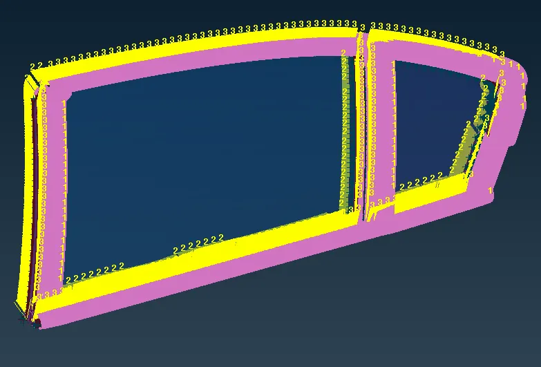
- CBUSH links are created to act as weather strips placed along the window glass as shown above.
CONCLUSION:
Given model was performed with the follwoing actions:
- BOLT connections made at desired areas.
- SPOT weld connections made at required areas
- CBUSH connections made to replicate weather strips along the edges of the windows.