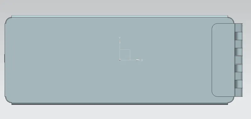
Advanced Sheet Metal Design Using NX Cad Challenge_2_Box Assembly
Designing Box Assembly with NX Sheet Metal Application
OBJECTIVE:
To create a Box Assembly by using NX Sheet Metal Application.
Introduction:
This work provides a step by step detail in creating the BOX-Assembly.
Design Methodology:
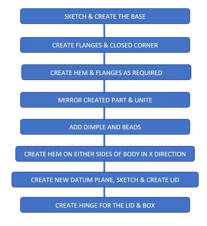
PROCEDURE:
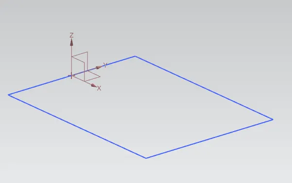
1) Sketch rectangle with given dimensions.
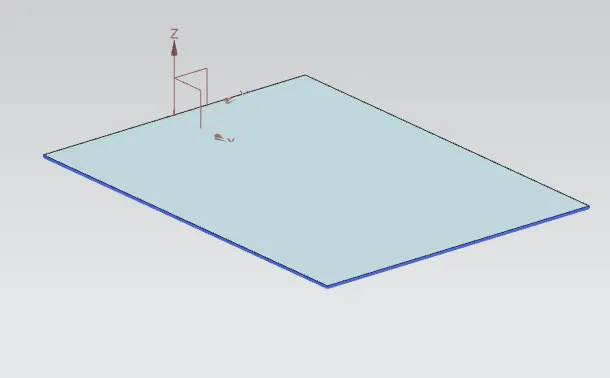
2) Create the base using the tab option
3) Create the flanges on both sides of the base ssurface using Flange option:
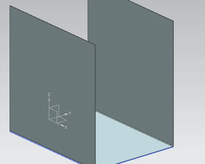
4) From the created flange, create another flange on the sides of the surface forming a box shape.
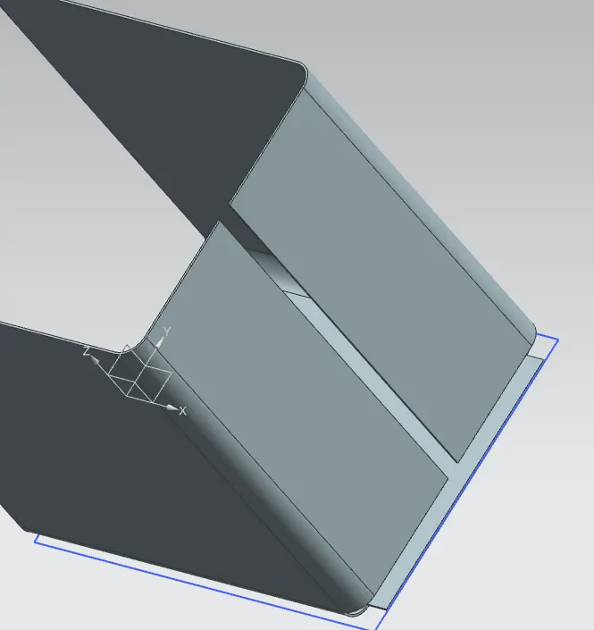
5) Once flanges are created, Closed Corner option is used to close any gaps between the flanges and the base surface.
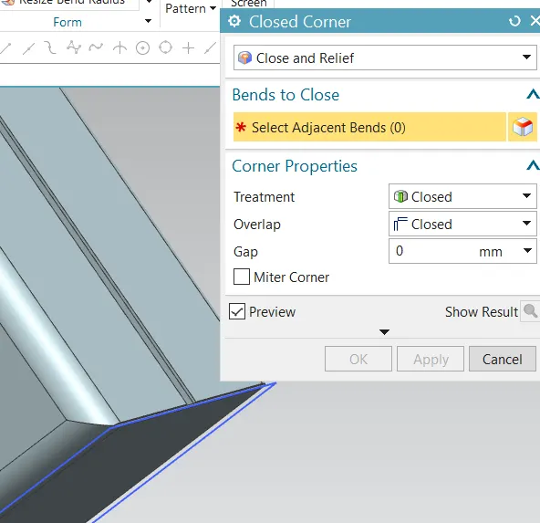
6) Flanges are created at areas where open type hem flanges are to be created:
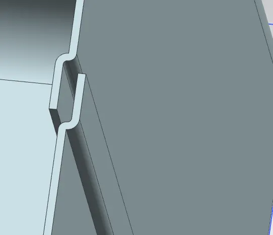
7) Hem flanges are created to form a closed connection:
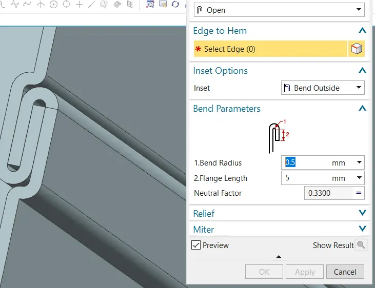
8) To obtain the complete Box body, Mirror Body option is used:
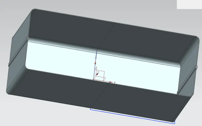
9) once mirrored,Unite option is used to join both the parts to a single connected box body.
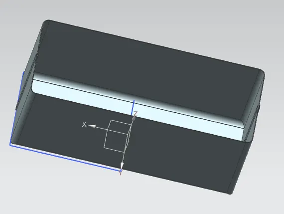
10) Unbend option is used and Sketch option is used to obtain the dimple profile.
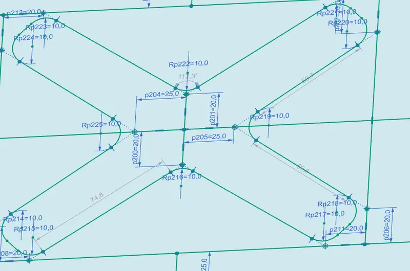
11) Similary Dimple and Beads as specified is also created:
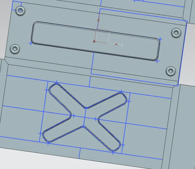
12) Hem flange of type closed on the inner box body is created
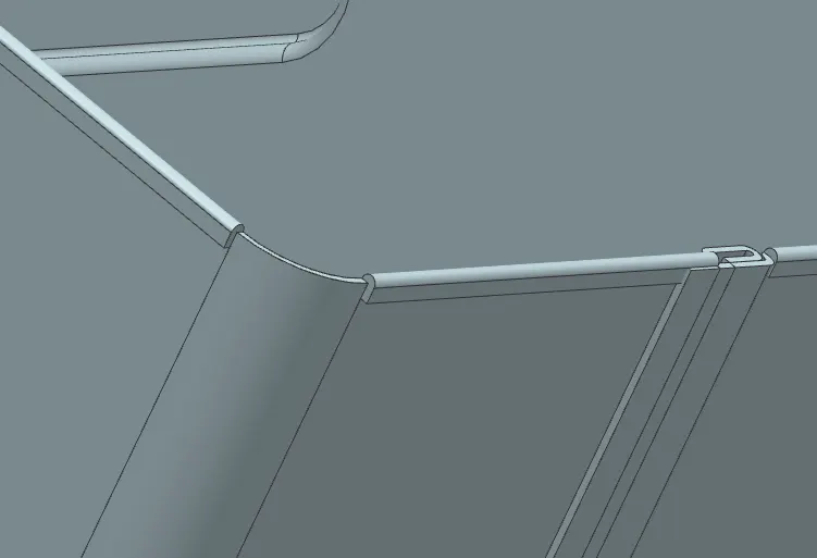
13) New Datum Plane is created at a distance inorder to create the lid to the box body.
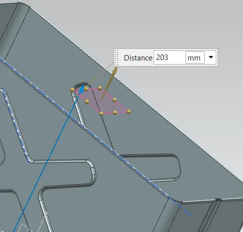
14) Sketch is made on the new datum plane with box body as reference to create the Lid:
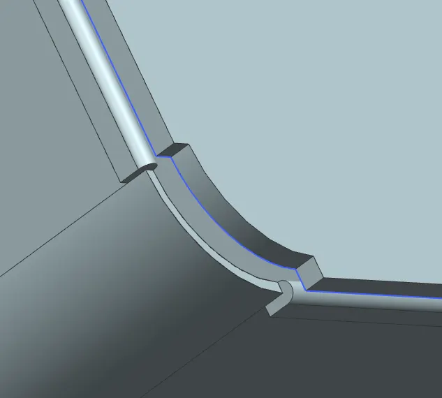
15) Flange for lid is created using flanges option:
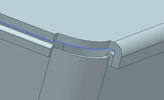
16) New sketch is created on side flange of box body and Flange option is used to create hinge body.
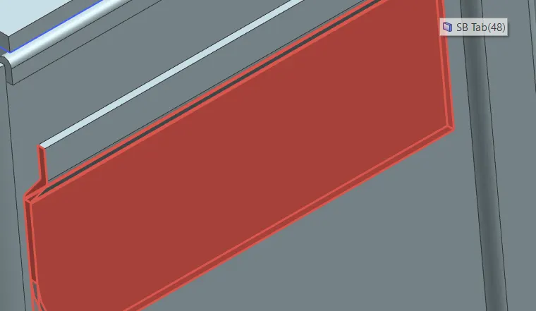
17) From the created flange, Open loop hem flange is created to represent the hinge fixed on the box body.
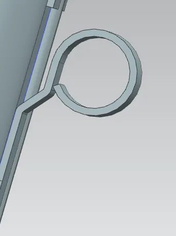
18) The created hem flange is Unbend to create the cutout:
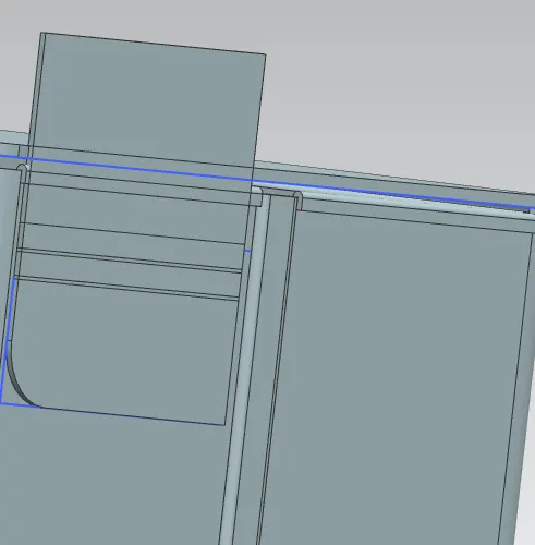
19) Sketch of the section to be cut out is made by selecting the hinge face as the plane:
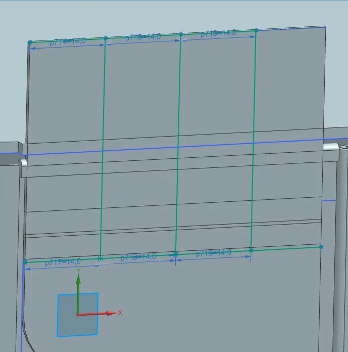
20) Normal Cutout option is used and required sections are deleted.
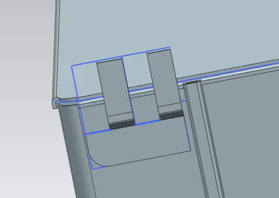
21) Atfter cutout is made, the part is Rebend to obtain the required hinge profile.
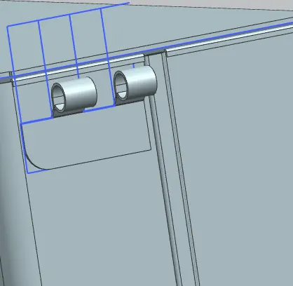
22) Similarly base and flange on lid part is also created for the hinge and similarly unbend to perform cutout action:
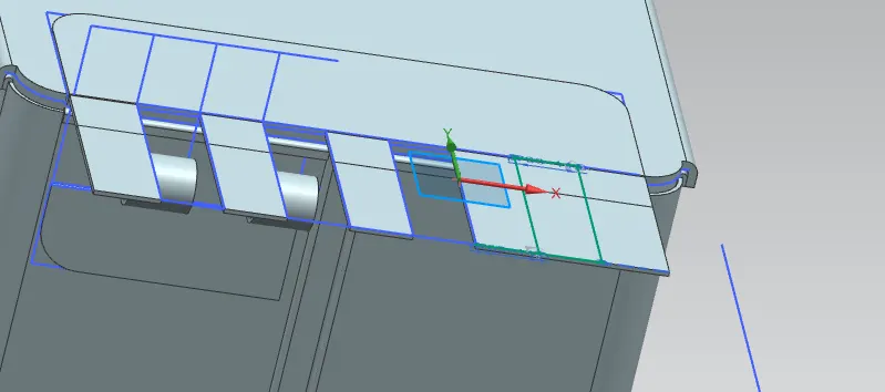
23) After the hinge cutout on the lid part is finished, rebend option is used to obtain the hinge.
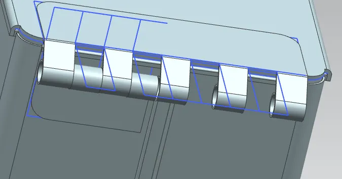
24) THe hinge on the box body is mirrored using the Mirror Body option.
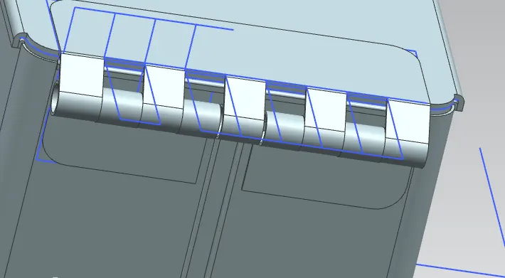
Hence the required Box-Assembly is created by following the above steps.
CONCLUSION:
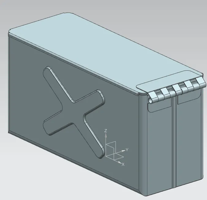
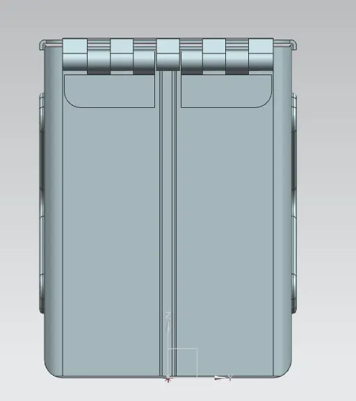
The Box Assembly is created and seperate views of the same are given below:
Isometric View:
Back View:
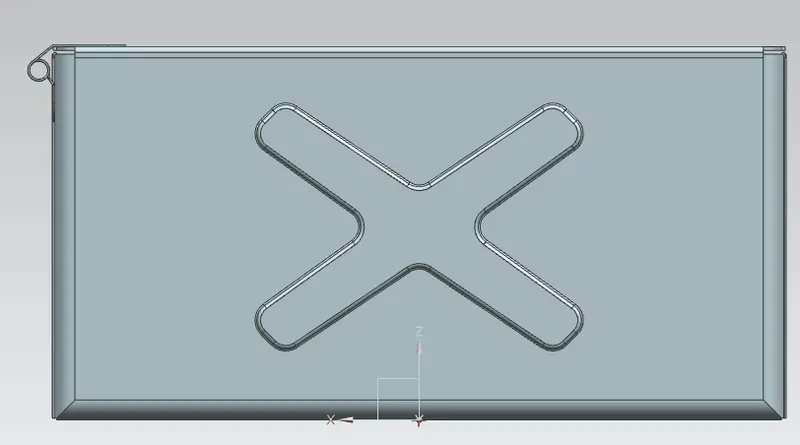
Right side view:
Top view: