Week 12:Project 2-Meshing of Rear Wheel Holder challenge
AIM:
- Extract Mid-surfcae of the components in given Rear wheel Holder Model.
- Perform Geometry cleanup of midsurfaces obtained
- Perform Meshing on the components as per following Quality Criteria:
Target Element Length = 5 Units
| S.N | Quality Criteria | Value |
| 1 | Aspect Ratio | 5 |
| 2 | Skewness | 45 |
| 3 | Warping | 15 |
| 4 | Taper | 0.5 |
| 5 | Min. Length | 2 Units |
| 6 | Max. Length | 8 Units |
| 7 | Min angle Quad | 45 |
| 8 | Max angle Quad | 135 |
| 9 | Min angle Tria | 20 |
| 10 | Max angle Tria | 120 |
| 10 | Tria % | 10 |
PROCEDURE:
Import:
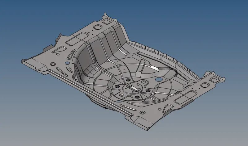
- Given model is imported to Hyperworks using import Model option.
- The model is displayed as follows:
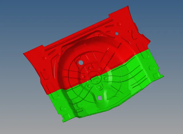
- Model is further divided into 2 components with help of trim with surf/planes option under surface edit tool.
- Midsurface extraction,Geometry Cleanup and meshing of each components are done seperately.
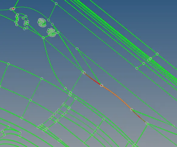
- While model is imported some edgees are not created properly which is corrected using toggle edge option.
Mid-Surface:
- Each component is selected once to extract the midsurface.
- Before creating the mid surface,if any solids within the component should be deleted by using the delete tool with solids as selection criteria.
- After solids are deleted from the part, mid surface can be generated by using midsurface tool under geometry tab.
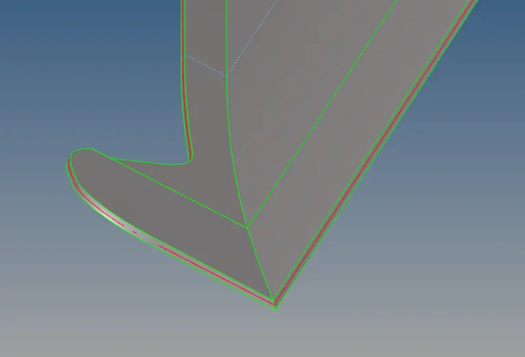
Once midsurfaces is generated by automidsurface tool , the surfaces that was not able to properly capture the mid surface of the component is generated manually by offsetting a duplicate surface to the middle of the component surface using surface edit tool.
Geometry Cleanup:
- After the mdsurfaces are extracted from the model, before meshing the mid-surface, geometry clean up of the surfaces are done.
- Geometry cleanup is done using autocleanup tool under geometry tab
- Clean-up will remove connectivity errors and restore the surface data to a perfect representation of the part.
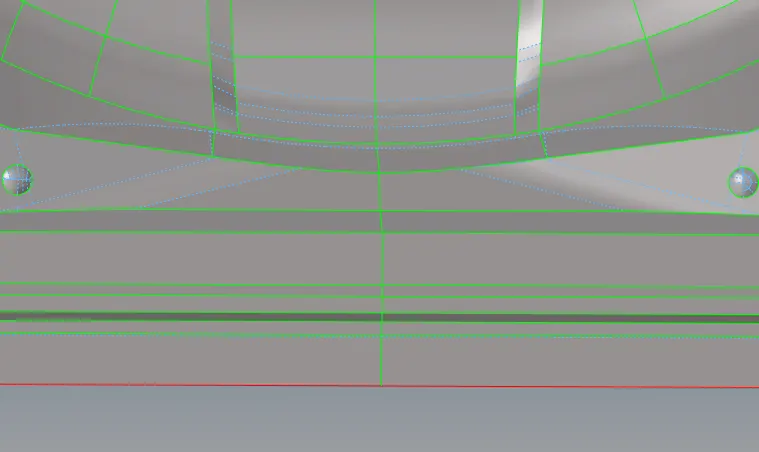
- After geometry cleanup is performed, additional edges as required are created and unwanted edges are toggled using quick edit tools (toggle edge, split surface) under geometry tab.
Meshing:
- After the cleanup is finished and each component is divided into smaller and simple surfaces to obtain proper mesh.
- The meshing is done by using automesh tool under 2-D tab with elements size as 5 and element type as quad.
- The meshing of each component is done surface wise from one small surface and is progressed into adjacent attached surfaces.
- After each small surfaces are meshed, quality criteria check is carried out inorder to clear any criteria violating elements at early stages itself.
- Criteria check is done using qualityindex tool and check elems tool under 2-D tab.
- Under check elems tool, quality criteria is set as follows:
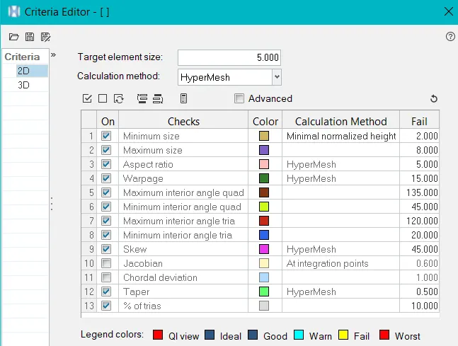
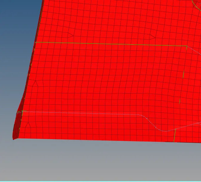
- After criteria is defined, Meshing of the surfaces are done using automesh tool under 2-D tab.
Quality criteria check:
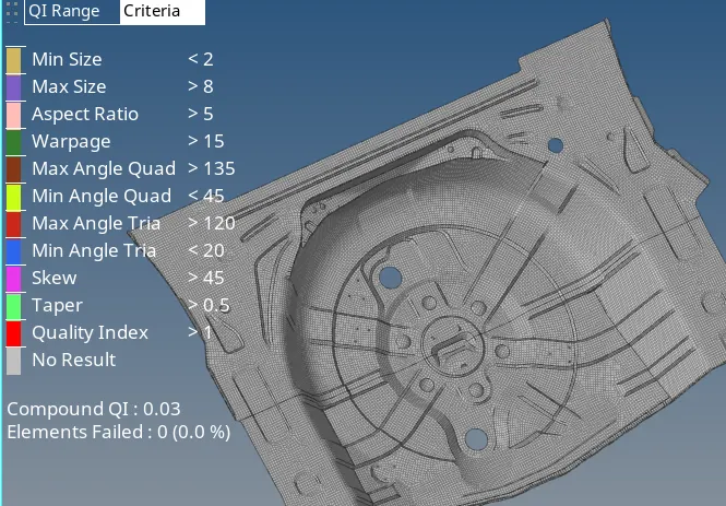
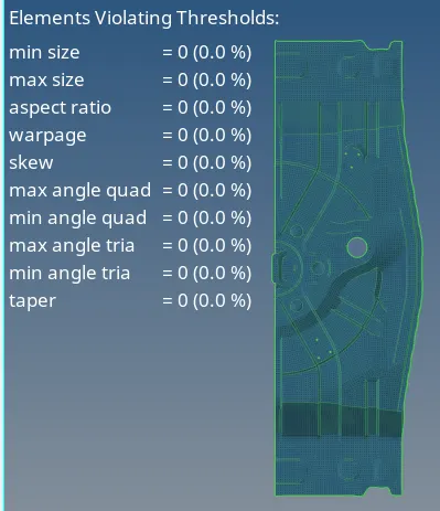
- The meshed elements of all components are checked using qualityindex tool.
- The elements violating the specified quality criteria are marked yellow and red.
- Cleanup tools like element optimize and place node within the qualityindex is used to optmise the violating elements.
- For elements which are not optimized to within the criteria range with qualityindex tool, elem cleanup tool is used.
- In situations where qualityindex and elem cleanup tools failed to rectify the violating elements, automesh tool is used to remesh the non-optmized elements.
- The elements of the all components are checked if any more violating elements are present.
- If present, the above steps are repeated until all elements fall under the given quality criteria.
Connectivity Check:
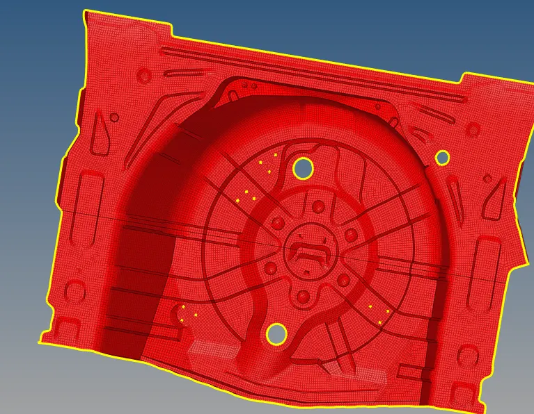
- After meshing, there may be some elements that may have connectivty issue with the adjacent elements which should be rectified.
- This is checked using edges tool under Tools tab. If any undesired edges are present, adjacent elements are selected and equivalence option is selected which will clear off the connectivity issue.
Assiging Property and Material:
- After meshing and quality checks, the elements are assigned with thickness and material.
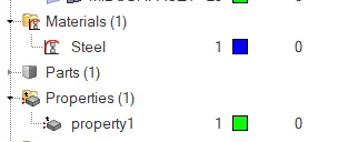
- Inorder to assign part thickness to the elements, a property component is created and thickness of 0.75mm is defined.
- Material collector is also created and named as steel and specific values are defined.
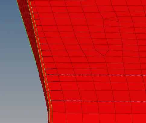
Above figure shows the elements perfectly fitting within the given model after thickness is assigned.
Conclusion:
- Hence generated the Midsurface of the given component and performed geometry clean up.
- Meshing performed on the generated midsurface with elements under the given quality criteria.
- Thickness and material is assigned to the created elements.