Week - 4 - 2D meshing for Plastic components
OBJECTIVE:
For the given Plastic Bottle Cap model,
- check for the geometrical errors and take the mid surface by suitable mid surfacing techniques.
- PID and Thickness assignment to all the mid surfaces.
- Mesh the Plastic Bottle Cap model with given element Quality criteria.
|
S.No |
Quality Criteria |
Value |
|
1 |
Target/Average length |
1 |
|
2 |
Minimum Length |
0.5 |
|
3 |
Maximum Length |
3 |
|
4 |
Aspect |
3 |
|
5 |
Warpage |
15 |
|
6 |
Skewness |
45 |
|
7 |
Jacobian |
0.7 |
|
8 |
Minimum Quad Angle |
45 |
|
9 |
Maximum Quad Angle |
135 |
|
10 |
Minimum Tria Angle |
30 |
|
11 |
Maximum Tria Angle |
120 |
|
10 |
Tria Percentage |
15 |
PROCEDURE:
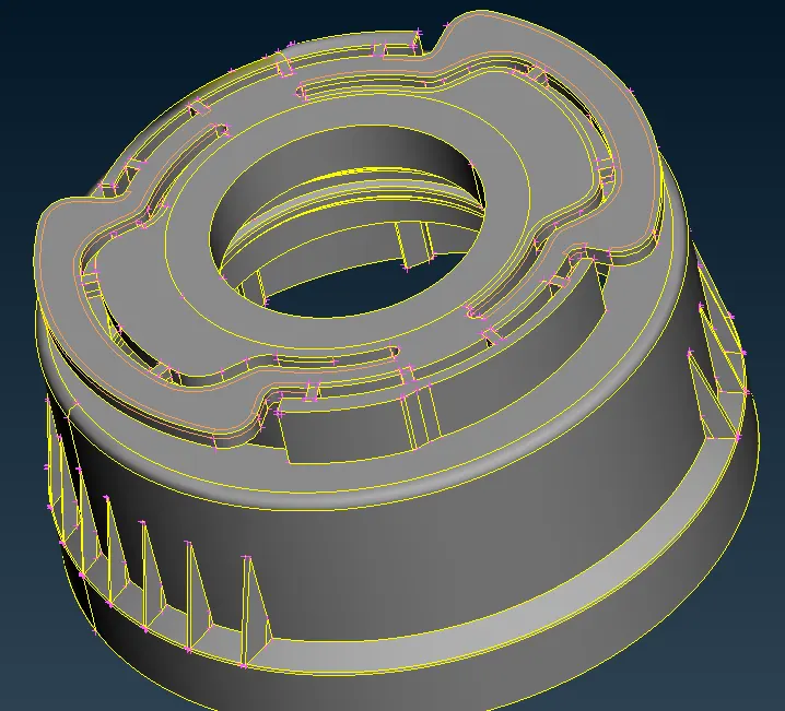
Import:
- The given file is imported to ANSA using
- FIle>Open>File Location>File
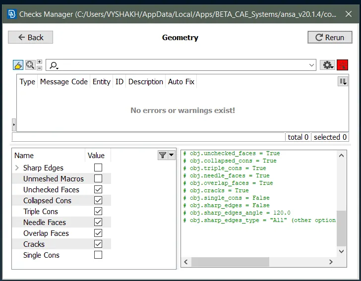
- After the file is imported, inorder to check for any connectivity issues, Geometry check of the model is performed.
- Any error present in the model was cleared and the geometry check was again performed.
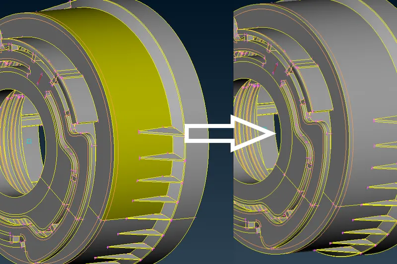
Orientation:
- The model orientation is corrected using the orient option under faces tab which makes the orientation of the whole model same at desired face.
Midsurface:
- After the geometry check and orientation of the model is completed, the midsurface of the moel is to be obtained inorder to perform meshing.
- To obtain midsurface, offset option under faces tab is used.
- To check for the offset distance, the thickness of the each parts should be measured, which can be done using measure option under utilities tab.
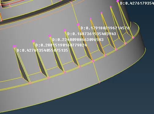
- It is found that, the thickness of the model varies at each part, hence the offset distance for each part is different.
- The midsurface of the geometry is created by offseting the surface to half of the thickness at each part.
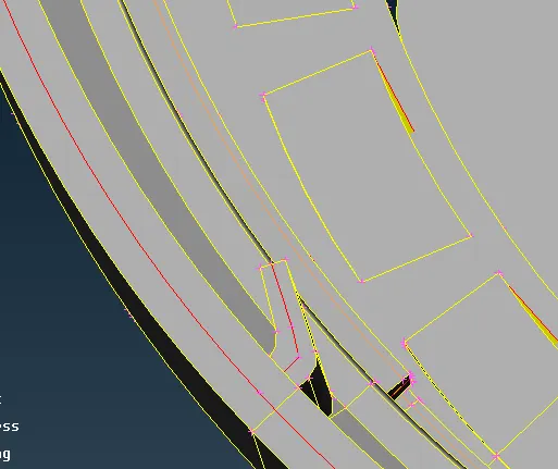
- Since there is difference in thickness and offset distance, some of the surfaces are found intersecting, which is intersected and deleted using Intersect tool and Delete faces tool.
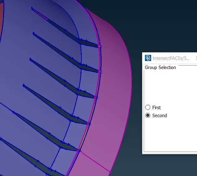
- middle surface of teeth and ribs are obtained by creating curve at the centre of the surface and then using New option under faces tab
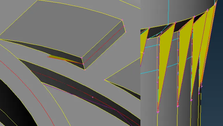
- Teeth midsurface and upper ribs of the model are created for one part and is then rotated using transform tool.
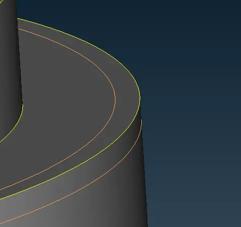
- Some of the fillets in the model are also removed using Dach tool to make the model easy to extract the midsurface as shown below:.
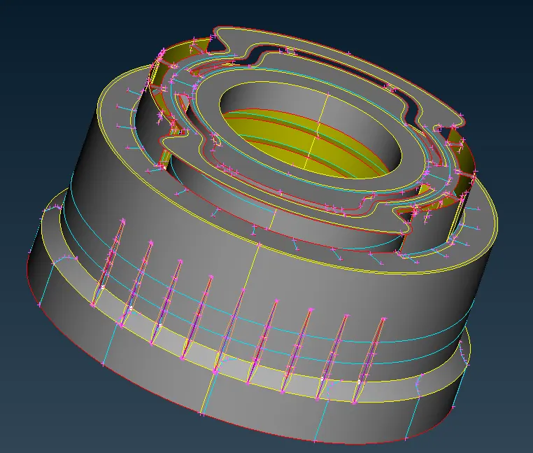
- Created midsurface is further divided into small areas usinng cut tool under macros tab under mesh panel.
- Also unnecessary divisions and sharp corners are avoided using join tool under macros tab under mesh panel.
Quality Criteria:
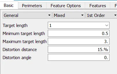
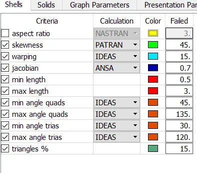
- Quality criteria and length parameters are defined as per given quality index table.
Property:
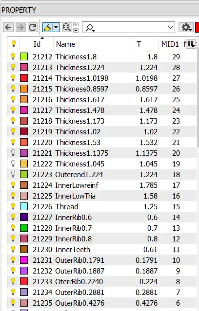
- PSHELL property is defined for each thickness model as shown below:
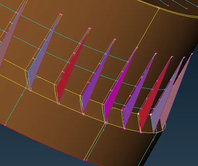
- Ribs with different thickness applied as shown below for specific thickness.
Material:
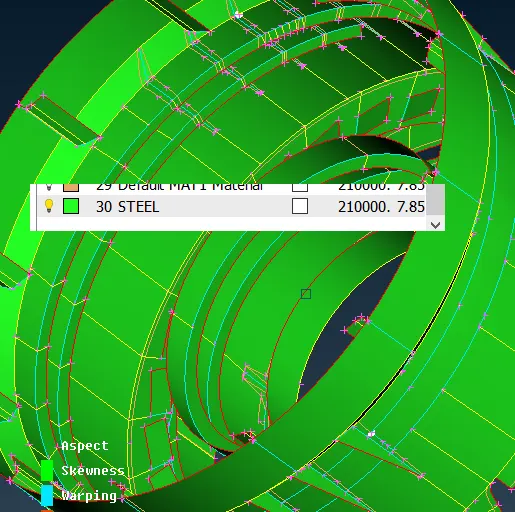
- Steel material is defined and the material is assigned to each of the created property:
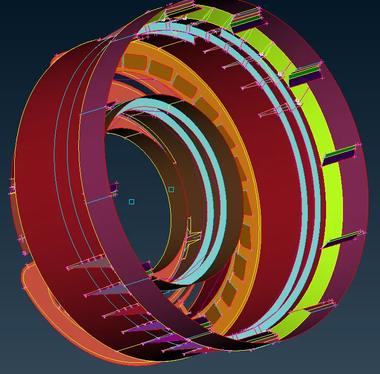
- Material is assigned to all the middle surfaces and property for different thickness is also assigned, and viewed under PID view.
Meshing:
- Meshing is progressed by meshing small divided surfaces one after the other.
- Meshing of each individual divided area is done using best option under mesh generation tab under mesh panel.
- Meshing is carried out with hidden view mode to ensure that any elements violating the specified quality criteria is eliminated once meshing of each small area of the part is finished.
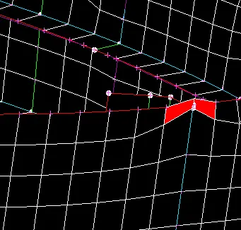
- During meshing, some of the element violated quality criteria, which is cleared using reconstruct option under ShellMesh tab in Mesh panel.
- Tria elements are corrected using Swap and split option under elements tab in Mesh panel.
- Similarly the whole mid surfaces of each part is meshed and any violating elements ar cleared off.
- Due to close;y placed triple cons are present in the model, it is very difficult to obtain mesh with all the elements following specified quality criteria. Hence these elements are not cleared off.
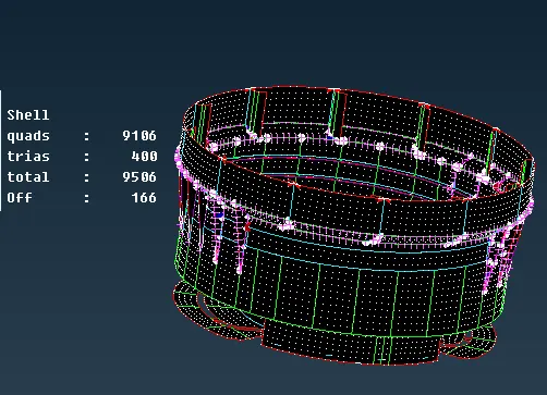
- here about 166 elements are violating the quality criteria but also not possible to eliminate.
- Hence these surfaces are meshed and the 2-D meshing of the given model is completed.
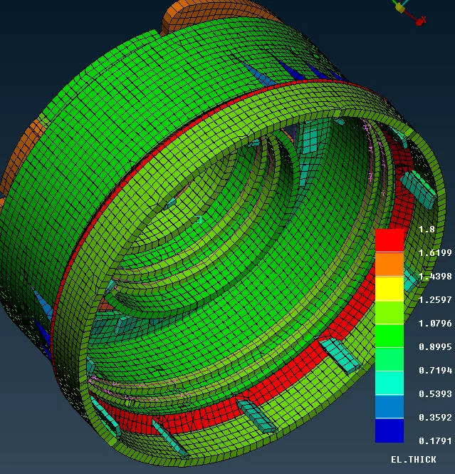
Enabling Thickness:
- Inorder to enable the assigned thickness on the elements, Quality Criteria tab is opened (F11).
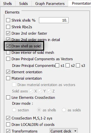
- Under Presentation Parameters, Draw shell as Solid option is checked.
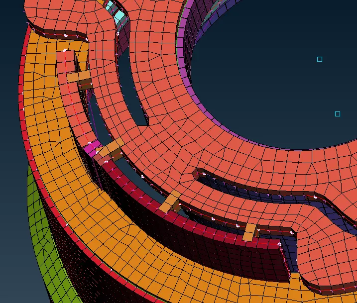
- Once applied, the elements are displayed with specified thickness
CONCLUSION:
- The midsurface of the given hood model was created.
- Quality criteria was defined and the midsurface was divided into small areas for better meshing.
- Meshing of the midsurface was performed using best mesh option.
- Elements violating the criteria was cleared to the maximum extent possible and smooth mesh flow was obtained.
- Property was created and applied for each part of the hood and original thickness was defined under each property.