Thermal Modeling Of a Battery Pack
AIM:
To Simulate Thermal Effects in a Battery Pack at various temperatures and Load conditions.
INTRODUCTION:
Electric Vehicles (EVs) are considered the future of transportation. Electric vehicles have gained more interest as a mode of transportation with the growing concerns over fossil fuel depletion and the increasing price of crude oil. A Variety of electric vehicles have been developed in recent years, including Pure electric vehicles (EVs), hybrid electric vehicles (HEVs), and plug-in hybrid electric vehicles (PHEVs). One of the most focused area in Electric vehicle development is the energy storage system, which is currently dominated by Lithium ion batteries. Electric Vehicless have manier advantages over conventional Internal Combustion engines including energy efficiency, instantaneous power, environmental friendliness and silent operation. The performance of EVs is greatly dependent on the battery pack.
The reaction between the anode and cathode produces certain level of energy in the battery required for traction which might also produce thermal effects over long or heavy usage. Battery performance is highly dependent on the working ambient temperature. Temperatures of the cells in a battery pack need to be maintained within its optimum operating temperature range in order to achieve maximum performance, safety and reliability under various operating conditions. Hence, a thermal management system is needed in order to enhance the performance and to extend the life cycle of the battery pack.
Poor thermal management will affect the charging and discharging power, cycle life, cell balancing and capacity of the battery pack. An approach to this issue is to alter the materials used in manufacturing of the batteries at the cell level. Another approach is to add thermal control components to provide suitable working conditions for batteries, referred to as a Battery thermal management system.
In a pack, the position of the battery may also lead to slight differences in the cooling effect and operating current, which may lead to a non-uniform temperature distribution. Less temperature uniformity results in the rapid decay of the life cycle of the battery pack. and aggravate the unbalanced discharging phenomenon and decreases the available energy for the battery packs.
This study is focused on simulation of Thermal effects stated above which affects performance and life cycle of the battery pack. It simulates impact of a faulty cell on performance and cell temperatures.
MODEL:
MODEL DESCRIPTION:
Cell Configuration:
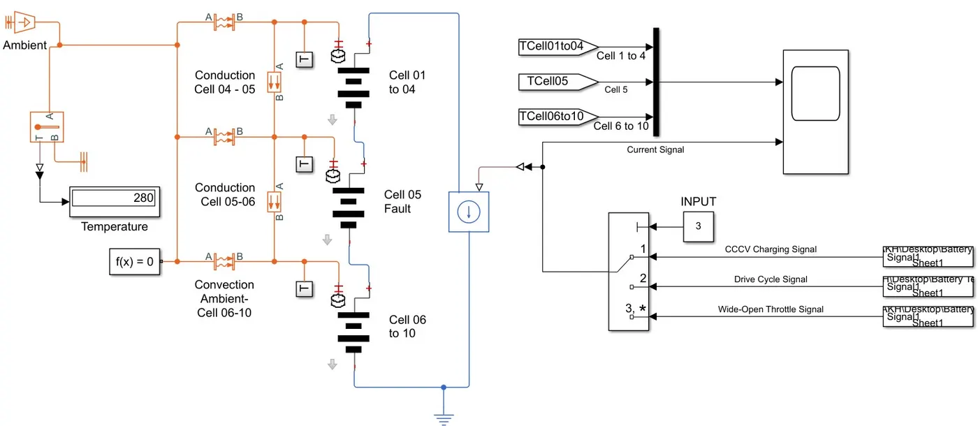
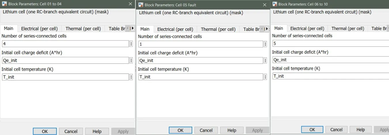
The Simulink Model displayed is a 10 cell Battery pack connected in series configuration. Out of the 10 cells, the cells are arranged in such a way that the heat produced in cells are dissipated to the atmosphere through convection. Cell-5 being in the middle of the pack, disspates heat through conductive heat transfer, taken up by Cell-4 and Cell-6. Hence Cell-5 is focused to show a different thermal characteristics than the rest of the cells in the Battery Pack due to unven heat transfer behaviour of the Pack considered.
Following figure shows the parameters described for the 10 cell in series configuration:
Additionally, Electrical and Thermal parameters of Cell-5 is modified since Cell-5 undergoes uneven temperature distribution and hence reduced performance. Cell-5 parameters are changed to represent the fault condition. The modified parameters are shown below:
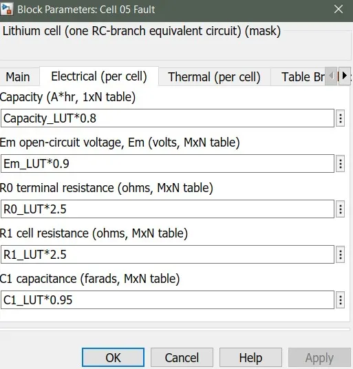
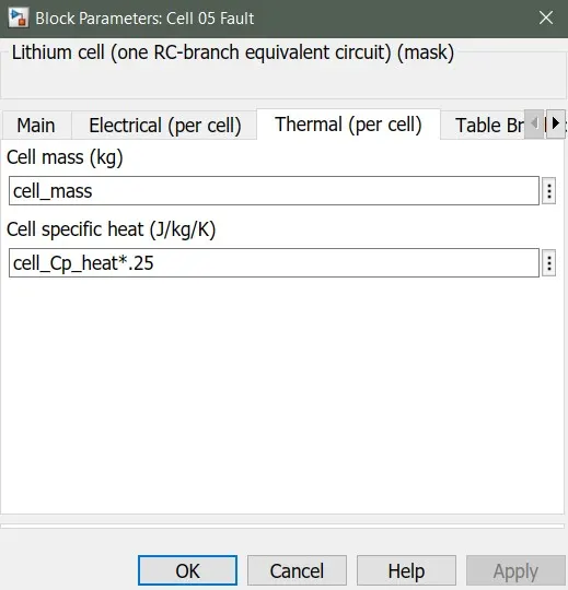
Major modifications made to cell-5 are increasing resistance and decreasing capacity, Open circuit voltage and cell speciifc heat capacity.
Heat Transfer Monitoring:
Convective and conductive heat transfer characterstics of cells are understood by the use of Conductive Heat transfer and Convective Heat transfer blocks. These are calculated with reference to temperature difference during simulation, cell area and heat transfer coefficient of cells. Figure represents Conductive and Convective Heat Transfer Block respectively:
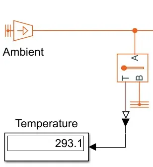
The Ambient Temperature is predefined through MATLAB Script (T_init) and a display is introduced to notify the Ambient Temperature set during simulation. A temperature Sensor is used to detect the predefined initial Temperature. The Ambient temperature display setup is shown below:
Input Current Signal:
Three types of scenarios are provided to the cell inorder to simulate the thermal effects of the 10 cell series battery pack.
- Charging Mode
- Driving Mode
- Wide Open Throttle Condition
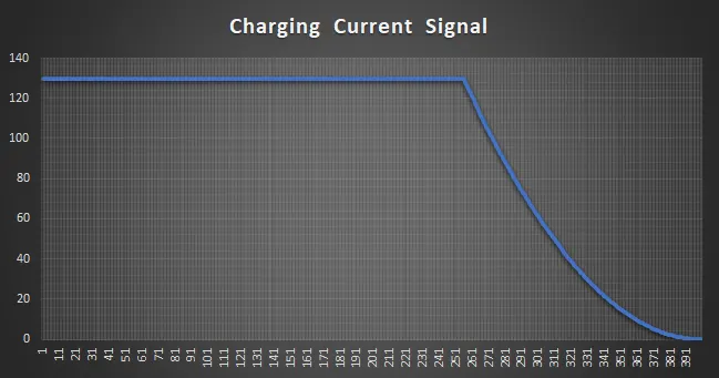
- For simulating a charging mode, A current profile similar to a CCCV (Constant Current Constant Voltage) charging is introduced.
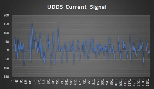
- For Driving mode, a current profile obtained from UDDS Drive cycle is introduced.
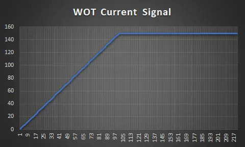
- For WOT condition, a different current profile is introduced.
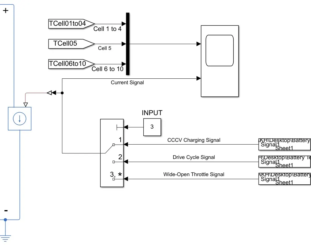
A Controlled current source is used through which the current signal is fed to the Battery pack. A multiport switch is used inorder to select the type of scenario to be simulated (Charging, driving or WOT Condition). Current sgnals are imported by using from spreadsheet blocks which are connected to the switch. Also the signal is parallely fed to the Scope block displaying the temperature curve inorder to view the type of current signal simulated. Following figure shows the different current signals provided as input to the Model.
SIMULATION RESULTS:
Simulation is performed for 3 different scenarios as specified, each at different temperatures to understand the variation of thermal effects in the battery pack with change in ambient temperature of the battery pack. The duration of simulation performed for Charging, Driving and WOT condition is 400 seconds, 1370 seconds and 220 seconds respectively.
1) Charging Mode:
Temperature = 240K
Temperature = 280K
Temperature = 305K
Temperature = 350K
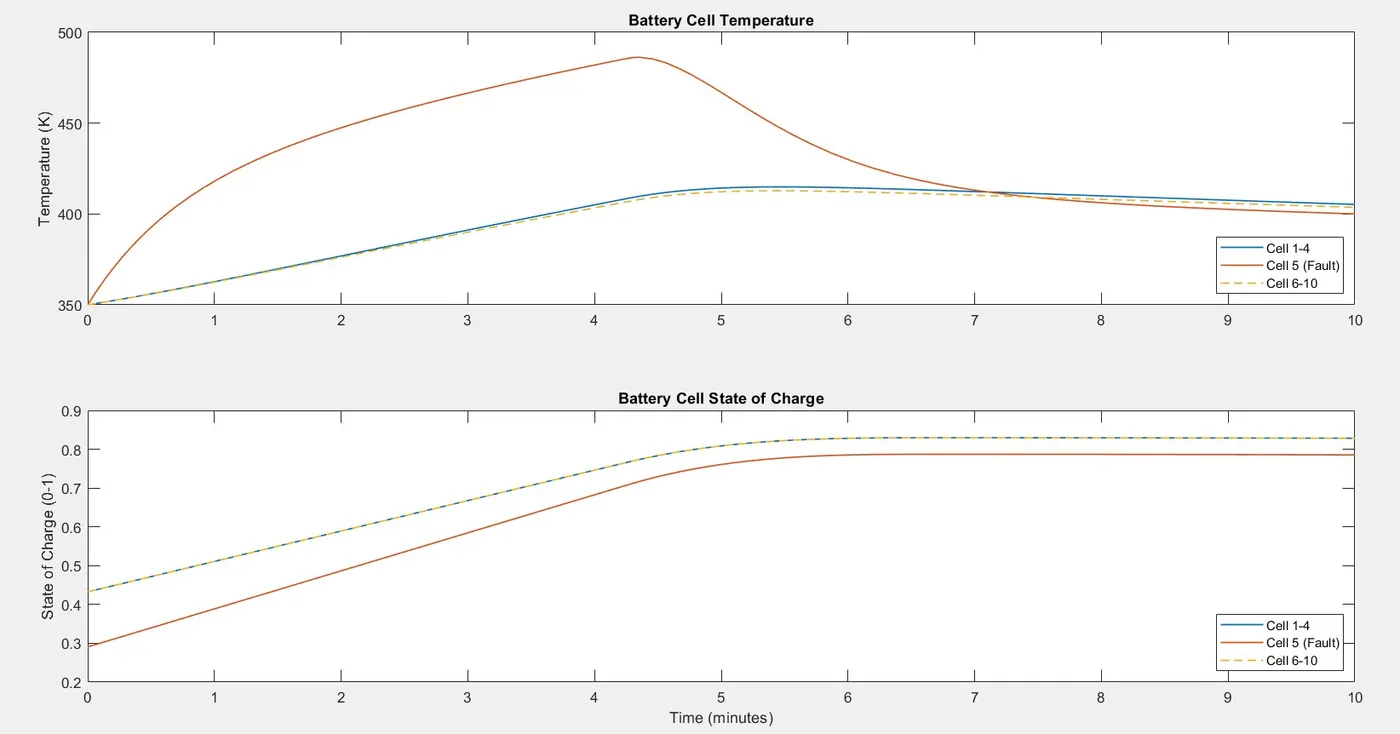
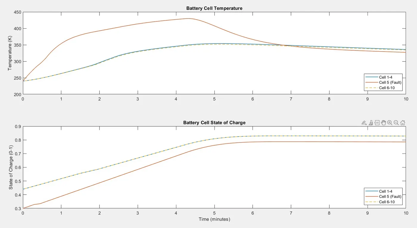
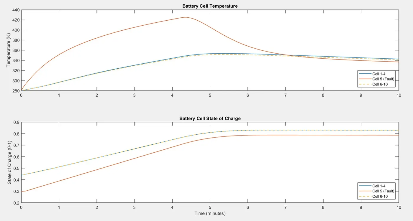
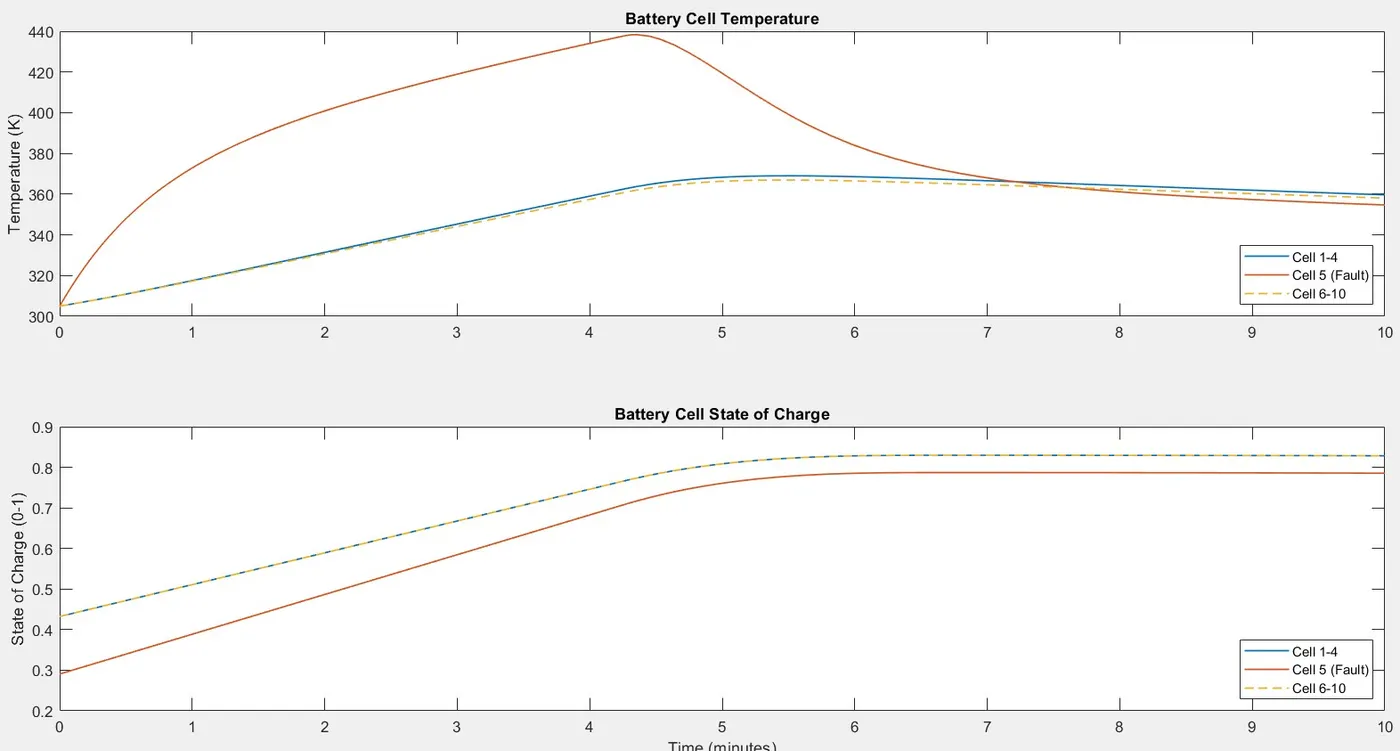
- Above plots shows the variation in cell temperatures and State-Of-Charge levels during the simulation.
- Charging signal is given for 400seconds in which Constant current charging occurs for the first 255 seconds followed by constant voltage for the rest of the simulation. The simulation in Charging mode is performed at 4 different Ambient temperatures.
- The State-Of-Charge of Cell-1 to Cell-4 & Cell-6 to Cell-10 starts from 43% and reaches a value of 83% at end of the simulation. Whereas the Cell-5 starts at 29% and gets charged only upto 78%.
- Plots clearly shows the variation in temperature range of Cell-5 from rest of the cells in the battery pack at each predefined Ambient temperature.
- Cell-5 shows a sudden increase in temperature while charging while other cell temperatures tend to rise in a gradual manner and continues till Constant Current charging is implemented and then falls down to the temperature of rest cells in the pack.
- With increasing ambient temperatures, the temperature rise of Cell-5 is about 100K more than rest of the cells which is a major concern that may lead to thermal fatigue to the rest of the cell or the entire battery pack.
- The increase in temperature is due to the increased thermal resistance that may develop in a cell which is simulated.
2) Driving Mode:
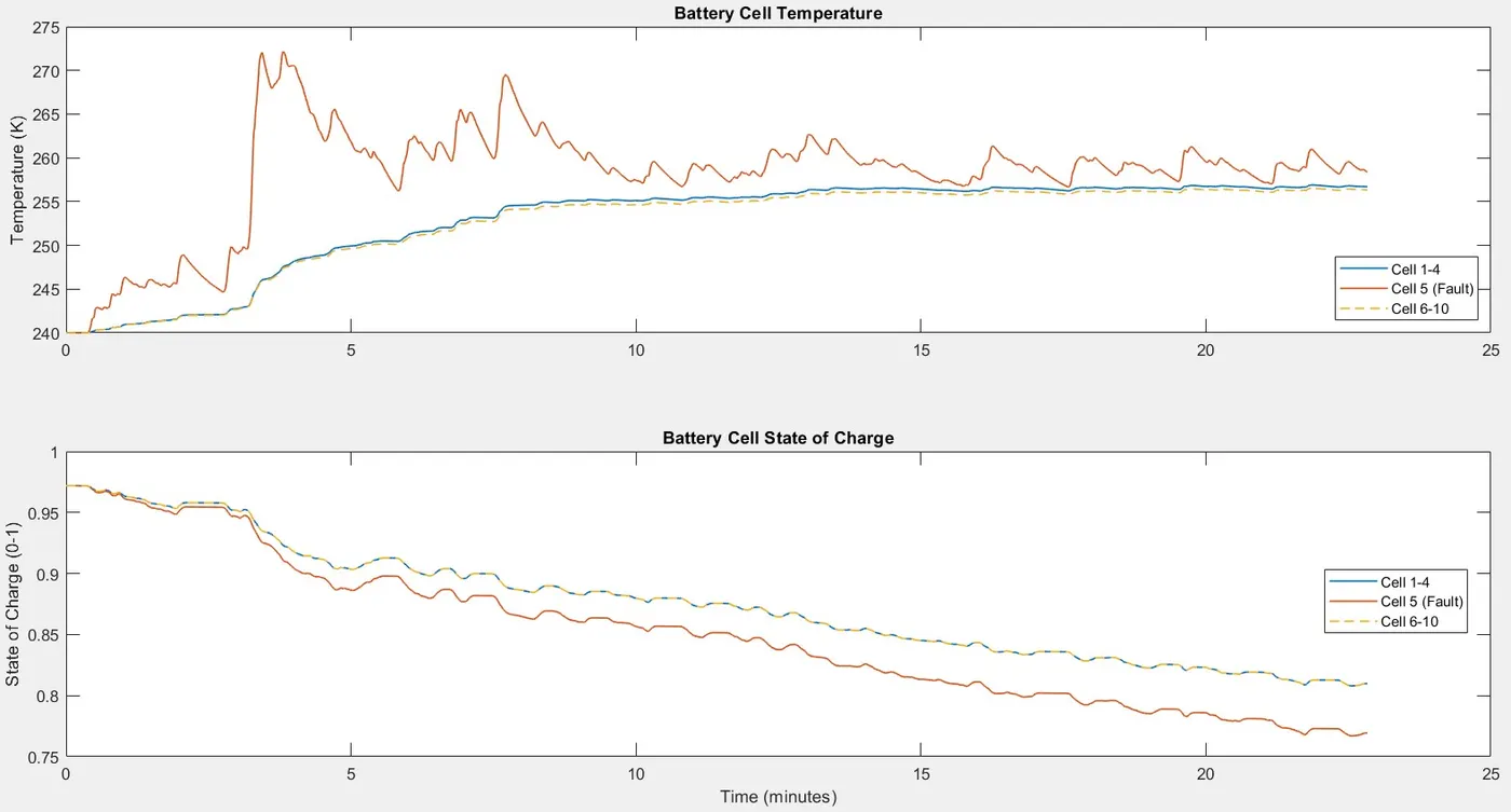
Temperature = 240K
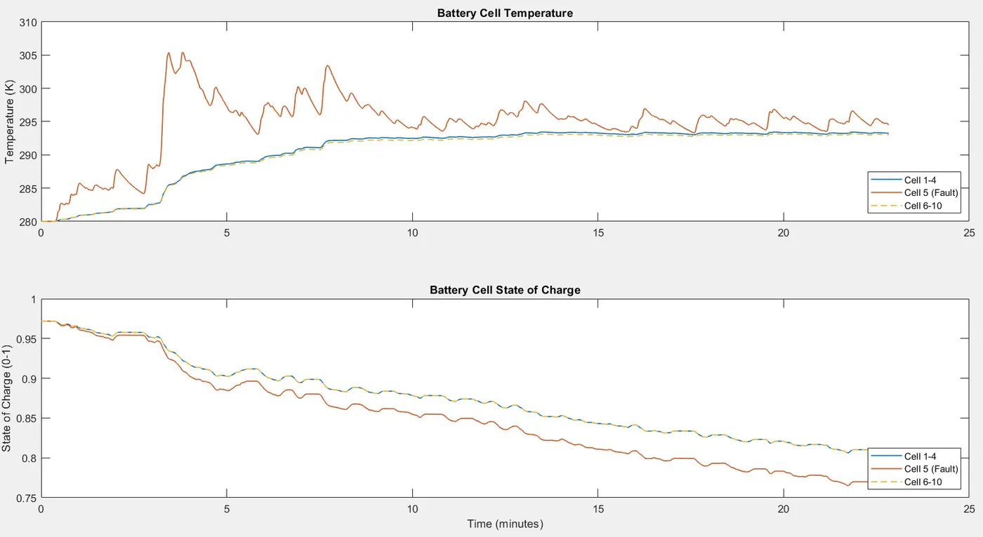
Temperature = 280K
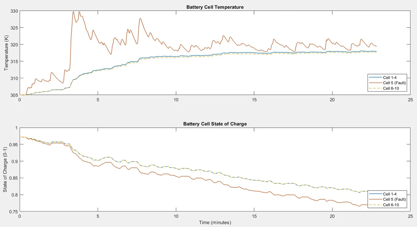
Temperature = 305K
Temperature = 350K
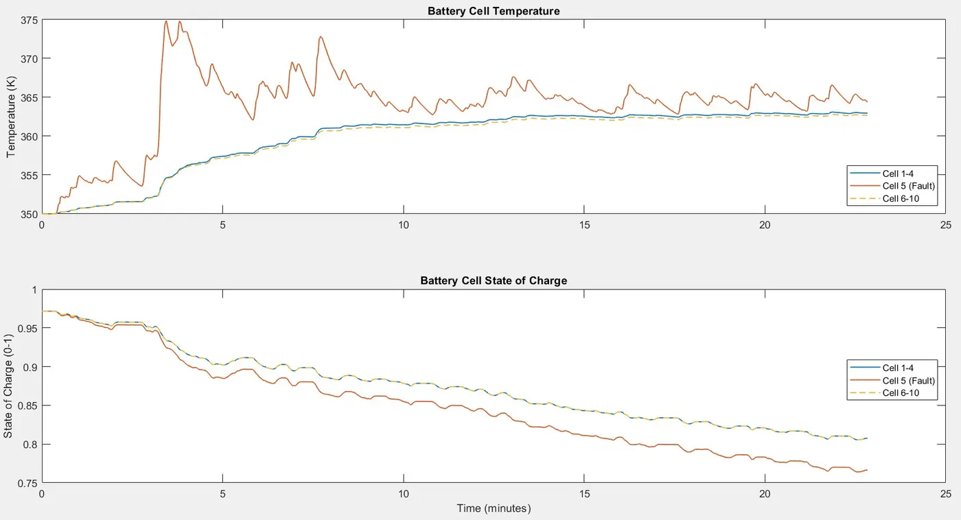
- For simulating a driving mode, UDDS Drive cycle data is taken as reference and corresponding current signals are given to the model as input current signal. Being a drive cycle data, both discharging and charging signals are included throughout the simulation. The simulation is performed for a period of 1370 seconds.
- The State-Of-Charge of the pack initially at 97% gets discharged after simulation in a different trend. The Cell-5 concentrated having fault gets discharged to 76% while rest of the cells having 80% SOC. This leads the battery pack to be under utilised where further usage of the battery pack may result in getting cell-5 to get fully discharged, while rest of the cells having left out with unused capacity.
- The peak current demand in this mode occurs at around 205 seconds, which creates a very steep temperature shoot up in Cell-5 at that instant. Temperature rise of about 30K takes place instantaneously which may lead to the deterioration of battery life.
- The temperature profile of Cell-5 when compared to driving signal shows steep rise in temperature when high current signals are encountered whereas rest of the cells in the pack shows an averaged gradual increase without much temperature peak rises throughout the simulation. Hence this condition creates temperature shock deterioration in cell-5 alone and failure of the same may result in failure of the entire Battery Pack.
2) Wide Open Throttle Mode:
Temperature = 240K
Temperature = 280K
Temperature = 305K
Temperature = 350K
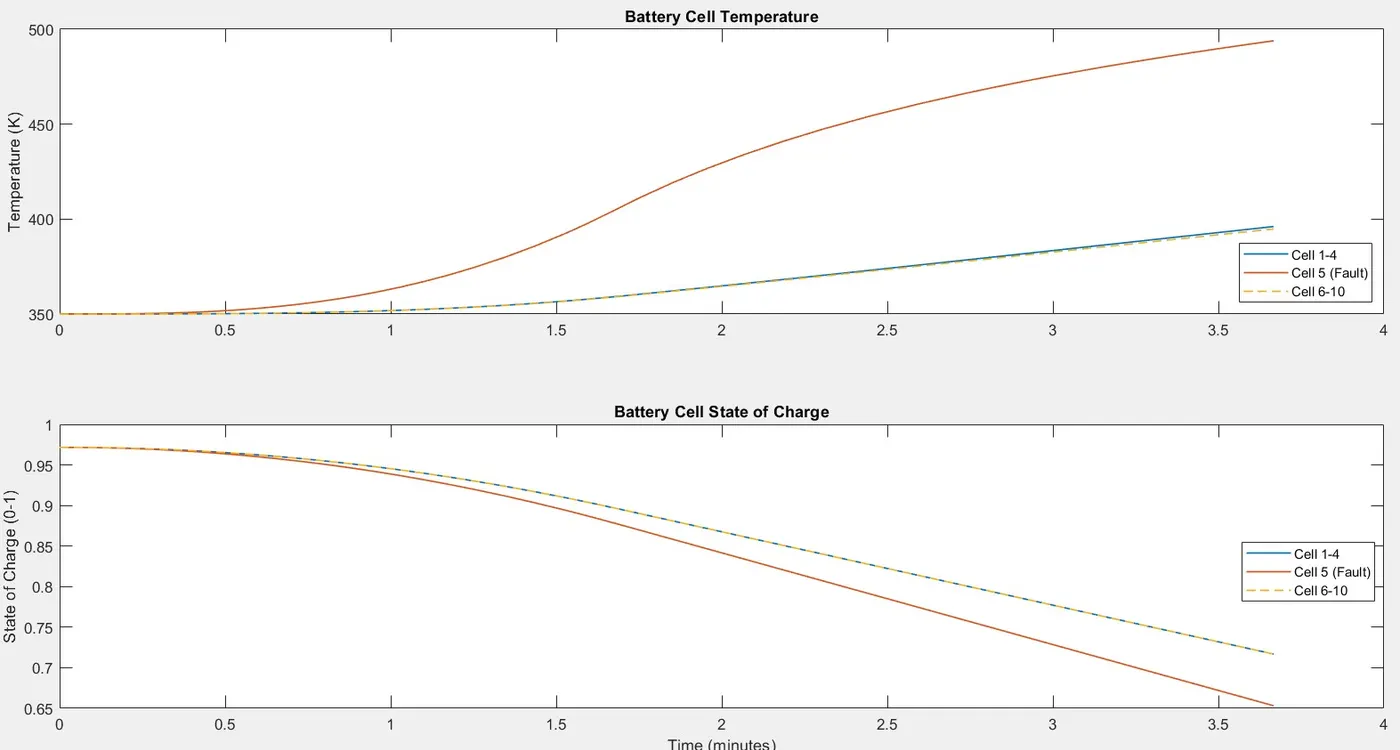
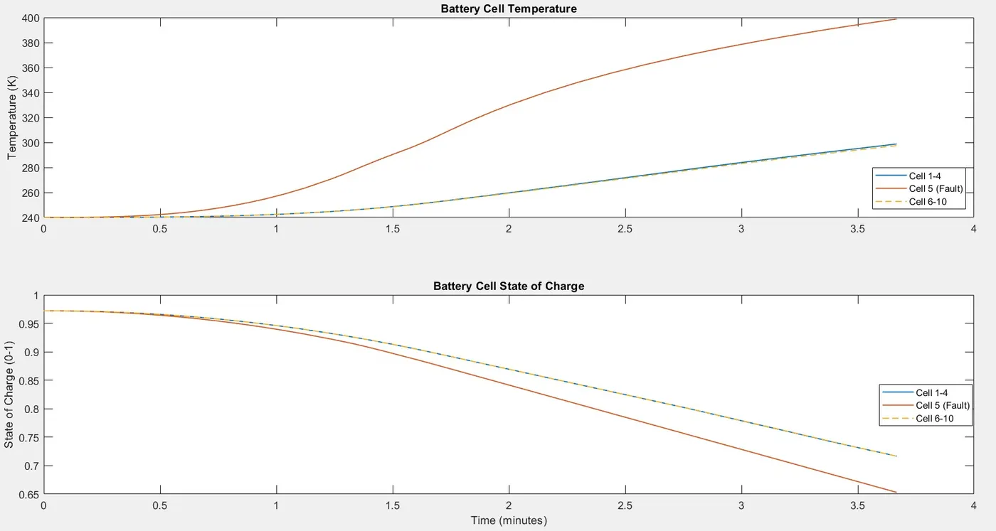
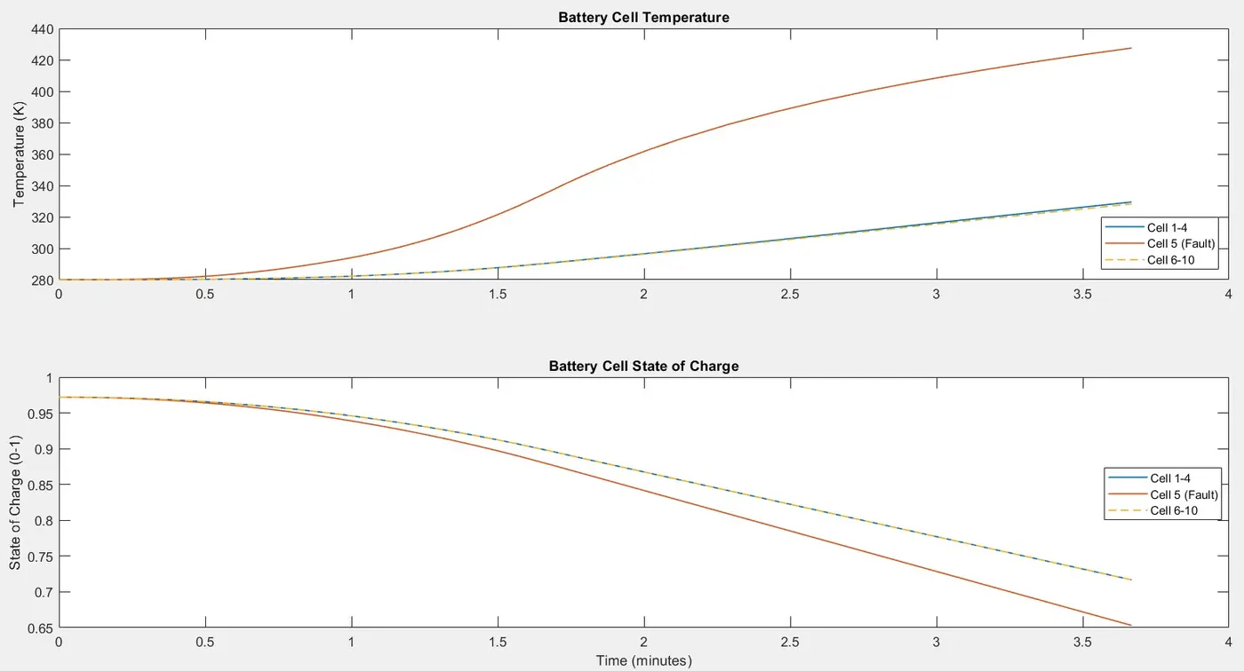
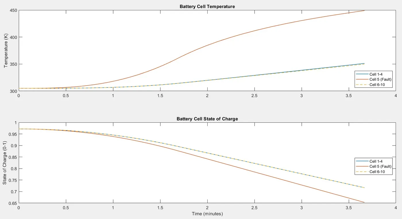
- For simulating the Wide-open-Throttle condition, a steeply rising current signal is applied till 100 seconds followed by steady current till end of the simulation.
- The simulation is run for 220 seconds under 4 different ambient temperatures. Results for every ambient temperature shows a similar thermal behaviour for every cell in the battery pack. Further simulation shows a very high temperature rise in Cell-5 when compared to the rest of the cells in the battery pack.
- At ambient temperature of 240K, the cell-5 temperature shoots up to around 400K under 4 mins which may cause severe failure to th cell and thereby the whole battery pack. Similarly, for changing ambient temperatures, the shoot-up in temperature in Cell-5 occurs and is found to increase with increasing ambient temperature.
- An average of 100K difference is observed between cell-5 and the rest of the cells in the pack. The steep rise in temperature due to the faulty cell is not admittable which causes fatigue to other cells and may lead to overall failure of the battery pack.
Following figure shows the highest temperature gained by Cell-5 at different ambient temperatures:
Cell-5 Temperature Comparison:

It clearly displays the higher temperature rise at different ambient temperature conditions during WOT condition and Charging condition where high amounts of loads acts upon the battery pack when compared to a normal driving signal condition.
CONCLUSION:
Battery or Cell performance rely upon a desired temperature range in which the performance and life proves to be excellent. But with varying temperatures in the operating environment of a battery, the performance and life is affected where the cell properties changes which maybe different for each cell. This variation in the cell performance due to thermal factors are simualted for 3 different scenarios and results displays variation in cell capacity and thermal behaviour for a faulty cell and rest of the cells in the pack. Such a variation in property leads to under-utilization, under-charging or vice versa which leads to deterioraton of the battery pack much earlier than designed life. Since simulation is focused on a series type connected battery pack, fault in a single cell may lead to the loss of entire battery pack.
Focusing a faulty cell in the pack, the variation in temperature and capacity from the rest of the cells in the battery pack is observed. High temperatures attained by the faulty cell may lead to failure of that particular cell and may even cause thermal stress on the adjacent cells and may also lead to the fault situation of more cells in the battery pack. A cell level monitoring system can be incorporated which helps to level the variation in cell parameters and might help the battery to work effectively for its designed life and performance.