Radar Mast & Final Assembly of Yacht
Modelling a Yacht with Solidworks
OBJECTIVE:
- To model different parts of a Yacht
- To assemble each parts of yacht to create the full model
INTRODUCTION:
- This project is focused in partwise modelling of the Yacht and then assembly of the parts together inorder to obtain the full Yacht model
DESIGN METHODOLOGY:
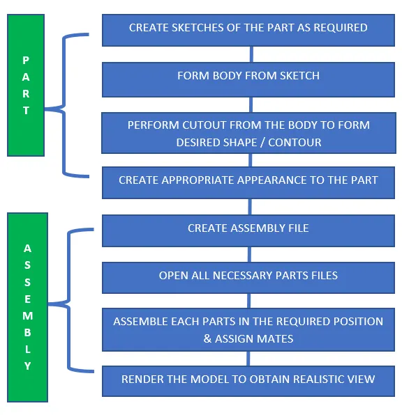
PROCEDURE:
Propeller:
- New part is opened,
- Sketch is made to make the centre part of the propeller
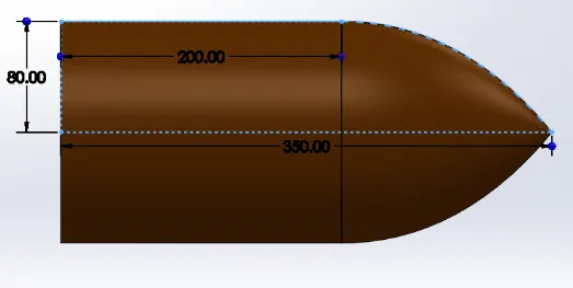
- Revolve option is used to create the solid centre part of the propeller from the sketch.
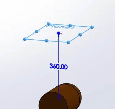
- A new reference plane is created parallel to top plane at a distance of 360mm from the centre of the propeller body
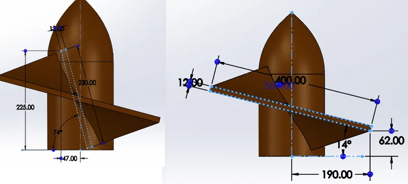
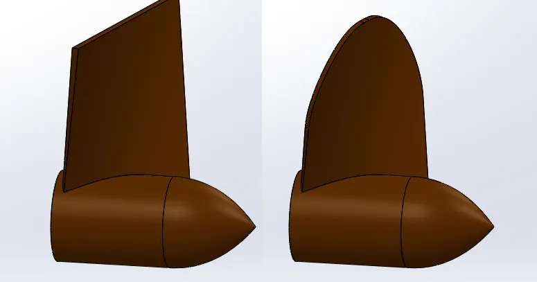
- New sketches are made on the Top plane and the new plane as shown and lofted surface option is used to create the propeller fin body:
- Fillet option is used to create a smooth rounded edge to the fins:
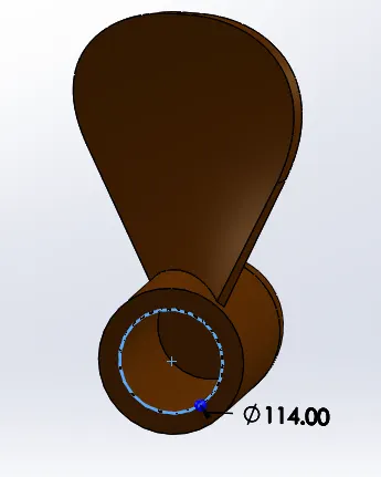
- A sketch is made on the flat face of the propeller body and extrude cut option is used to remove some material:
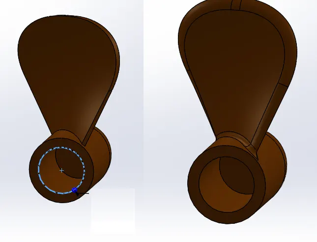
- Fillets are made on the fin edges
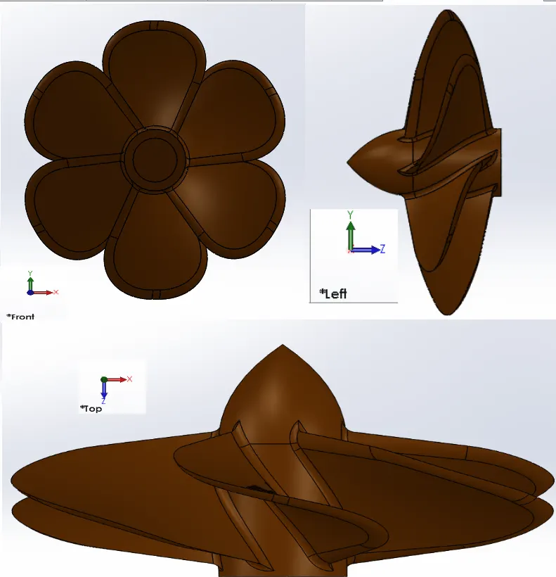
- Finally circular pattern option is used to create a total of 6 fins on the propeller body:
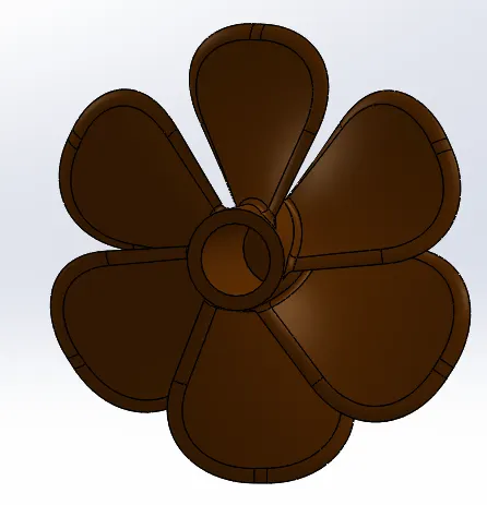
- Hence modelling of the propeller is completed as shown above.
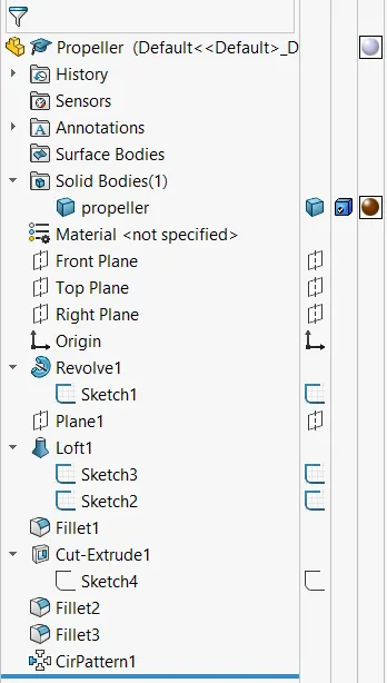
Model Tree:
Front , Side and Top View of propeller Model:
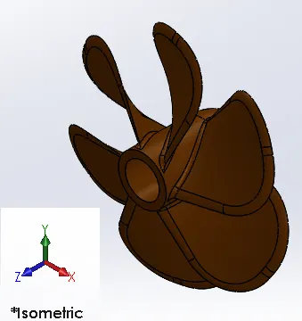
Isometric View:
RADAR:
- New part model is opened,
- Sketch is made on the right plane as shown:
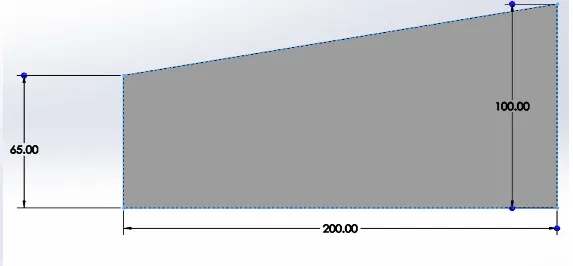
- Extruded base option is used to create a solid body from the sketch:
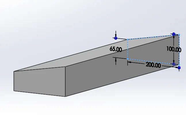
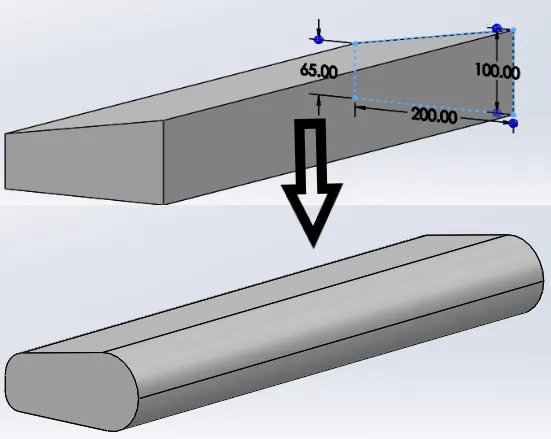
- Fillets are created on the edges of the solid body:
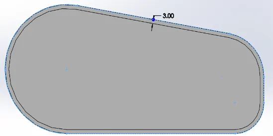
- The external edge is offset to 3mm outwards :
- Extrude option is used to create the end part of the radar:
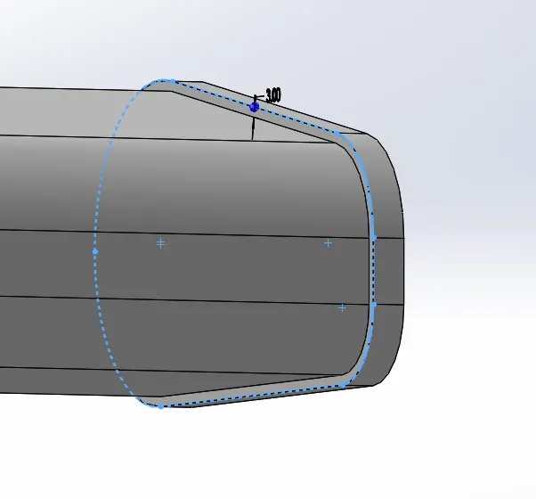
- Newly created outer edge is offset inwards in a new sketch and a small circle is extruded on the face:
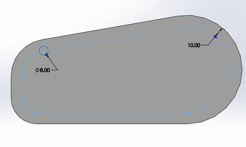
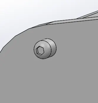
- On the extruded circle, fillet is created, and a polygon is sletched and extrude cut is used to create a bolted pattern:
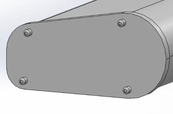
- Next reference ponts are created on the plain face and linear sketch pattern option is used to create the bolt pattern on all the four sides of the radar side face:
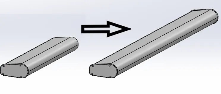
- Fillets are created on the edges and mirror option is used to create the complete radar body:
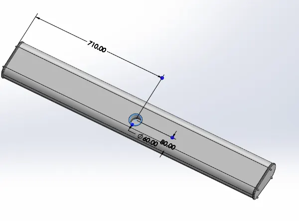
- Mounting hole on the radar body is sketched on the bottom plane face, extruded cut option is used to remove material and fillet on the edges are also provided:
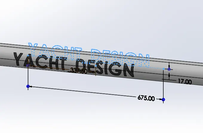
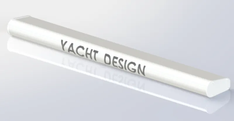
- Finally Split line option is used to insert a text to project a text on the radar body:
- White appearance is given to the model.
- Hence modelling of the propeller is completed as shown above.
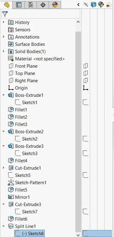
Model Tree:
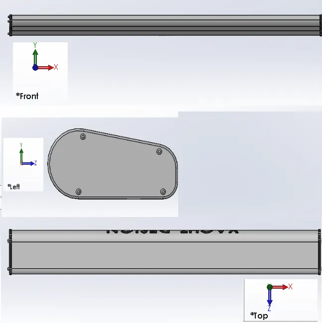
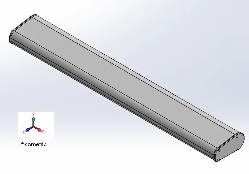
Front, Left Side and Top View of the Model:
isometric view:
BluePrint Setup:
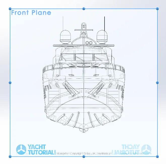
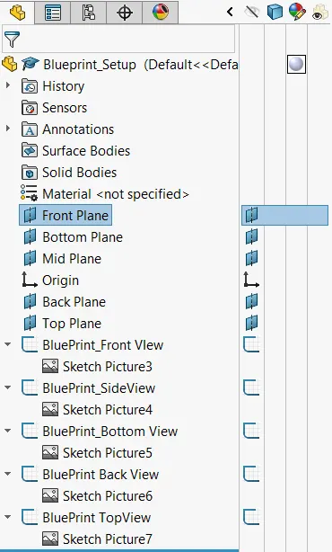
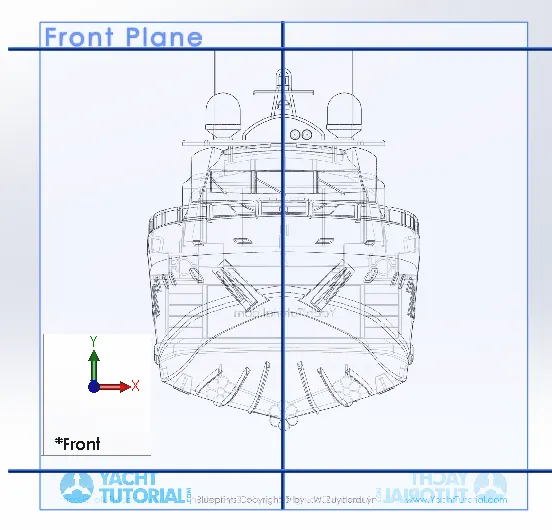
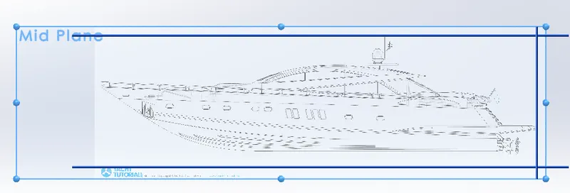
- Initially Sketch picture of Boat Front view is inserted on to front plane and named BluePrint Front View:
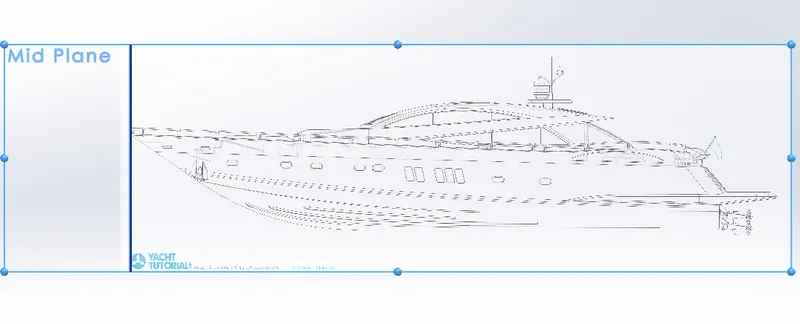
- Then on the right plane Sketch picture of Boat side view is inserted and named as mid plane
- Sketch is then named BluePrint Side View.
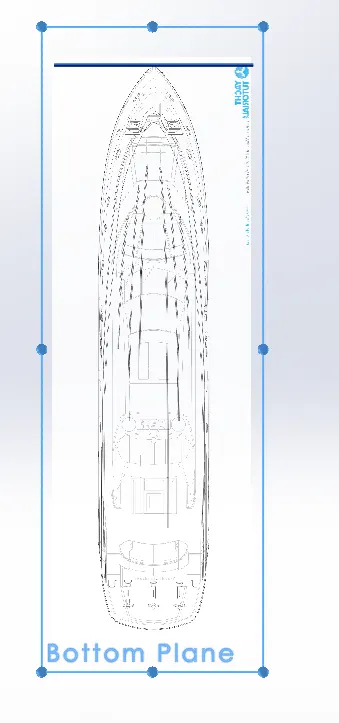
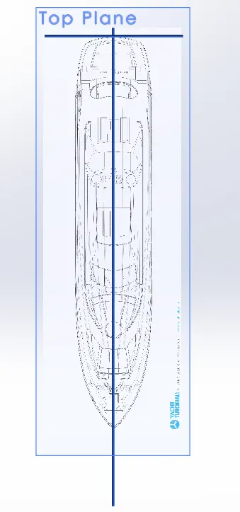
- Then the top plane is renamed to Bottom Plane and then Sketch picture of boat bottom view is inserted
- This is then renamed to Blueprint Bottom View.
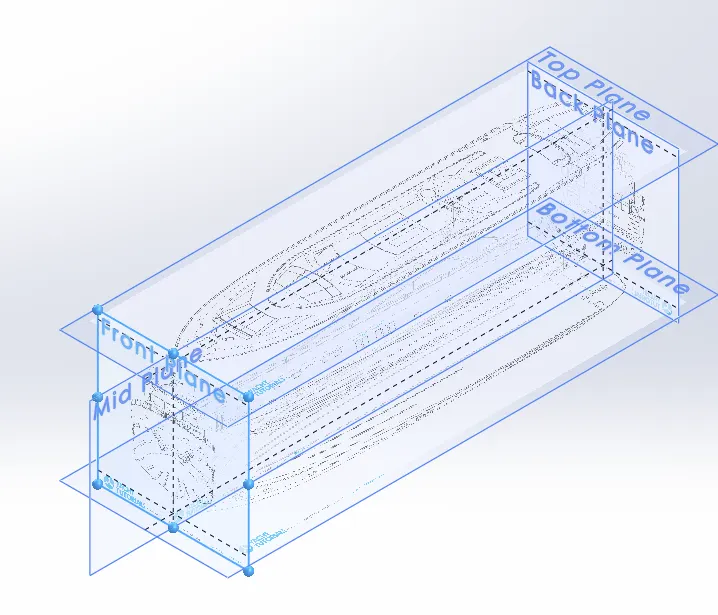
- Next, a reference plane is created offset at a distance from the front plane and is named Back plane.
- Sketch picture of boat back view is inserted on the back plane and is named Blueprint Back View.
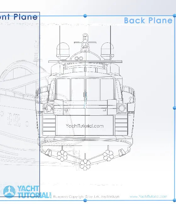
- It is made sure that the front of the boat image and the back ressembles the correct orientation of the boat.
- Next a reference plane is created offset at a distance from the Bottom plane and is named Top plane.
- Sketch picture of boat top view is inserted and is named Blueprint Top View
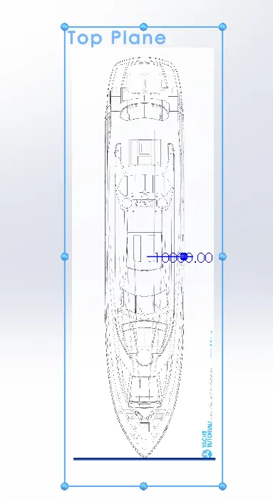
- Hence setting up the Sketch pictures at different planes are finished.
- All the sketch pictures are made 40% transparent while inserted.
Model Tree:
Front View:
Side View:
Top View:
Isometric View:
Hull:
- initially sketches are made inorder to capture the Yacht hull part.
- Projected curves are used to combine 2 different sketches in 2 different planes to obtain 3-D curve which fits the Hull part.
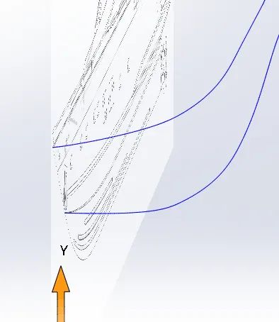
- Lofted Surface option is used to create the hull outer surface from the curves constructed:
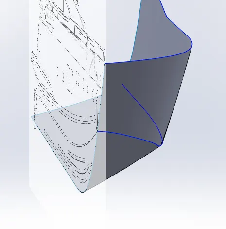
- Fill surface option is used to create a solid body from the lofted surfaces created.
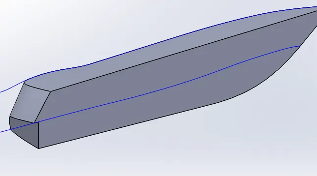
- Shell option is used to create the body thickness
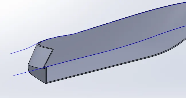
- Base extrude option is used to create surfaces as per the blueprint and also Extruded cut option is used at places to match the hull contour:
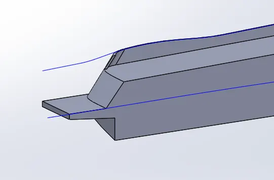
- Windows and cable slots are sketched and extruded cut option is used at required places:
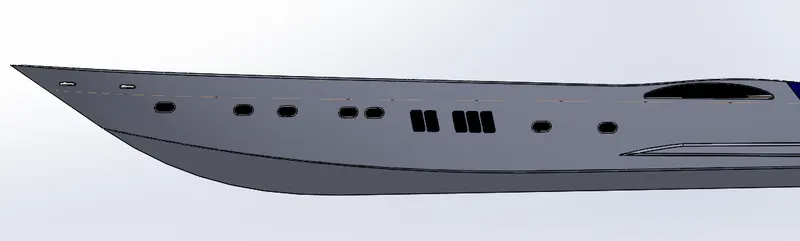
- Stair profile is extruded using reference sketches :
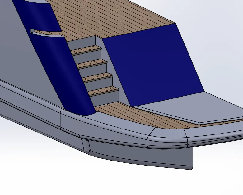
- Additional features are sketched and extruded out:
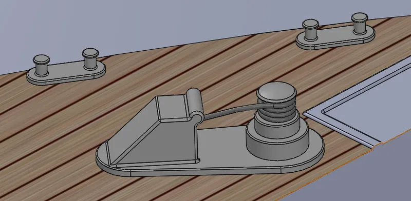
- Similarly features on the rear part is also sketched and extruded out:
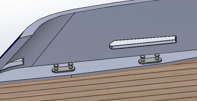
- Sketch of railing is created in two planes and projected to obtain the correct railing profile:
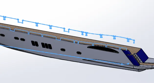
- Railing body is created from the curve using Sweep base option:
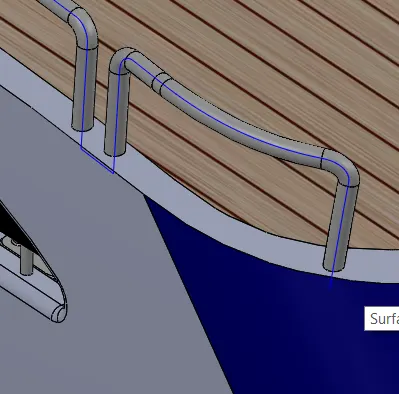
- Propeller mount and Stabilizer are sketched and extruded/revolved to create the body from sketch
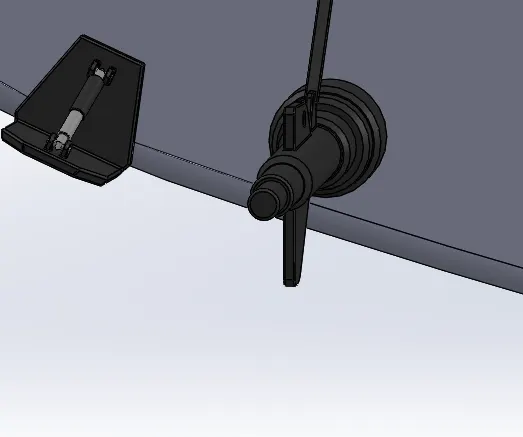
- Garage Part is extruded out:
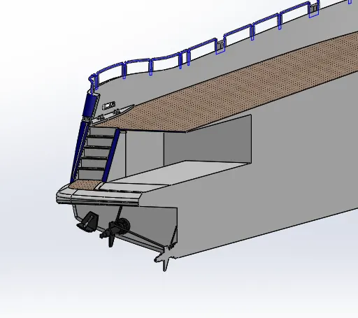
- Extruded part is saved as new part file named Garage Door.
- The body is then mirrored across midplane to obtain the full hull model of the yacht:
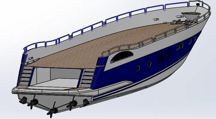
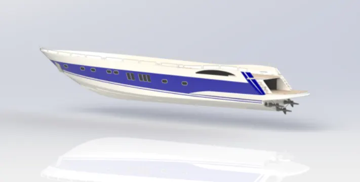
- Appearances are defined as shown using different colours and decals.
- Hence Modelling of the Hull part of the Yacht is finished as following the above steps.
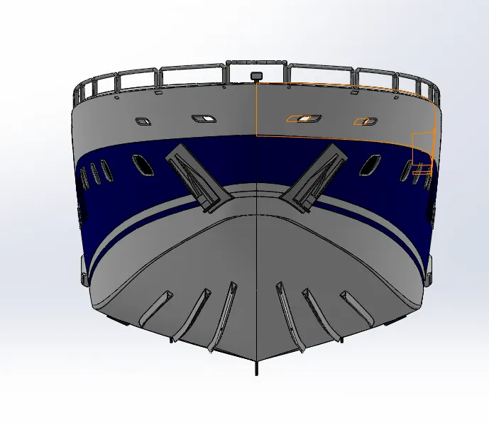
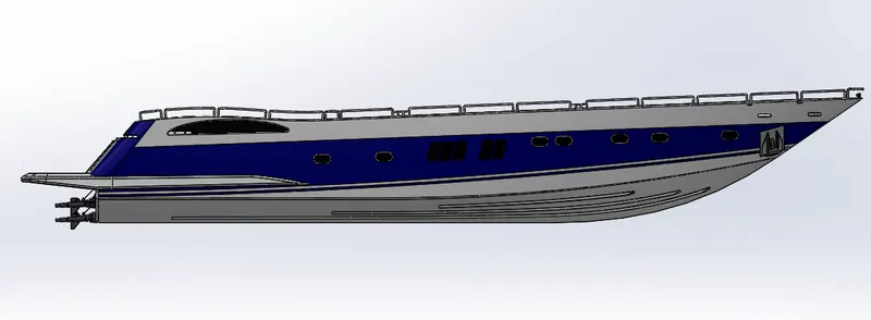
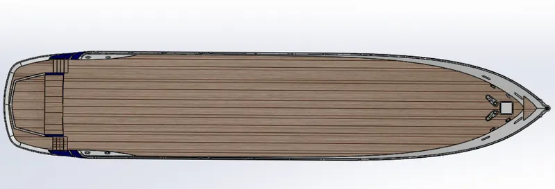
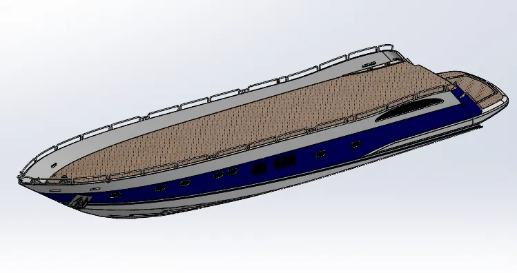
- Different standard views of the Hull model is given below.
Front View:
Side View:
Top View:
Isometric View:
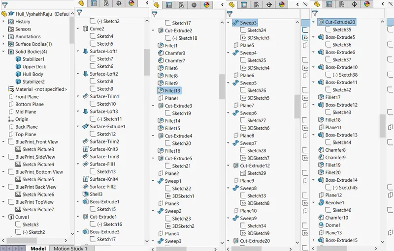
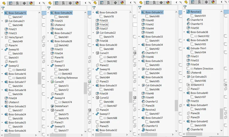
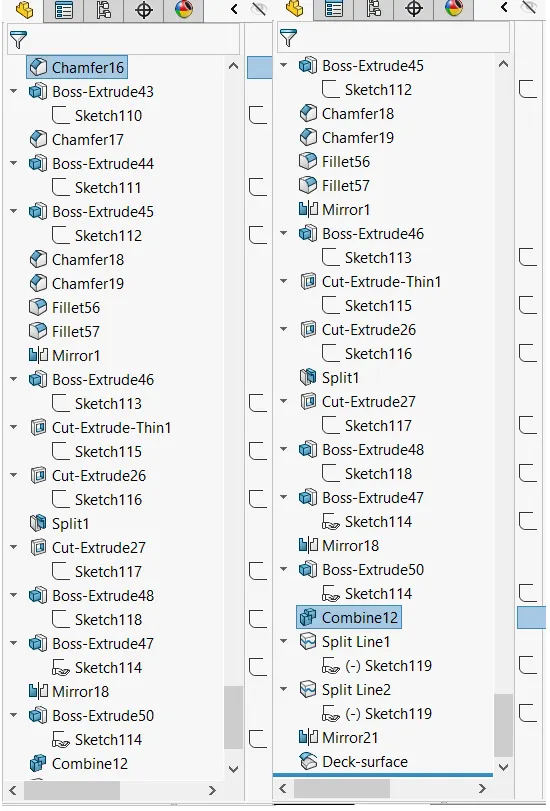
Model Tree:
GARAGE DOOR:
- The cutout portion from the Hull body is saved as a seperate file named as garage Door.
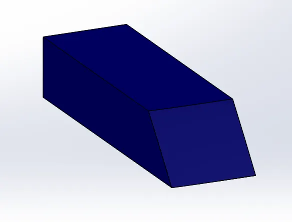
- A small portion of this surface is kept removing the rest using extruded cut option:
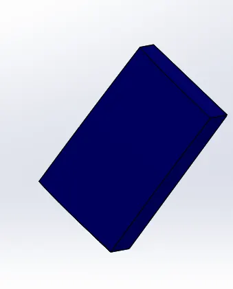
- Additional features are created with shell, fillet and extrude cut options.
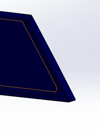
- Mirror option is used to create the other half of the door.
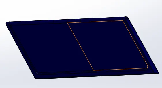
- A plane is defined at a distance from front plane to insert text on the plane.
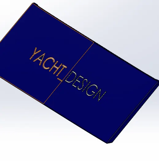
- Extruded cut option is used to create a cutout of the text on the door body:
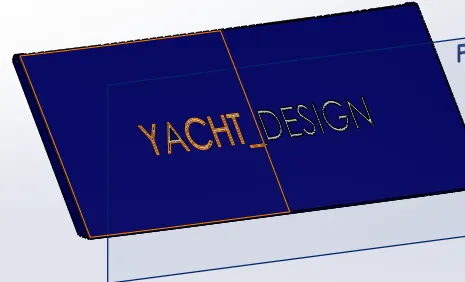
- hence modellinng of the Garage Door of the Yacht is performed as shown above.
- Different standard views of the Garage Door is given below:
Front View:
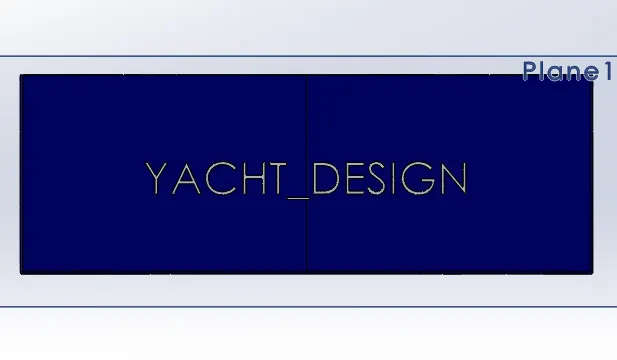
Side View:
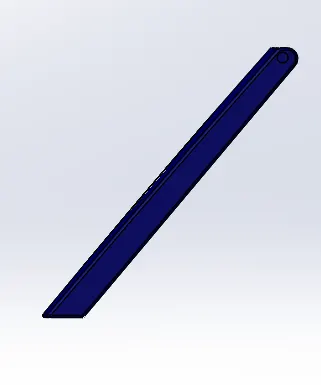
Top View:
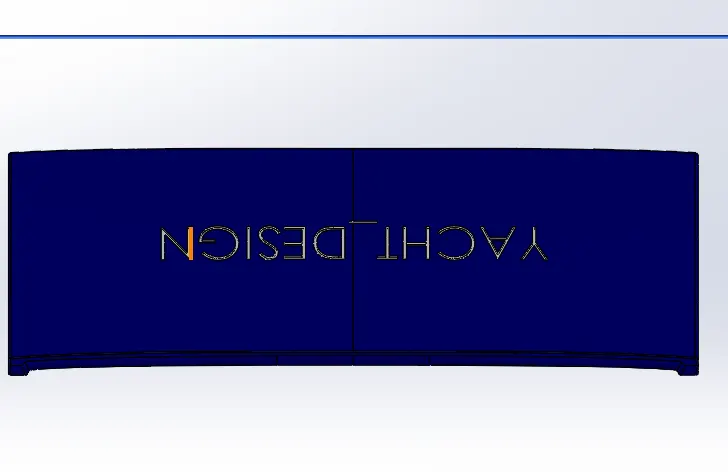
Isometric View:
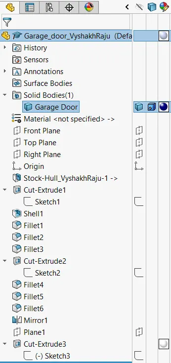
Model Tree:
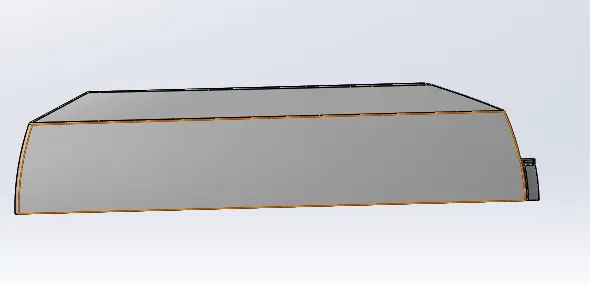
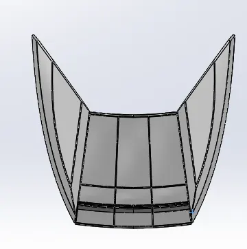
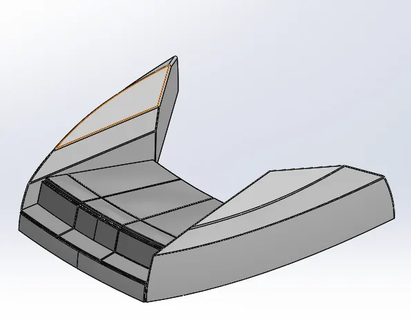
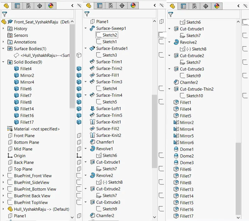
Front Seat:
Initially the blueprint setup model is opened and then saved as Front Seat Model.
Hull model is inserted as part and only the deck surface is inserted into the model.
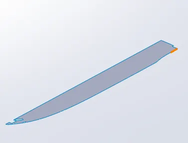
Seat profiles are sketched onto the deck surface and extruded:
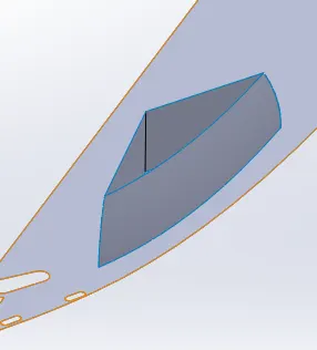
Similarly profiles of the seat areas are sketched and extruded
Surface fill option is used to create a solid body from the created surfaces:
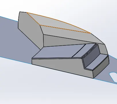
Bodies are mirrored seperately since seat portions are not a single body:
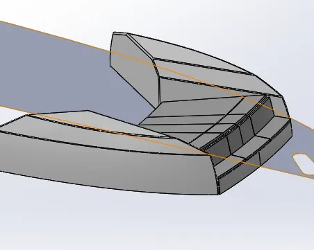
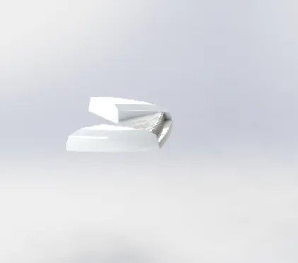
Dome option is used at the seat area to ressemble cushions
Fillets are provided at necessary edges:
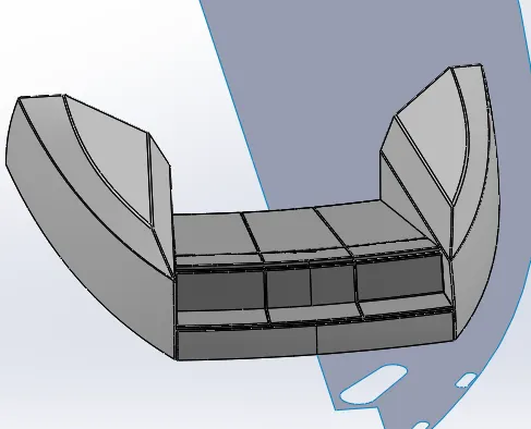
Appearances to the model is set using different colours.
Hence modelling of the front seat is finished.
Different standard views of the same are given below:
Front View:
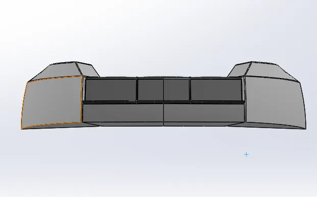
Side View:
Top View:
Isometric View:
Model Tree:
Middle Seat:
Initially the blueprint setup model is opened and then saved as Middle Seat Model.
Hull model is inserted as part and only the deck surface is inserted into the model.
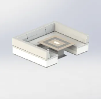
The seat body is sketched on deck surface and extruded out using extruded base option:
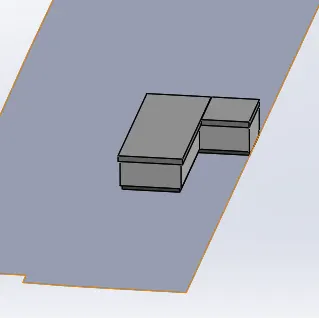
The back support area is then sketched and extruded and chamfered to give the slant profile:
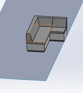
Necessary fillets are given and the seat body is mirrored:
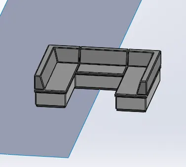
Next, stand body for the table top is created using sketch and extrude option:
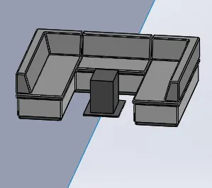
Similarly, table top body is also extruded and appearance is given to the top portion:
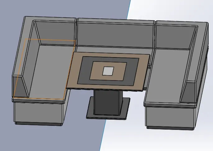
Hence finished modelling Middle Seat of the Yacht Model.
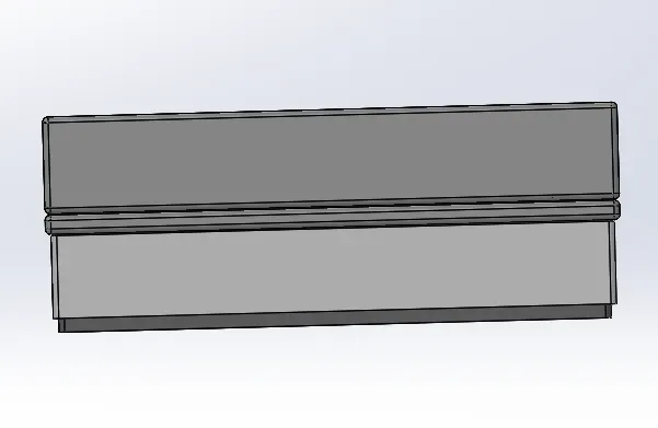
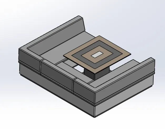
Different standard views of the middle seat model is shown below:
Back View:
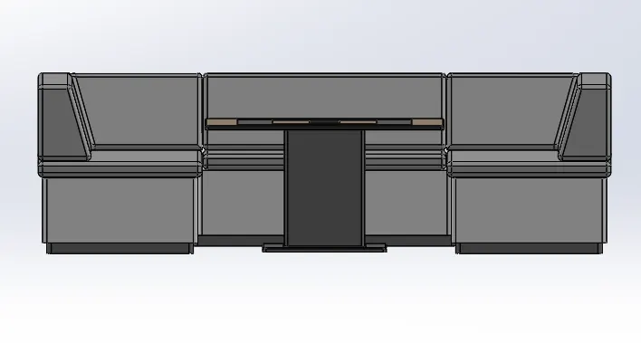
Side View:
Top View:
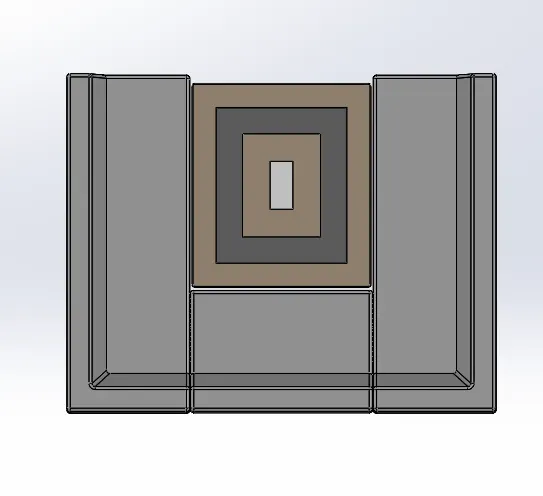
isometric View:
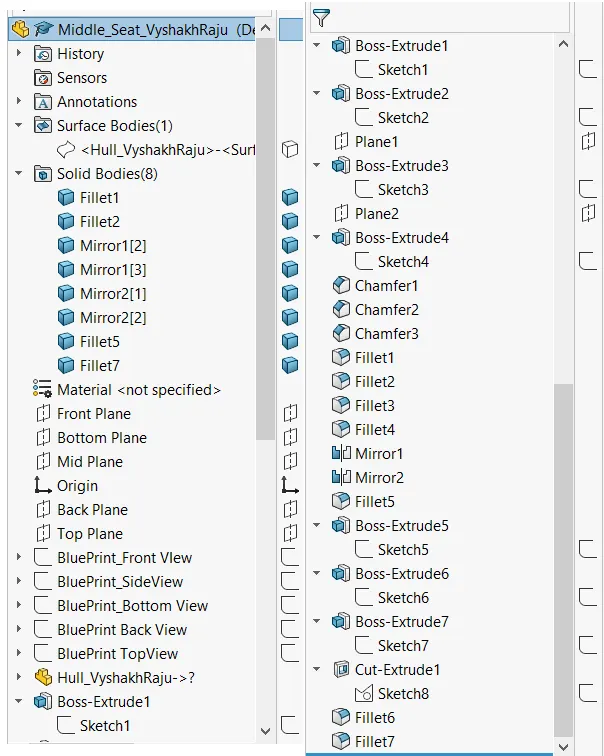
Model Tree:
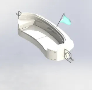
Rear Seat:
Initially the blueprint setup model is opened and then saved as Rear Seat Model.
Hull model is inserted as part and only the deck surface is inserted into the model.
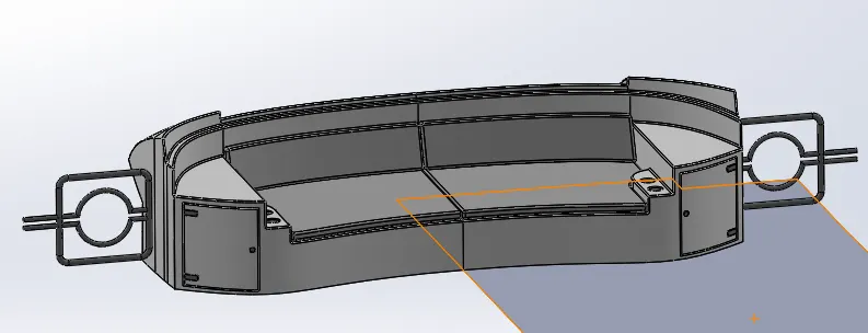
The rear seat outer profile is sketched and swept surface is created:
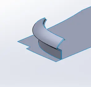
Inner surface is sketched and extruded to create a closed surface:
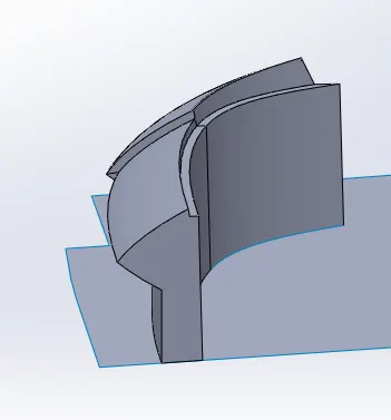
Sketches are made on the new surfaces to create the seat profile and is then extruded:
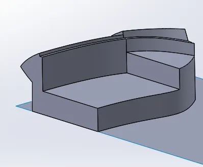
Seats are made by offsetting the surfaces and extrude option is used:
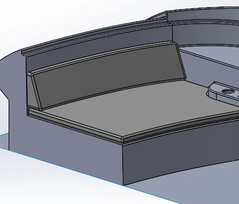
Gates are created by sketching profile and sweep option used to create the body:
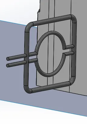
Extruded cut option is used to create a cut on the surface to ressemble the storage spaces on the seat body:
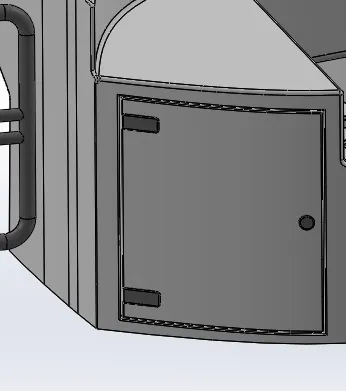
Mirror opotion is used to mirror Body, seats and the gates :
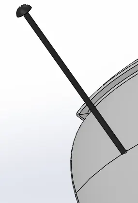
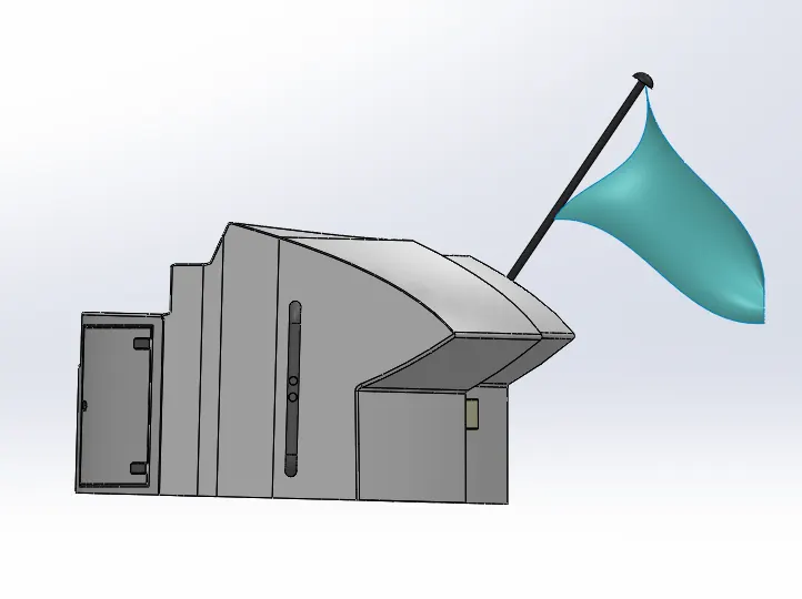
Sketch of flag post profile is made and is revolved to create the body:
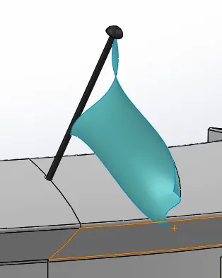
3D sketches are used to create the flag profile and lofted surface option is used to create the flag body:
Hence completed modelling the rear seat of the yacht model.
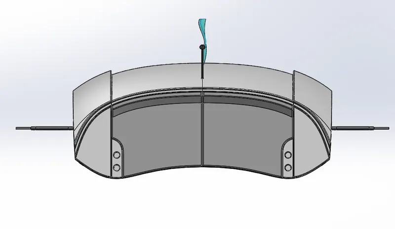
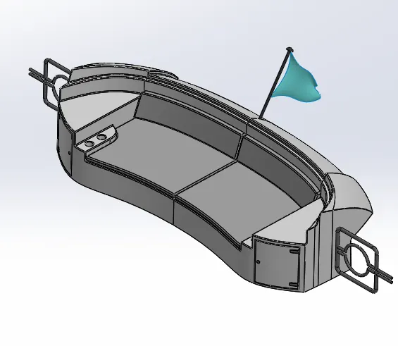
Different standard views of the Rear seat model is as shown below:
Front view:
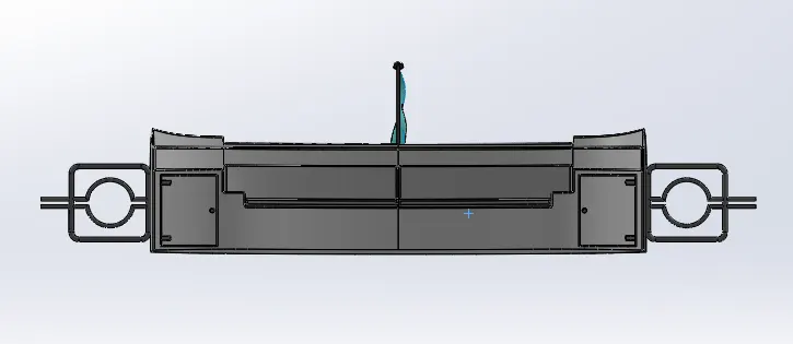
Side View:
Top View:
Isometric View:
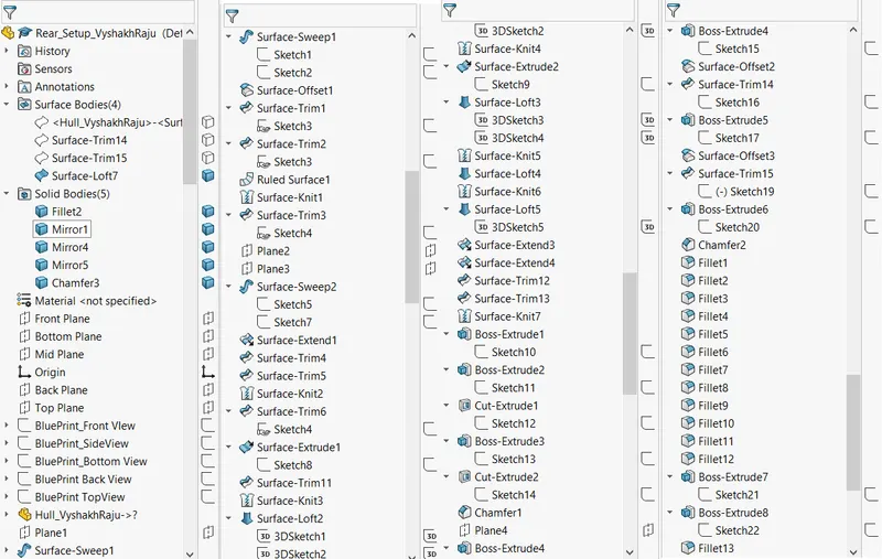
Model tree:
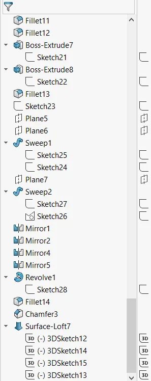
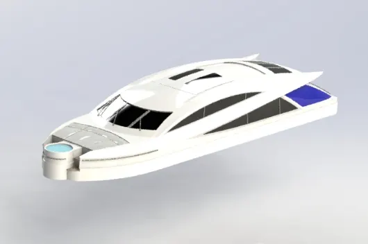
Superstructure:
- Initialliy the blueprint setup model is opened.
- Hull part is inserted inorder to use the deck surface as the reference to model the Superstructure:
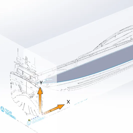
- Surface extrude option is used with help of profile sketches to make the base surface of the superstructure
- Sweep option is used to create the horizontal profiile
- Ruled surface is used to create the vertical tapered surface from the swept surface:
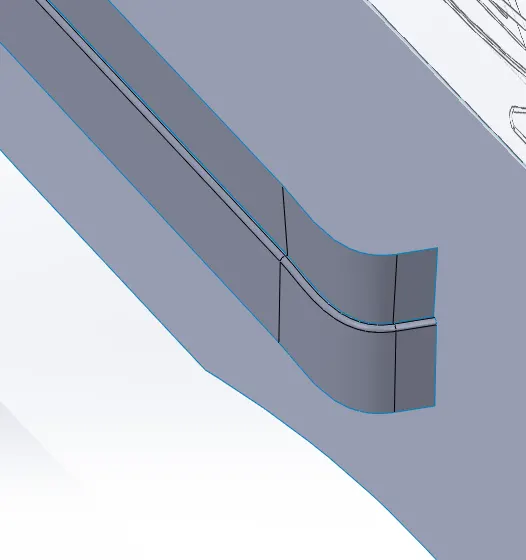
- Lofted surface option is used to create the top curved surface by using 3D sketches:
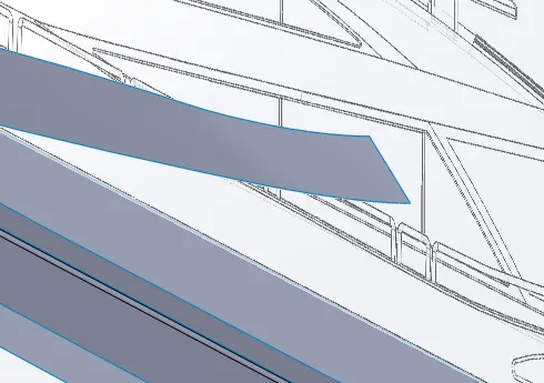
- Similarly lofted surface and extrude option is used to create additional surfaces
- Necessary trims are also performed using extruded cut option:
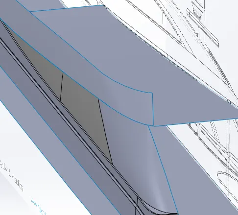
- Further modelling is performed using Lofted surface option, Ruled surface option and Extrude cut options:
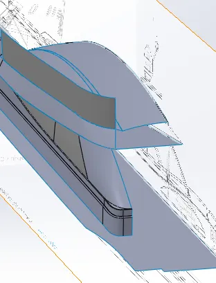
- Front part of the superstructure with stairs are also modelled using surface sweep and extrude options:
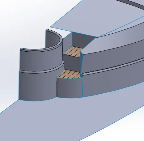
- Extra deck surface is trimmed to make the base of the superstructure:
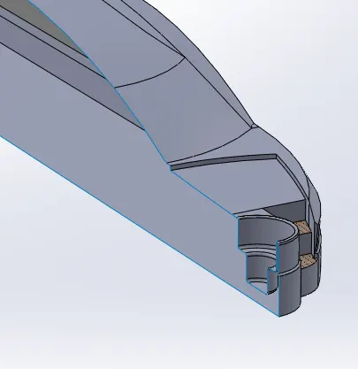
- Knit surface option is used to merge all the different surfaces together into one single surface body
- Finally form solid option under knit surface option is used to crearte a solid body from the created surfaces
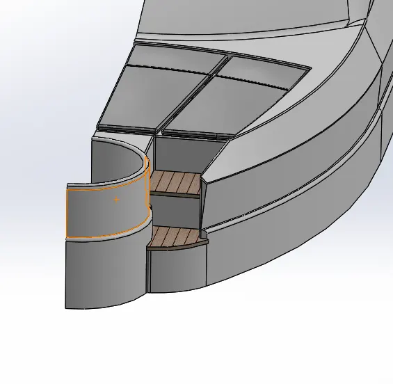
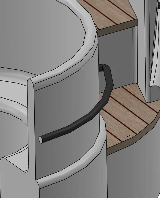
- Sweep option under the features tab is used to create the railings on the sides of the superstructure:
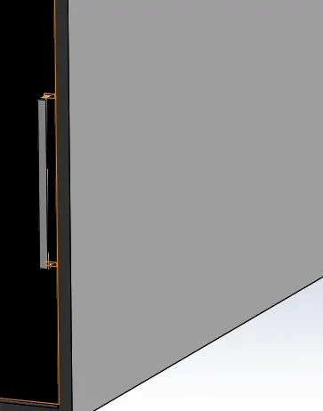
- Handle for the rear door frames are created from sketch using the extrude option:
- Mirror option is used to mirror the superstructure body, jacuzzi and the cushions at front:
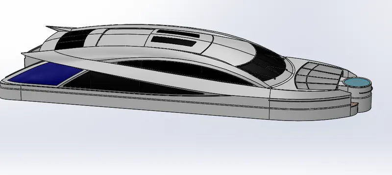
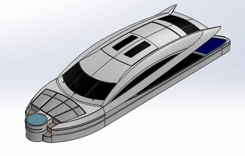
- hence modelling of the superstructure of the yacht is finished.
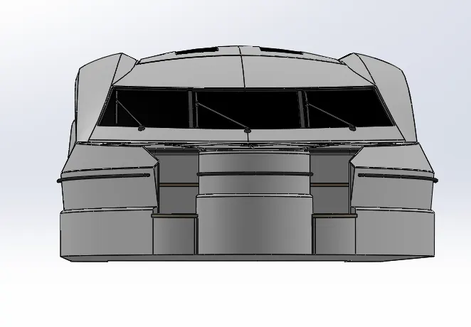
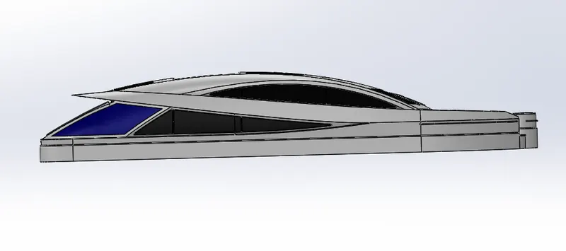
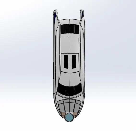
- Different standard views of the superstructure is as given below:
Front View:
Side View:
Top View:
Isometric View:
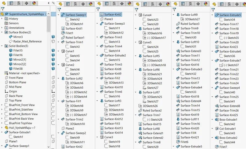
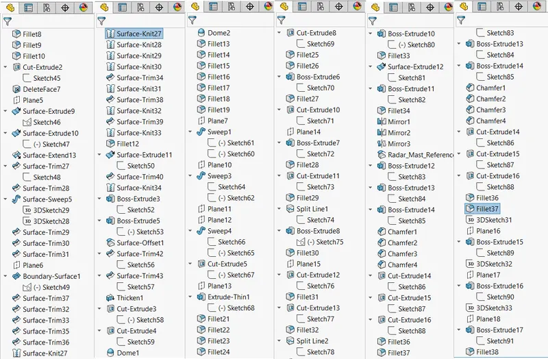
Model Tree:
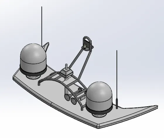
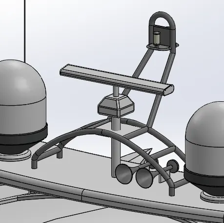
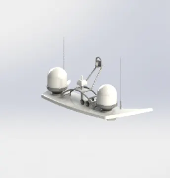
Radar Mast:
- Initially the blueprint setup model is opened.
- Reference surface from te superstructure part is inserted
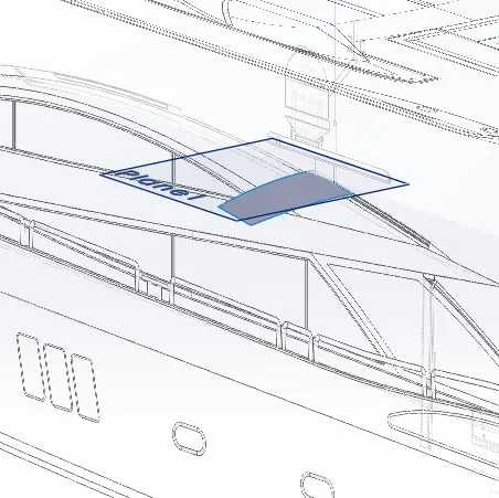
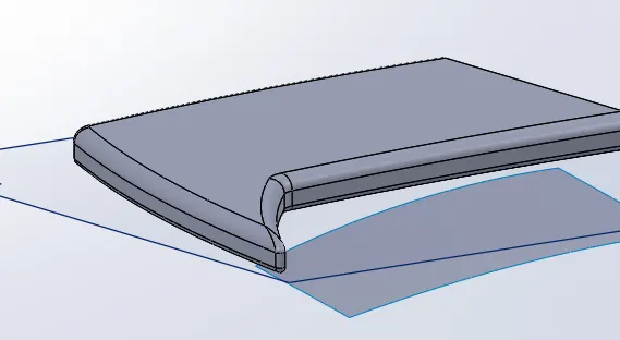
- Boss extrude feature is used to create the base surface of the radar mast
- fillets are also given to the edges:
- Revolved base option is used to create the radar body from the sketch profile:
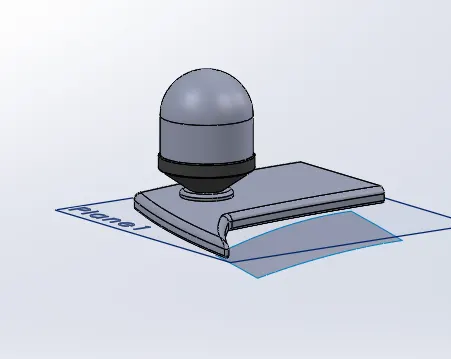
- Boss extrude option is used to create the antenna:
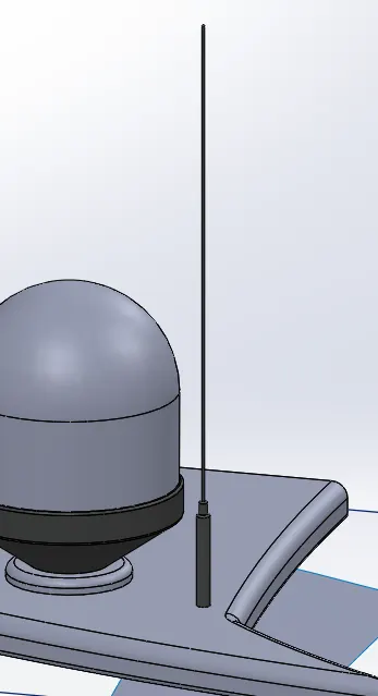
- Sweep option is used to create the profile of railings, then mirrored to form 2 sides:
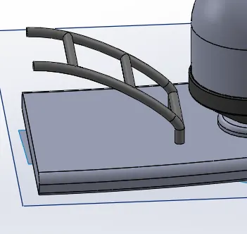
- Extruded base and sweep option is used to create the pole for lights:
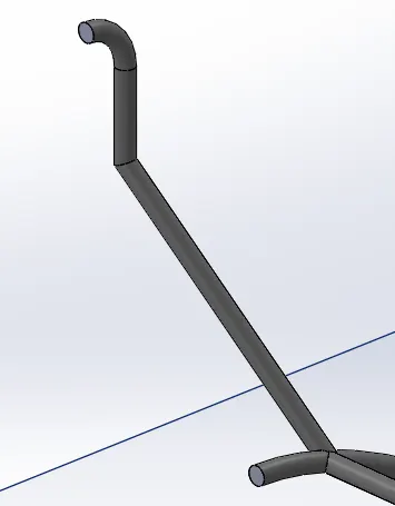
- Revolved base option is used to create the horn body from the sketch:
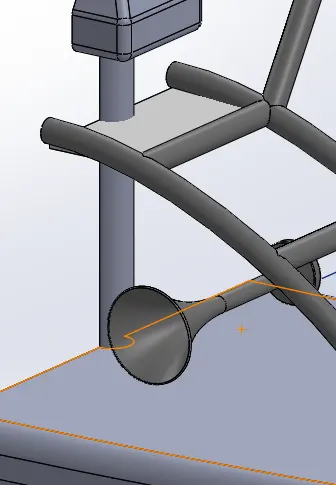
- second horn body is created by mirror feature using the first horn body.
- Mirror feature is used to mirror the radar body to make the full scale radar mast body:
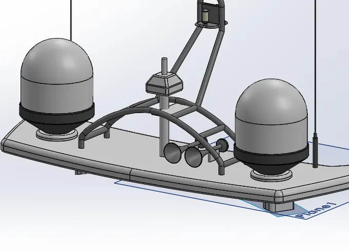
- Hence modelling of the radar mast is finished
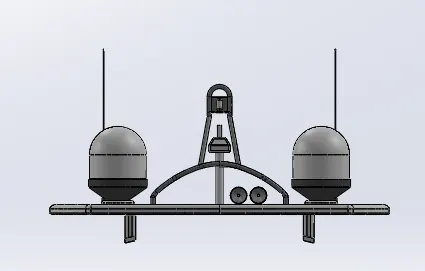
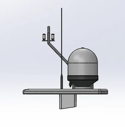
- Different standard views of the radar mast is shown below:
Front View:
Side View:
Top View:

Isometric View:
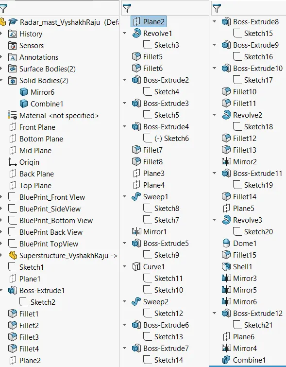
Model Tree:
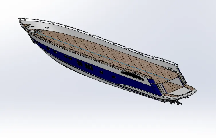
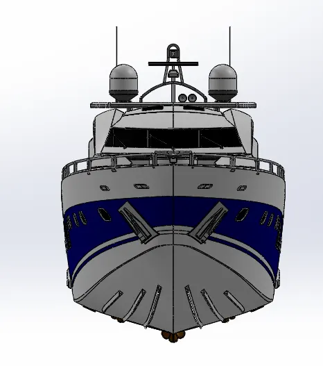
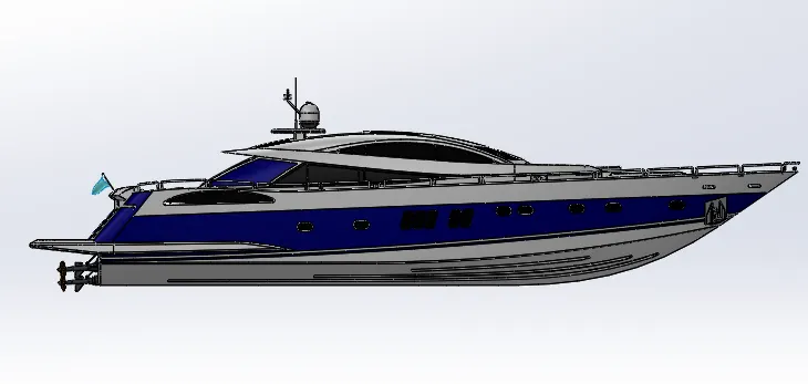
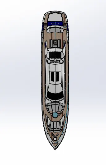
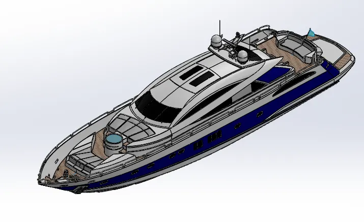
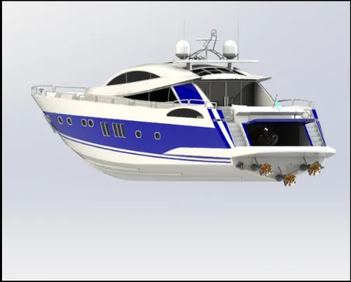
ASSEMBLY:
- Initially Hull part model is inserted to the assembly:
- Superstructure part model is then inserted and mated with midplane of the hull part:
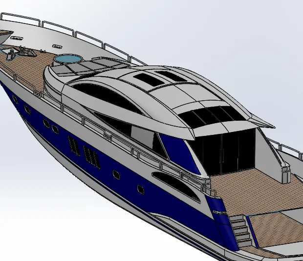
- Radar mast model is then inserted:
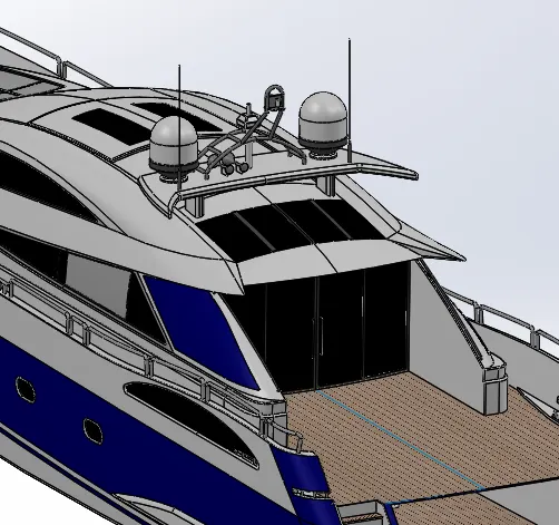
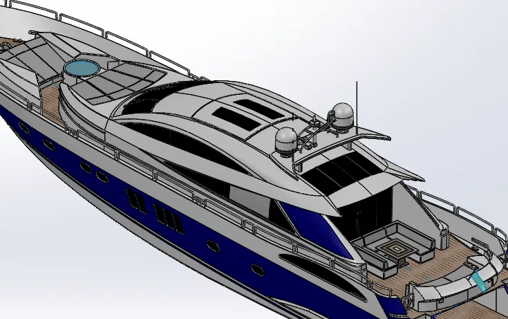
- Front, Middle & Rear seats are inserted.
- Mates option is used to position the rear seat in an exact distance from the edge of deck surface:
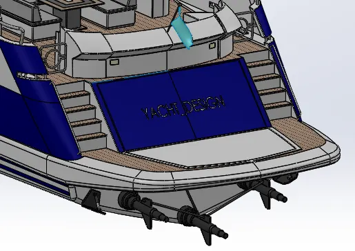
- Garage Door is then inserted and concentric mate is defined with the hull hinge part:
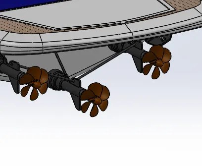
- Propellers are inserted and mates defined to keep it in place:
- Finally Radar is then inserted and concentric and coincident mate is defined with mast body:
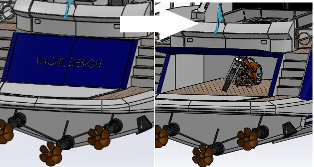
- American Chopper assembly model is inserted to position it inside the garage of the yacht:
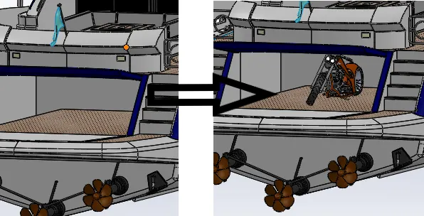
- Angle limit mate is given to the garage door to keep it constrained as a door.
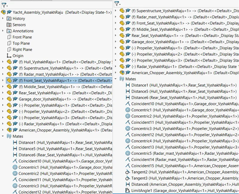
Assembly Feature Tree:
Front View:
Side View:
Top View:
Isometric View:
CONCLUSION:
- Modelling different parts of the Yacht is performed and the parts are assembled together inorder to get the full model of the Yacht.
- Parts of the Yacht modelled are as shown:
Propeller:
Hull:
Radar:
Front Seat:
Middle Seat:
Rear Seat:
Superstructure:
Radar Mast:
Assembled Yacht:
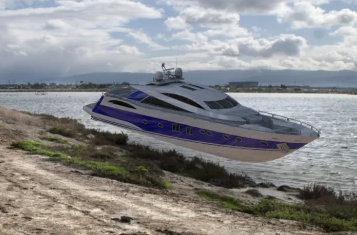
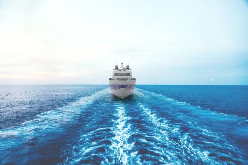
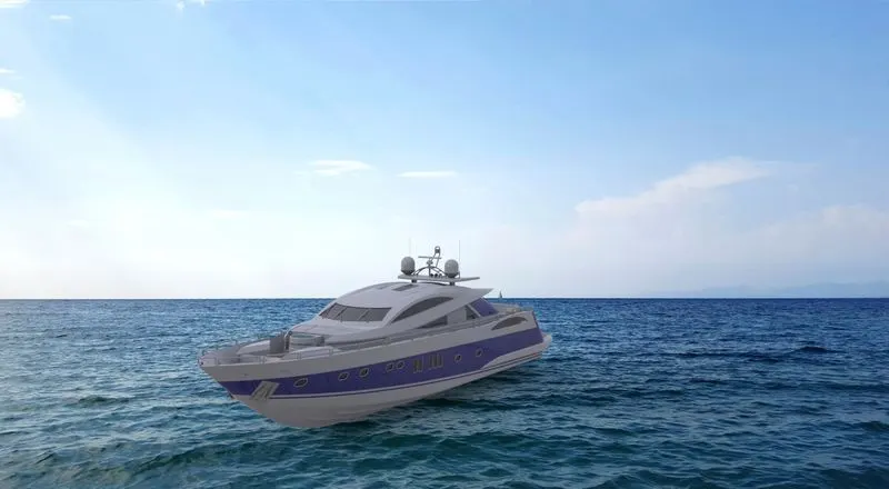
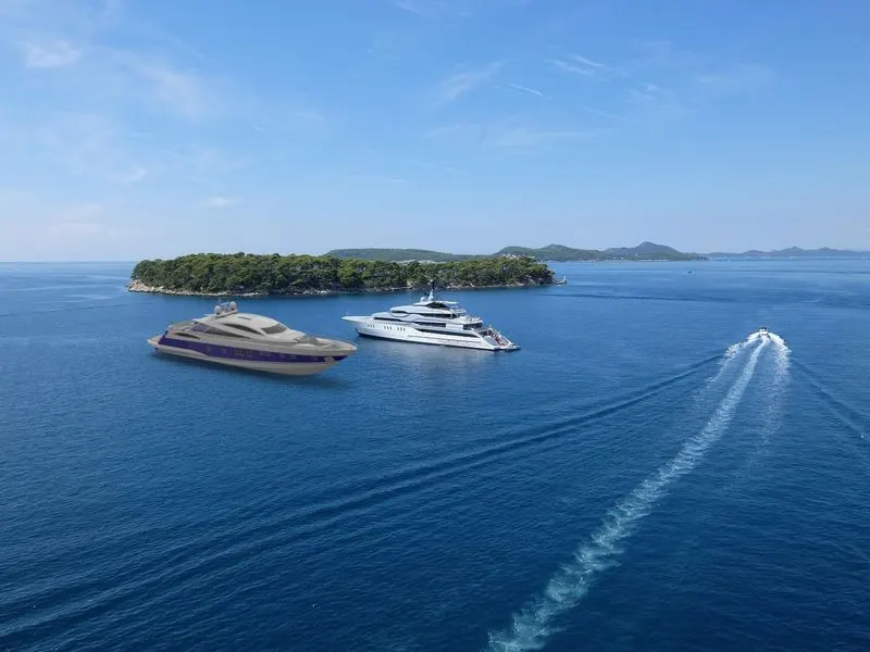
Rendered Images:
Link For Chopper Assembly:
Attaching link for chopper assembly files since it was not uploading through assets section with the yacht assembly file
https://drive.google.com/file/d/1nbzBUY1HTb5g2l0DK0fSxrif2Ie4HaLw/view?usp=sharing