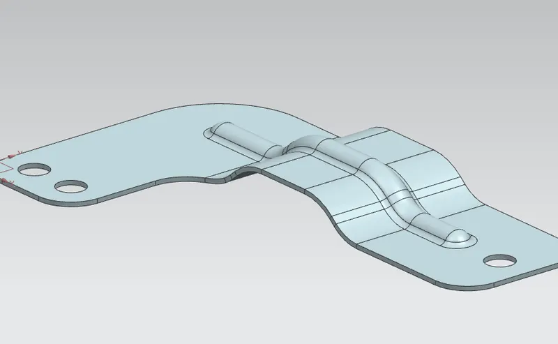
Advanced Sheet Metal Design Using NX Cad Challenge_6_Bracket
BRACKET DESIGN USING NX SHEET METAL APPLICATION
OBJECTIVE:
To design a Bracket with the specified dimensions and contour using NX CAD Sheet Metal Application.
INTRODUCTION:
This work is focused to design and create a Bracket as per specified dimensions and contour in the 2-D drawing.
DESIGN METHODOLOGY:
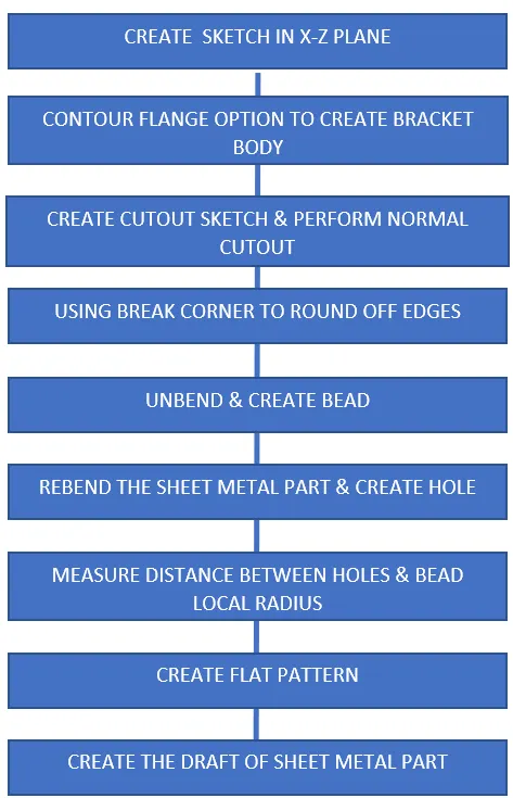
PROCEDURE:
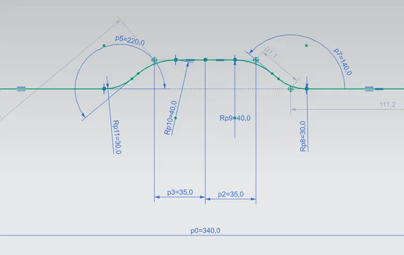
1) Create the sketch of the contour
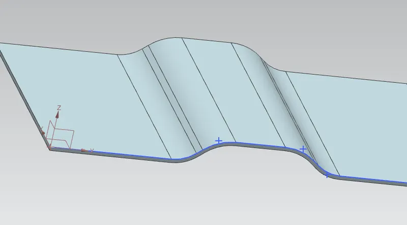
2) Using the Contour flange option wiht thickness of 3mm and width of 200mm
3) Creating sketch to cut out the bracket
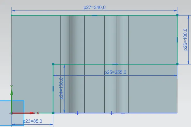
4) Using the Normal cut out option to cut out the non-required parts:
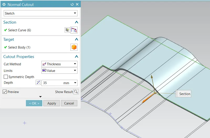
5) Using the break corner option to round off the edges with a radius of 25mm
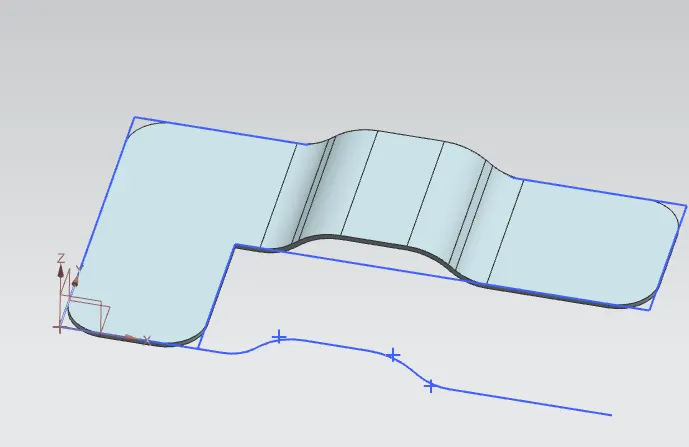
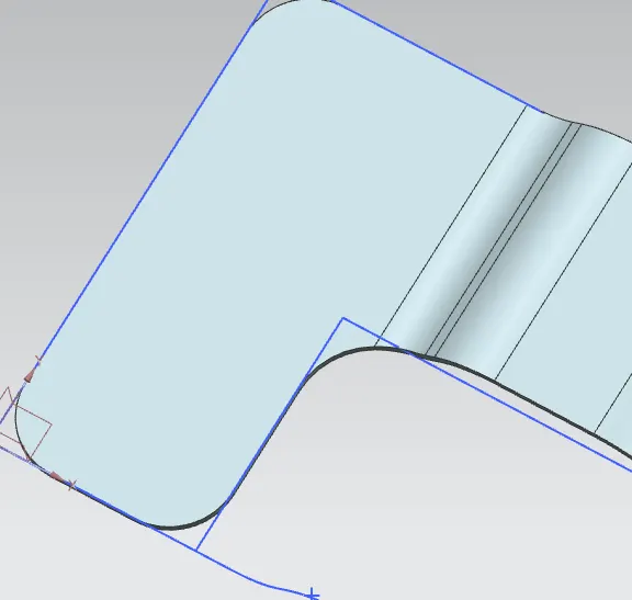
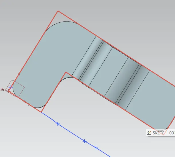
6) Creating sketch in the XY -Plane to assist in creating the Bead.
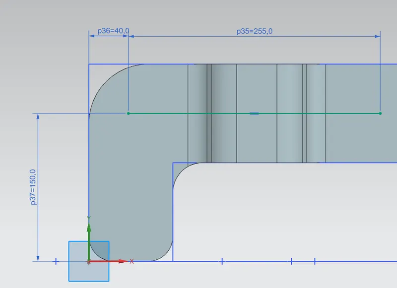
7) The created sheet metal part is unbend using the UNBEND option:
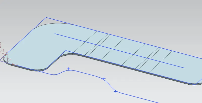
8) Bead is formed by selecting the created line as the curve with depth, radius and die radoius of 5mm.
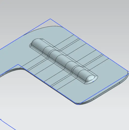
9) once Bead is formed, the sheet etal part is rebend to the original profile by using the REBEND option:
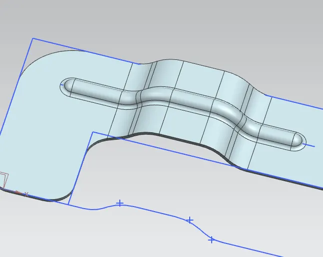
10) Creating a point on the Bracket at the specified location:
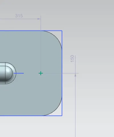
11) Creating hole using the HOLE option and with General type of hole with 20mm diameter.
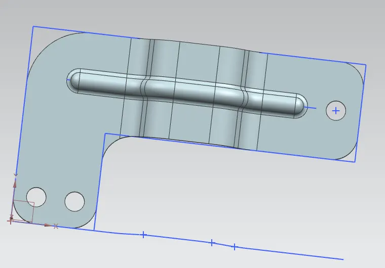
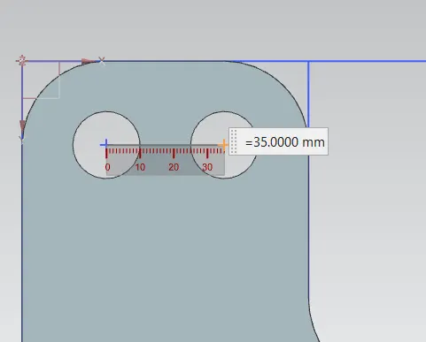
12) Measuring the distance between the holes
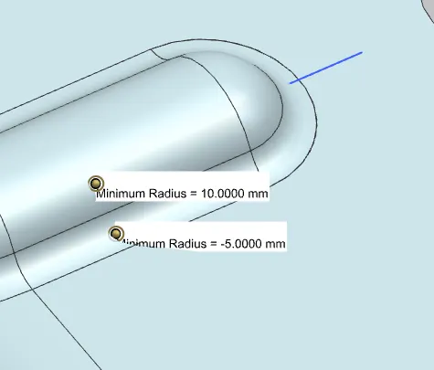
13) Measuring the local radius of the bead:
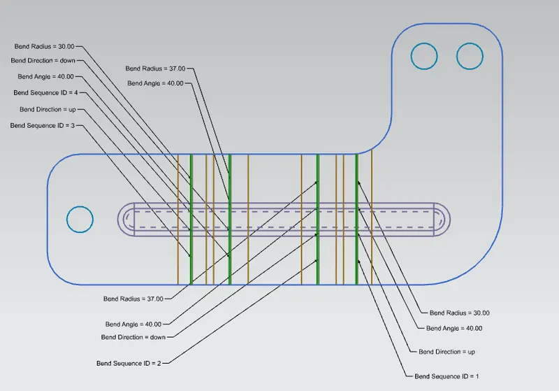
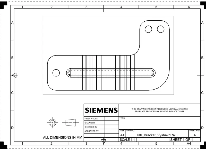
14) Creating Flat Pattern and drafting the Bracket:
CONCLUSION:
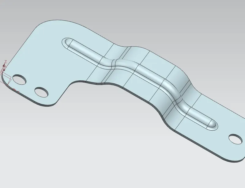
Hence the designing of a Bracket with reference to the given 2-D Drawing and Dimensions are completed.
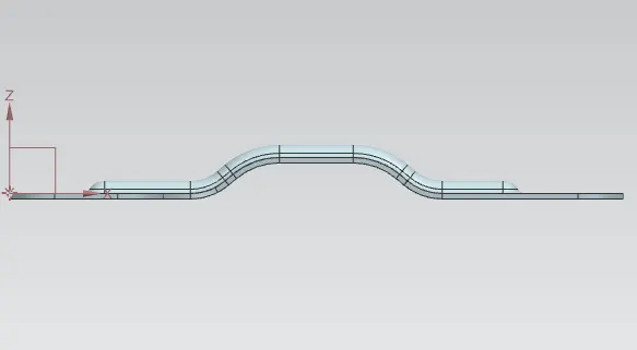
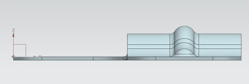
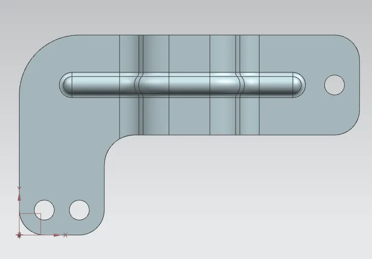
The different views of the Bracket is as follows:
Front View:
Right Side View:
Top View:
Isometric View: