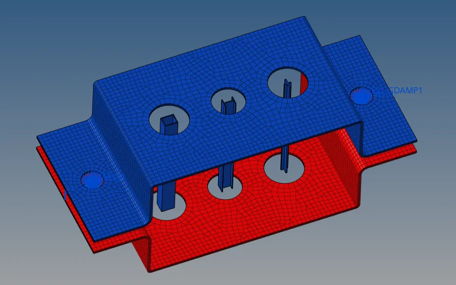
CREATING MIDSURFACE & 1-D Elements
AIM:
- To extract midsurface of a Bracket from the given geometry.
- To create 1-D Elements (BAR , ROD & BEAM Element) at specified locations
- To introduce mass on specified location and join the two parts using Spring Element.
MODELLING:
STEP 1:
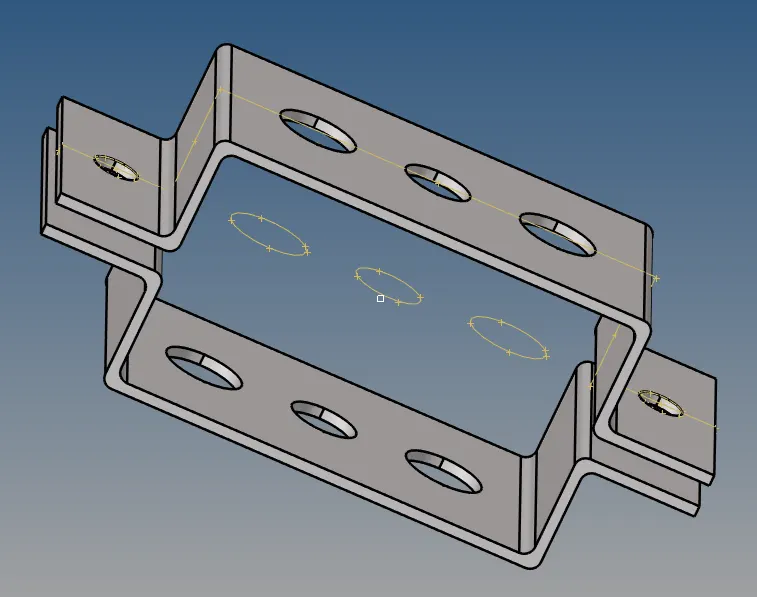
- The given geometry (IGS File) is imported using import geometry tool.
STEP 2:
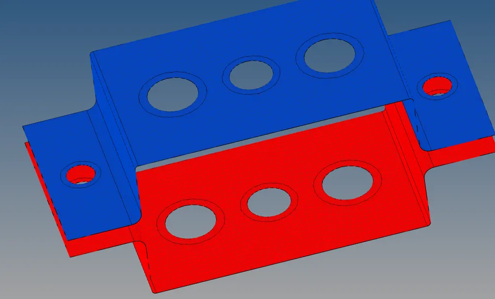
- Top part of the Bracket is displayed and other part is hidden. Midsurface tool is selected from the geometry tab
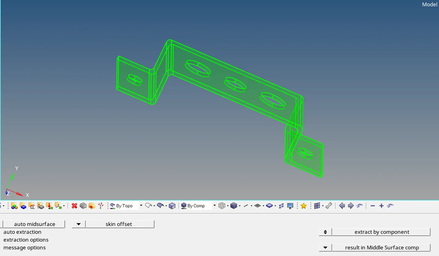
- Midsurface is generated for top half of the bracket by selecting skin offset extraction type since this type provided the best midsurface profile over the edges as compared to other extraction types.
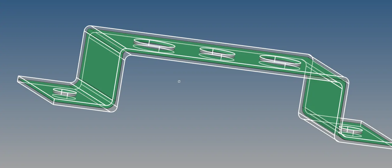
- Similarly bottom part midsurface of the bracket is also created.
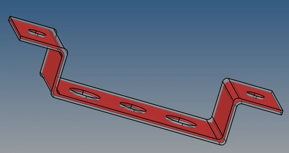
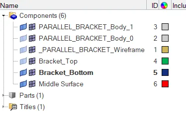
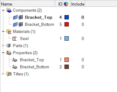
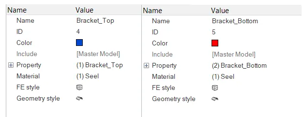
- Midsurface generated for the top is renamed as Bracket_Top. Another component is created named Bracket_Bottom to save the bottom mid surface.
- The midsurface for bottom is created seperately and then moved to newly created component(Bracket_Bottom) using organize tool.
- Components other than Bracket_Top & Bracket_Bottom is deleted.
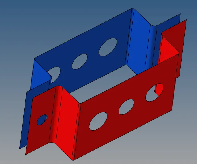
- Midsurface for the given Simple bracket is created successfully.
STEP 3:
- Washer split is created for the holes on the surfaces for creating a better mesh.
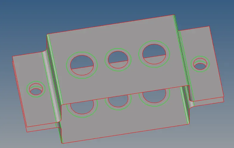
- Meshing of the both surfaces generated is done using automesh tool in 2-D Tab. Number of nodes along edges and holes on the profile are adjusted to get better mesh.
STEP 4:
- Material and property is defined for the bracket. Also thickness of Bracket is defined as 2.5 for both parts.
STEP 5:
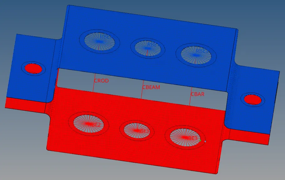
- RBE2 link (Cluster of elements) is created as per given conditions on both parts of the bracket using the rigid tool and selecting nodes where element is to be created.
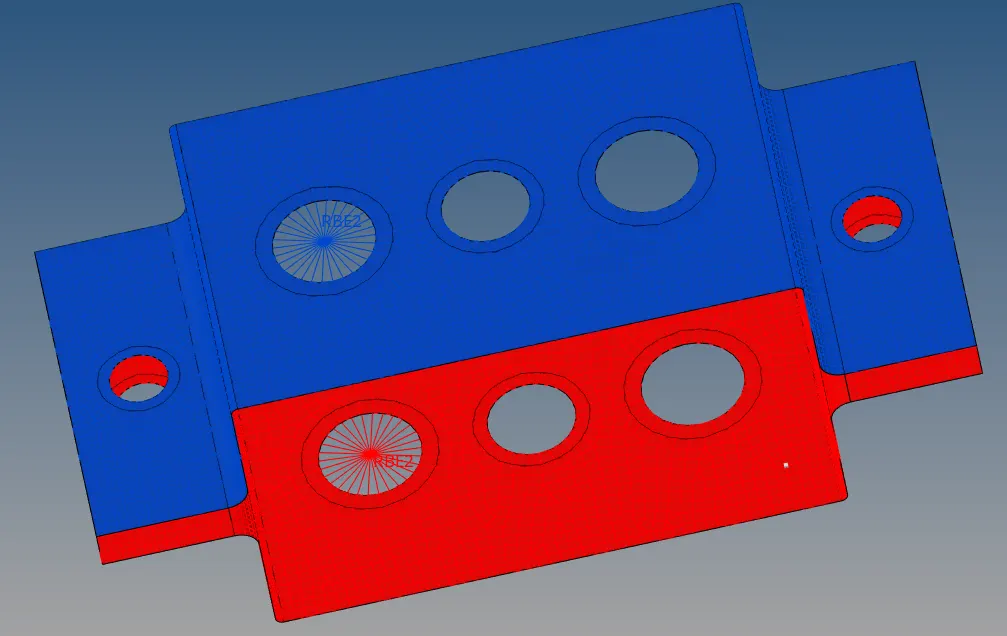
- As per given conditions, only translational dof is applied to the created RBE2 element.
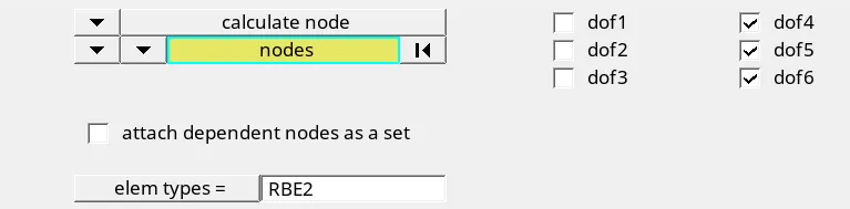
- Next, RBE3 elements are created as per conditions with specific dof conditions.
- ROD, BEAM & BAR elements are created using RBE2 and RBE3 elements created to obtain BOX, I & CROSS Section.
STEP 6:
- Hyperbeam tool is used to generate the required BOX, I & CROSS Section.
As per given conditions,
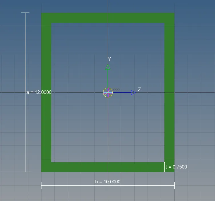
- BOX (Rod Element) is created using Hyperbeam tool and standard section type thinwalled box.
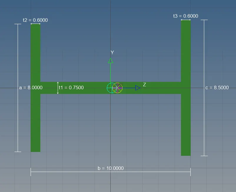
- I Section (Beam Element) is created using Hyperbeam tool and standard section type Standard I Section.
- CROSS Section (Bar Element) is created using Hyperbeam tool and standard section type CROSS.
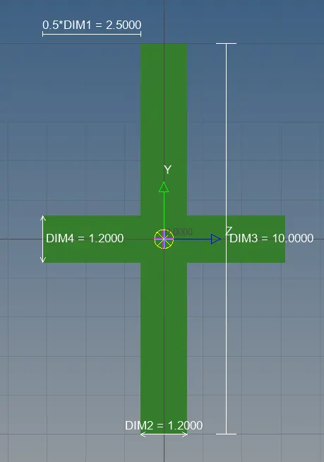
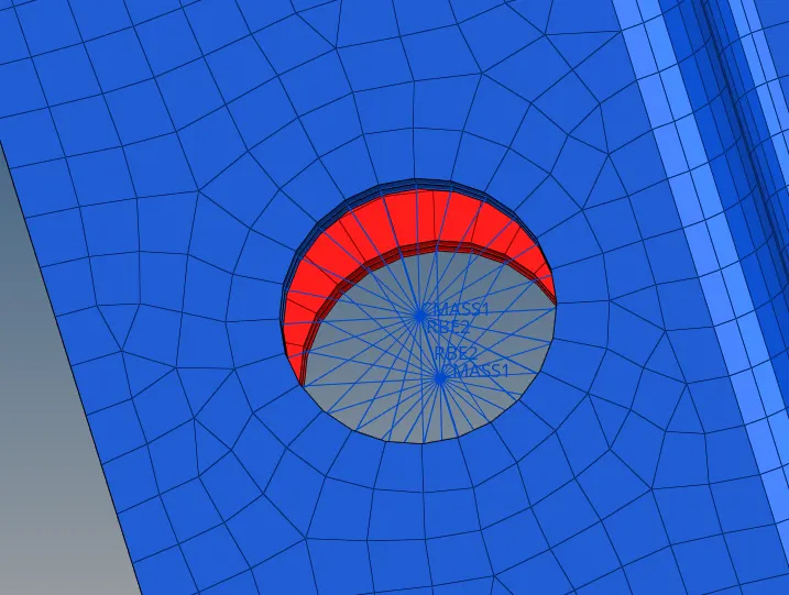
- RBE2 Link is made on the outer hole of the bracket on both sides and both bracket parts using rigids tool
- mass of magnitude 10 is introduced using masses tool in 1-D Tab. Mass element type selected is CMASS1.
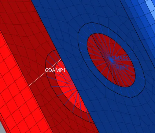
- Spring element is created by selecting nodes at the outer edge as per condition given using springs tool in 1-D Tab. Spring element type selected is CDAMP1.
STEP 7:
- Properties for each new elements introduced are created.
- Respective Card Image & Material for each element is selected.
Card Image:
- PROD for BOX, PBEAM for I-Section, PBAR for CROSS , PDAMP for Spring & PMASS for mass element is selected
- Steel material is selected for all the elements and surfaces.
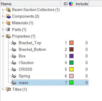
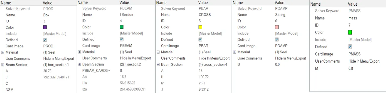
- Each new property created for the elements are updated using update option in Bar, Rod, Spring & Mass tools under 1-D tab
- Finally 1-D Detailed Elements Representation is selected to display the created Bar, Rod & Beam Elements
- 2-D Detailed Element Representation is selected to display 3-D representation of the Bracket Mid-Surface.
RESULT:
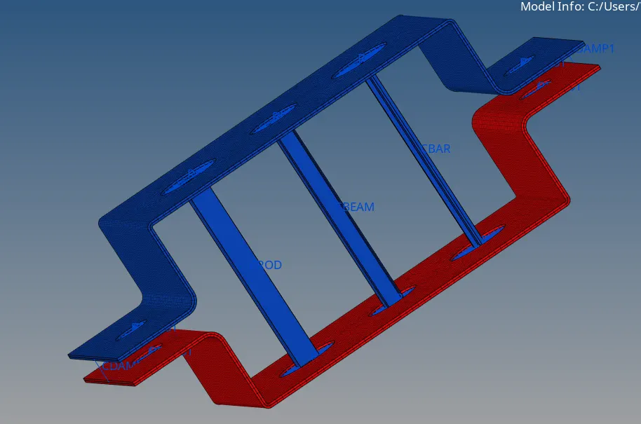
- Midsurface for the given Bracket was created and BOX, I-Section and CROSS sections are made, with mass on specified points and Bracket parts attached with Spring elements.