Assignment 2-RADIOSS Engine File Editing & 3D Meshing Challenge
OBJECTIVE :
- Check Material Property of the Rail component and Calculate the following:
- 1) speed of sound in steel rail.
- 2) time taken for a shock wave to travel from one end of the rail to the other.
- 3) time for sound to travel length of rail.
- Edit the engine file so that the stress wave can be monitored, moving from one end of the rail to the other during impact.
- Set the frequency of animation output to a time that will give 20 animation steps
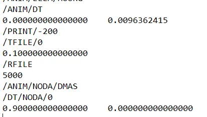
- Change /print -10.
-
3d meshing tetra mesh and hex mesh
- Repeat class examples and, maintain the quality.
- Target tet size=5mm,hex size=10mm,tet collapse=0.15.
Solution:
1) Check Material Property of the Rail component.
- Inorder to check the material property of the defined Rail Component, FIRST_RUN_0000.rad file is opened.
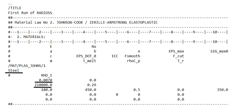
The file gives value of,
Youngs Modulus, E = 210000
Density, Rho = 0.0078
To Calculate:
1) Speed of sound in Steel Rail:
Speed of sound in solids,
Csolid = √( Youngs Modulus / Density of solid)
Csolid = √(210000/0.0078) = 5188.745 m/s
Therefore, Speed of sound in Steel Rail = 5188.745 mm/ms
2) time taken for a shock wave to travel from one end of the rail to the other:
For elemental time step, we have :
∆te = L / Csolid
Given, Length of rail = 1000mm
Speed of sound, Csolid = 5188.745mm/ms
Time Step, ∆te = 1000 / 5188.745 = 0.1927248 ms
Therefore, time taken for a shock wave to travel from one end of the rail to the other = 0.19272ms
3) time for sound to travel length of rail:
Time taken for sound to travel length of rail = time taken for shock wave to travel length of rail
Therefore, time for sound to travel length of rail = 0.19272ms
2)Edit the engine file so that the stress wave can be monitored, moving from one end of the rail to the other during impact.
Given Engine File:
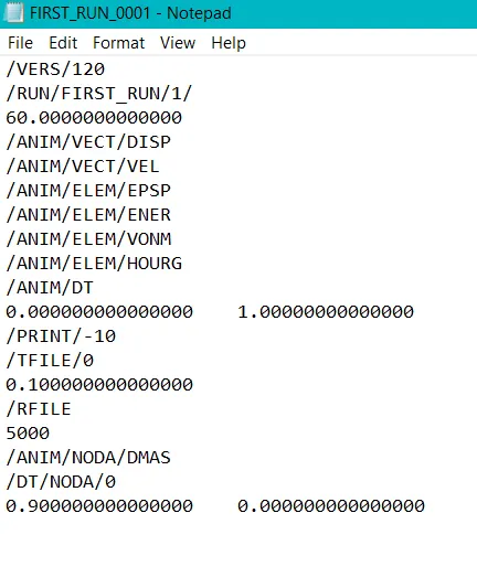
In the default engine file, the termination time is set as 60ms.
Editing the default run time to time taken for the sound to travel the length of the rail = 0.1927248ms
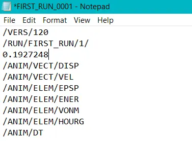
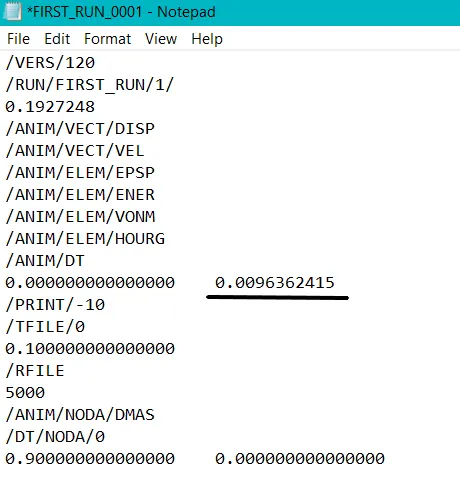
3) Set the frequency of animation output to a time that will give 20 animation steps
We have Total time step, ∆te = 0.1927248 ms
Inorder to have 20 animation steps, total time step should be divided by 20.
Therefore, Frequency = 0.1927248/20 = 0.009636ms
Editing the default frequency in the engine file:
4) Change /print -10:
Value of /Print - 10 is changed to /Print/ - 200
5) 3d meshing tetra mesh and hex mesh:
Quality Criteria :
- Target tet size=5mm,hex size=10mm,tet collapse=0.15.
Model 1 - Arm Bracket - Hex Meshing:
Procedure:
- Import:
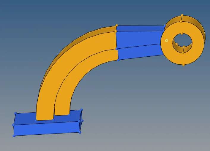
- Thie given Arm Bracket model is imported using import geometry option.
- Meshing:
- Starting from the base component, 2-D elements are created using automesh option uder 2-D tab with hex size of 10 mm.
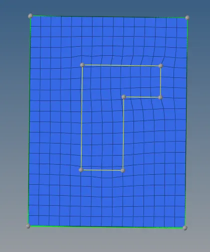
- To obtain 3-D hex mesh, elem offset option under 3-D tab is used.
- The 2-D elements created are selected, thickness, no. of layers and along geometry is selcted under solid layers option.
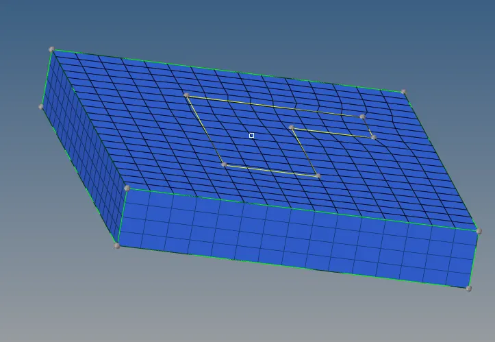
- To mesh the arm_curve part, spin option under 3-D tab is used after masking the hex8 elements created.
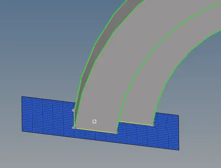
- Spin elems option is selected, with angle = 90deg and on spin = 20 (layers) and 3-D elements are created.
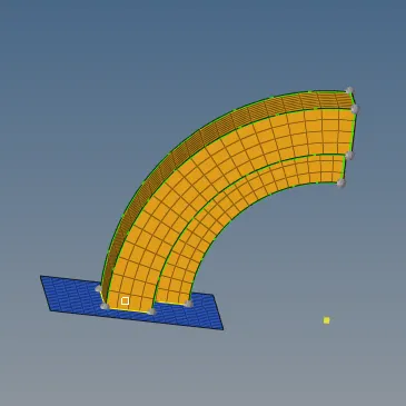
- To mesh on the arm_Straight part, which is having a taper, linear solids option under 3-D tab is used.
- To use linear solids, 2-D elements should be present at the start face of the part. Hence faces option under tools tab is used.
- The 3-D elements on the arm_curve is selected and face is created.
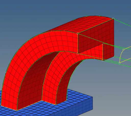
- In case of linear solids option, there should be start elements as well as destination elements. So destination elements are created using automesh option under 2-D tab with node orientation matching with the start elements.
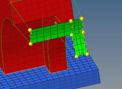
- Creating the 3-D mesh with linear solids option.
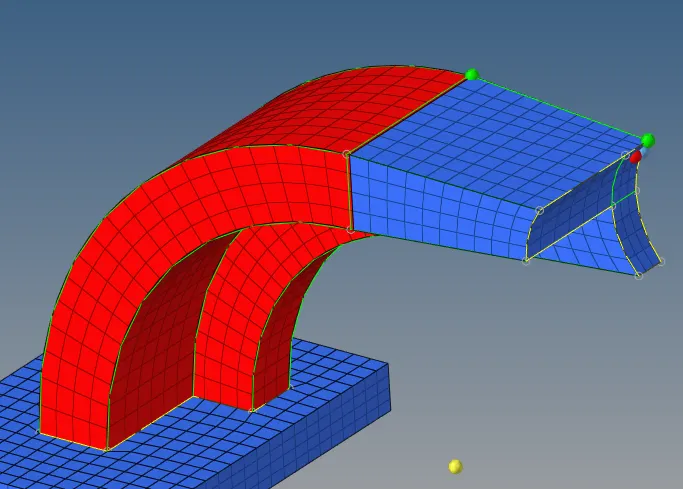
- The remaining part to be mesged is the boss.
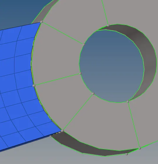
- Meshing the top surface with 2-D elements using automesh option.
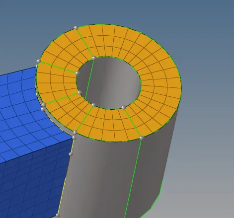
- After 2-D elements are created, a node which is normal to the present element nodes are created on the bottom surface of the boss.
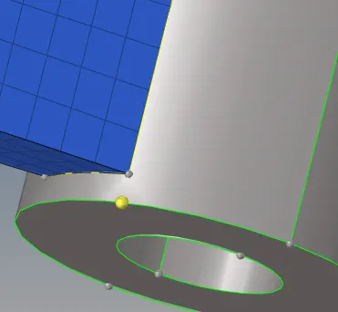
- Now using solid map option under 3-D tab to obtain 3-D hex mesh on the boss.
- The elemenst created by solid map is stored under new collector(solid map) which is moved to boss using organize option.
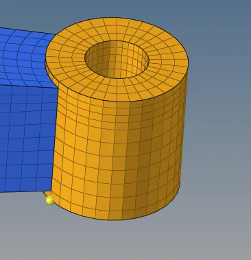
Conclusion:
Hence 3-D hexa meshing of the arm bracket is carried out by using various options (elem offset, Linear solid, Solid Map, Spin)under 3-D tab
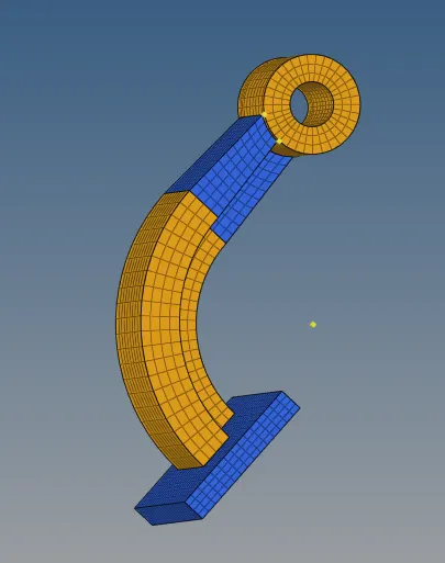
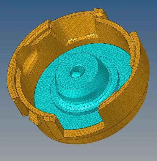
Model 2 - Housing - Tetra Meshing:
Procedure:
- Import:
- Thie given Housing model is imported using import geometry option.
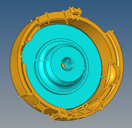
- Meshing:
- 2 parts of the Housing are meshed seperately. Initially the surfaces are meshed using automesh option under the 2-D tab.
- Element size is set as 5mm and mesh type as trias.
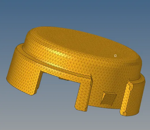
- To convert the created 2-D tria elements to tetra mesh, tetra mesh option under 3-D tab is used.
- The elements are selected and tetramesh parameters (min. tet size and tet collapse) are defined and meshed.
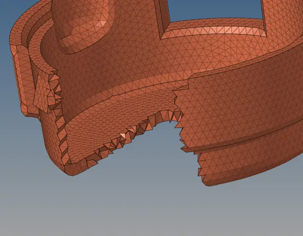
- Some of the elements are masked to check whether tetra elemenrs are created throughout the part.
- The created tetramesh elements is saved under different collector which is moved to the parent collector using organize option.
- Hence the cover part of the housing is meshed using tetramesh option.
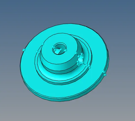
- Now to mesh the hub part, volume tetra option under tetramesh tool is used.
- Under volume tetra, 2-D type, 3-D type, element size is defined. Also the surfs is selected.

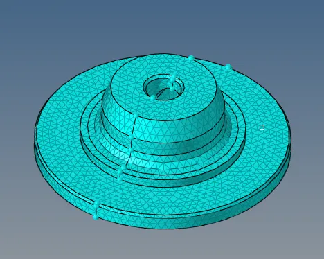
- Hence the hub part of the housing is also meshed using volume mesh option and mesh is obtained as shown above
- Tet collapse check is also used to check whether all the elements fall under the given quality criteria checked using check elems option
Conclusion:
- Given housing model is meshed using 2 different 3-D meshing techniques , tetramesh & Volume tetra and the elements are within the given tet collapse criteria