Simulink Model of Doorbell and Fan using Thermistor
Aim:
1. Making a Simulink model of Doorbell using Solenoid Block.
2. Making a Simulink model using a Thermistor to sense the temperature of a Heater & turn ON or turn OFF the Fan.
Proceedure:
Simulink model of Doorbell using Solenoid Block
1.To create a doorbell, we will first provide the Signal Builder. The doorbell will produce an output after every 2 sec. So for 10 sec, we will provide the signal.
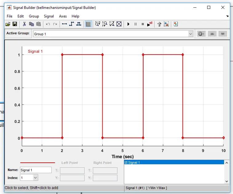
For first 2 seconds there is no signal, for the next 2 seconds there is an input. This goes on for 10 secconds.
2. Battery is providede as a power source. The input from the signal builder will reach the switch.
3. When the switch gets the signal, the plunger will move.
4. A solenoid block is connected in the circuit, that will move the plunger.
5. For plunger Ideal Translational Motion Sensor is used.
6. Before signal is sent to switch, it is converted using Simulink to PS converter block.
7. Between the scope block and Ideal Translational Motion Sensor, PS to Simulink converter block is used.
8. Mechanical Translational and Electrical Reference is provided, and to get the result we use Solver Configuration block.
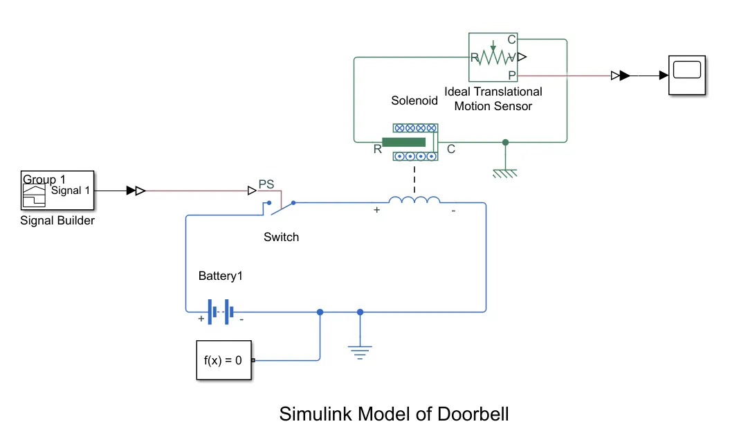
Fig: Simulink Model for Doorbell
Simulink model to turn ON and OFF the Fan
1. Varying temperature over a time is given in the signal builder block.
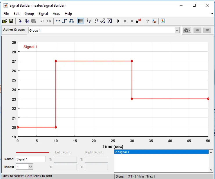
For 0 to 10 second signal is set at 20, for 10 to 30 second signal is set at 27 and for 30 to 50 second, signal is set at 23.
2. The signal is a temperature, to take that as a temperature, we use Controlled Temperature Source block.
3. Controlled Temperature Source block is connected to thermistor. A resistor is connected in series with the thermistor block. Voltage sensor is connected to calculate the voltage across resistor.
4. We provide battery as a power source. To check the treshold voltage we use 25 degree as temperature in seperate signal builder.
5. The result is displayed in the Display block connected to V end of voltage sensor. The result comes out to be 5.711e-22 V. In the conditional switch block, we provide this value.
6. Using two constant, we input the value as 1 if condition is matched and 0 if condition is not matched.
7. Using display block we see the final result if fan is switched on or not. We can see the graph for 50 second time using Scope block
8. We provide electrical and thermal reference. A solver configuration block is also used.
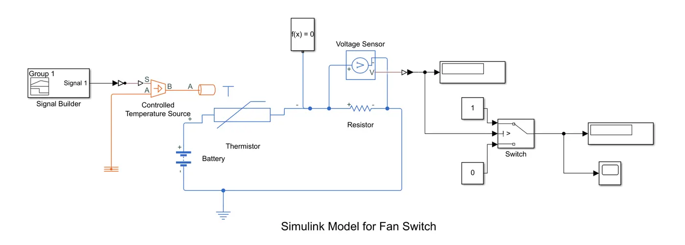 Fig: Simulink Model to turn ON and OFF the switch
Result:
1. For Doorbell, the result is as follow:
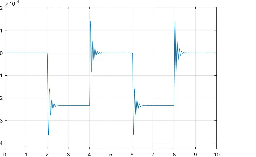
In the above figure, we can see that after every 2 second when the switch is connected. For first 2 second the output is on 0. Between 2 and 4 second there is an output as plunger moves. Again between 4 to 6 second and 8 to 10 second there is no output as there is no input in the signal builder block. Between 6 to 8 second we see an output as plunger moves.
2. For switching ON and OFF the fan using Thermistor the result is as follow:
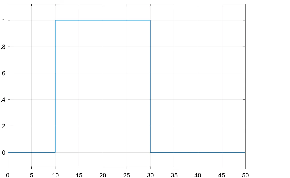
In the above figure, we see that between 10 and 30 second the temperature is beyond 25 degree Celcius. and we see the output. Between 0 to 10 second the temperature is below 25 degree celcius as a result it does not have the voltage to or beyond treshold point, as a result it does not produce any result. Between 10 and 30 second there is an output as the voltage is beyond treshold point. For the next 20 second cycle the temperature is again below 25 degree celcius and as a result the switch is turned off as the voltage is below treshold point.
Conclusion:
Created a Simulink model of Doorbell using Solenoid Block. Also created the simulink model to switch ON and OFF the fan using thermistor.