Connection of Rear Door
Connection of Rear Door
Aim: Assigning suitable Connectors to Rear Door model using Nastran deck on ANSA.
Connectors:
Connectors are ANSA entities, used to connect two or more sub-assemblies or parts together. Another major importance assigning connectors is that it provides the necessary constraints to the region. This is an important step needed to be done before we proceed for analysis. Usually connectors are not used for individual part, with the exception being nut and bolt region. It is used to connect sub-assemblies. The different type of connectors used in ANSA are,
1. Bolting: Various assemblies and sub-assemblies are connected by using nut, bolts and washer. To begin with, RBE 2 element are primarily used in areas for nut and bolt connection. To do this, various methods are used. RBE 2 is used for this purpose.
RBE 2: Used for connection of nut and bolts. Various method, depending on the part and element we deploy RBE 2 connection. It can be done directly by selecting the perimeter of bolting region or by providing zone cut to showcase and constrain washer region. RBE 2 is further categorized as:
a. Cluster (Many Node) RBE 2: It is used for constraining the local region of bolting.
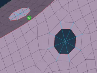
Fig: Cluster RBE 2 connection
b. Two Node RBE 2: It is used to connect two associated RBE 2 connection, which in turn constrain the rotary movement in almost every cases.
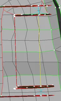
Fig: Two Node RBE 2 connection
2. Welding: Welding is one of the major connecting method used in automotive domain. As a result sub-assemblies connected by welding need to be defined before analysis. Following are the ways mostly used to define welding:
a. Overlap Shell: It is used when two parts are parallel to each other.
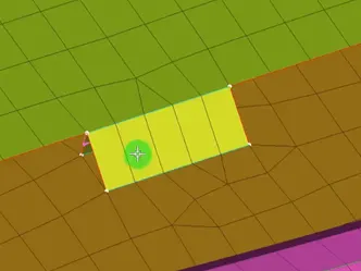
Fig: Overlap Shell
b. Y Joint Shell: It is used when two parts are perpendicular to each other.
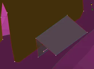
Fig: Y Joint Shell
c. Spot weld: It is used to define when two parts are spot welded.
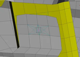
Fig: Spot Weld
3. Bushing: Car bushings are small rubber type suspension components that are used to isolate vibration, provide cushioning, and reduce friction between metal parts in the vehicle. RBE 3 is used for this purpose. RBE 3 is used in place where constraining of element is not done completely. This is done intentionally in areas where there are bushing, in order to provide definition, that the part somewhat has provision will have minimal movement to provide the cushioning effect.
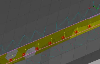
Fig: Bushing
Procedure:
- First we will open the file. The given file is in .nas format, as a result we will use input option to import the model. The given model is Rear Door which has critical connection such as window to railing mechanism, latch, hinges, door handles and window connection to the frame.
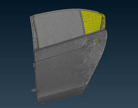
Fig: Rear Door Meshed Model
- We will start with latches and hinges mechanism. Major connectors used for the connection are bolting, as a result we will opt for RBE 2. For simple interconnected bolting we will use simple bolting and define the washer element by opting one element surrounding the perimeter.
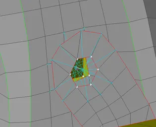
Fig: Connection on Bolt area
- For latches we will use combination of Cluster RBE 2 and Two Node RBE 2. First we will connect associated hole with Cluster RBE 2 connection at the top and the bottom. Once this is done, we will connect the top connection and bottom connection using Two Node RBE 2, which showcase the relation between them. While constraining we will opt for 5 Degree of Freedom in this case, which define the rotary movement on Z axis while opening the door is not constrained. We will do this with both the latches.
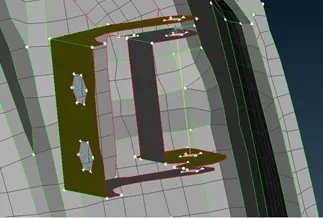
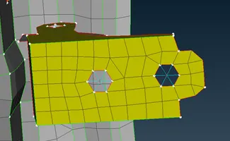
Fig: Connection on hinges Fig Connection on latches
- Now we will connect the window to the railing mechanism. We will isolate them, and by using MV Free command we will extend the railing mechanism element to the window
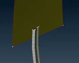
Fig: Extended Rail
Once done, we will improve the mesh flow first and then we will use RBE 2 connection to connect the window and mechanism. The element that are about nearly parallel and closer will be selected on the railing as well as on the window, and then we will connect them.
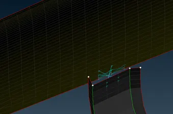
Fig: Connected Rail and Window
- We then shift our attention to door handles, here we constrain both the end of the door handle using Cluster RBE 2, and then we will connect both the connection using Two Node RBE 2. It will be followed by assigning mass to the Two Node RBE 2. It is done by first taking a COG point on the line and define them, then by using CM1 command we assign the mass of 100 gram. The value will be put in ton which is equivalent to 0.0001 tonnes.
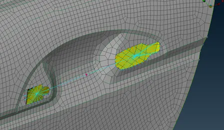
Fig: Connection at Door Handle
- For bushing of the window we will create a Curve and define them using Curve command. We will assign different Macros areas necessary with different Part ID.
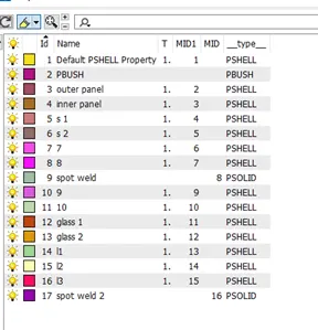
Fig: Properties ID for Bushing and Spot Welding
We will treat window as P1 and frame as P2. Using Connection Manager we will select this two and input D as 10. Choosing RBE 3 CBUSH RBE 3, we will assign the values and for PBUSH ID we will input the new ID.
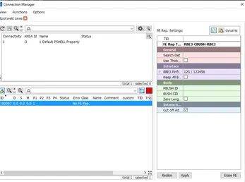
Fig: Connection manager for Bushing
At the bottom, bushing will be done both the side and for rest of the side one side is enough. We will prefer outer side for rest of the side. The connections are in its own different co-ordinate system and we need to bring all of them in accordance to global co-ordinate system. We will ORIENT all of the bushes with respect CORD and CID 1. This will orient all of the bushes.
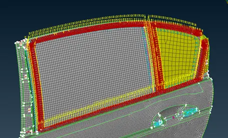
Fig: Oriented Bushing
- For areas with spot weld such as bracket area for connecting rail mechanism and cross beam mechanism. At first we will select COG point and define it as point. We need to understand that spot welding are done on parallel areas only. Under connection manager we will choose appropriate option for spot welding and assign P1 and P2. For Spot ID we will use new Part ID, using PSOLID we will create new solid.
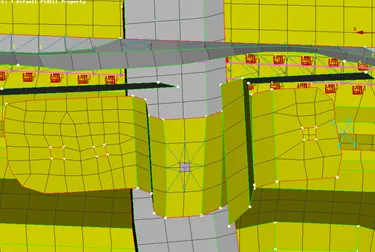
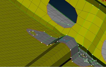
Fig: Spot weld of bracket on rail Fig: Spot weld of cross beam mechanism
- For every other places where there is no geometric definition or no data given we will connect them using the RBE 2 connection. We use parallel entity and connect them.
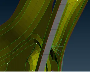
Fig: RBE 2 connection to connect two parts
- For rest of the holes wherever there will be bolting, we will use Cluster RBE 2 connection to constrain them.
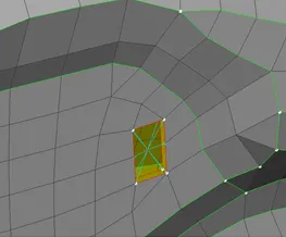
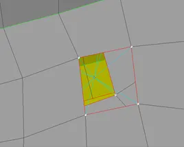
Fig: RBE 2 connection at holes
Result:
We have deployed all the necessary connection to the Rear Door Model.
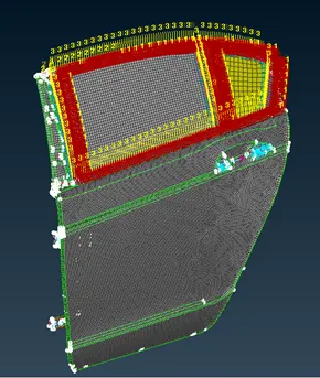
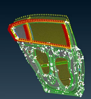
Fig: Connection deployed Rear Door
Learning Outcome:
We understood
- Different type of connectors used for connection.
- Use of suitable tool such as CBUSH, RBE2, SPOT welding.
- Complete implementation of those tool on Rear Door Model on different areas such as door handles, bolts, hinges, latch, window bushes, cross beam as well as railing mechanism.
Rear Door Model Link:
https://drive.google.com/file/d/1v6XC1u7Wm8U-CaAa4YcZo-qBG5Y8o7KA/view?usp=sharing