Thermal Modeling of a Battery Pack
Thermal Modeling of a Battery Pack
Aim:
Simulating the thermal effects and comparing life cycle performance at various temperatures, charge & discharge rates using MATLAB, for a 10 cell series lithium-ion battery model.
Overview:
Battery Thermal Management System:
Electric vehicles (EV) develop fast and have become popular due to their zero-emission and high tank-to-wheels efficiency. However, some factors limit the development of the electric vehicle, especially performance, cost, lifetime, and safety of the battery. Therefore, the management of batteries is necessary in order to reach maximum performance when operating at various conditions.
The battery thermal management system (BTMS) plays a vital role in the control of the battery thermal behavior. The BTMS technologies are air cooling system, liquid cooling system, direct refrigerant cooling system, phase change material (PCM) cooling system, and thermo-electric cooling system as well as heating.
These systems are analyzed through a trade-off between performance, weight, size, cost, reliability, safety, and energy consumption. According to the analysis two prime battery, thermal management systems are recommended: a combined liquid system (CLS) and a variant system with PCM.
The models of CLS and PCM systems were built and simulated using software MATLAB/Simulink.
The simulation results predict the battery temperature variation and the energy consumption of BTMS. Through simulating the PCM system model, the effect of PCM on battery temperature variation was investigated and the proper PCM mass was estimated. As seen from the simulation results, BTMS is of great importance to control battery thermal behavior. Further study could be more comprehensive and accurate by combining the simulation model with battery thermal electric and CFD models.
The methods for Battery Thermal Management are:
Air Cooling and Heating
Air systems use air as the thermal medium. The intake air could be direct either from the atmosphere or from the cabin and could also be conditioned air after a heater or evaporator of an air conditioner. The former is called a passive air system and the latter is an active air system. Active systems can offer additional cooling or heating power. A passive system can offer hundreds of watts of cooling or heating power and active system power is limited to 1 kW. Because in both cases the air is supplied by a blower, they are also called forced air systems. 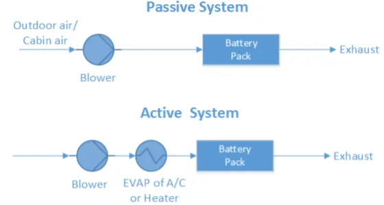
Fig: Forced air systems (passive and active)
Note that the air system offers full functions of heating, cooling, and ventilation. There is no need to build an additional ventilator, but it must be noted that the exhaust air cannot be returned to the cabin again. In some cases, a heat recovery unit (air-air heat exchanger) is mounted after the battery pack in order to recover the heat from the exhaust air. It can prevent a mixture of exhaust air with intake air and at the same time
provide an extra saving potential.
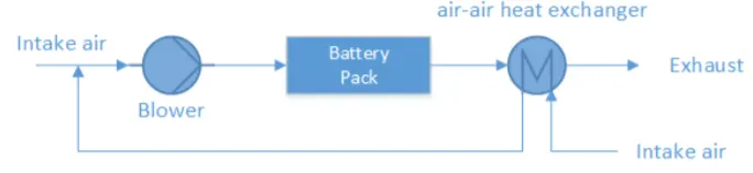
Fig: Forced air system with heat recovery
Liquid Cooling and Heating
Besides air, the liquid is another heat transfer fluid to transfer heat. There are generally two groups of liquids applied for thermal management systems. One is dielectric liquid (direct-contact liquid) which can contact the battery cells directly, such as mineral oil. The other is conducting liquid (indirect-contact liquid) which can only contact the battery cells indirectly, such as a mixture of ethylene glycol and water. Depending on the different liquids, different layouts are designed. For direct-contact liquid, the normal layout is to submerge modules in mineral oil. For indirect-contact liquid, a possible layout can be either a jacket around the battery module, discrete tubing around each module, placing the battery modules on a cooling/heating plate, or combining the battery module with cooling/heating fins and plates. Between these two groups, indirect contact systems are preferred in order to achieve better isolation between the battery module and surroundings and thus better safety performance. By different heat-sinks for cooling, liquid systems can also be categorized into either passive systems or active systems. In a passive liquid system, the heat-sink for cooling is a radiator. This system has no ability to heat. The circulating fluid absorbs heat from the battery pack and releases heat via a radiator. The cooling power depends strongly on the temperature between ambient air and battery. Fans behind the radiator can improve the cooling performance, but if the ambient air is higher than the battery temperature or the difference between them is too small, the passive liquid system becomes ineffective.
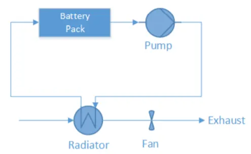
Fig: Passive liquid cooling system
In the active liquid system, there are two loops. The upper is called the primary loop and the lower the secondary loop. The primary loop is similar to the loop in a passive liquid system, where the heat transfer fluid is circulated by the pump. The secondary loop is actually an air conditioning loop (A/C loop). The upper heat exchanger instead of being a radiator works as an evaporator (EVAP) for cooling operation and connects both loops. During heating operation, the 4-way valve will be switched, and the upper heat exchanger works as a condenser (COND) and the lower heat exchanger works as an evaporator. The heating operation loop is also called the heat pump loop.
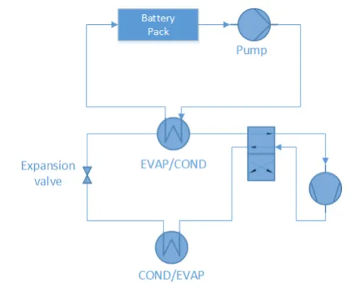
Fig: Active liquid cooling system
Direct Refrigerant Cooling and Heating
Similar to active liquid systems, a direct refrigerant system (DRS) consists of an A/C loop, but DRS uses refrigerant directly as heat transfer fluid circulating through the battery pack.
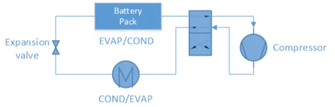
Fig: Direct refrigerant cooling system
PCM
During melting, heat is absorbed by PCM and is stored as latent heat until the latent heat is up to the maximum. The temperature is kept at the melting point for a period and the temperature increase is delayed. Therefore, PCM is used as a conductor and buffer in battery thermal management systems. Also, a PCM is always combined with an air cooling system or liquid cooling system to manage the battery temperature.
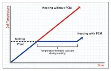
Fig: The working mechanism of PCM on battery cells
Thermo-electric Module
To improve the cooling/heating power of passive air systems, there are two possible upgrades. One is through thermo-electric modules, the other is a heat pipe. The thermoelectric module can convert the electric voltage to temperature difference and vice versa. Here the former effect is adopted. That means it transfers heat through the module by consuming electricity directly. Two fans are installed to improve heat transfer by forced convection. To combine a passive air system with the thermoelectric module, the combined system is able to cool down the battery even lower than the intake air temperature, but the power is still limited to around some hundreds of watts and less than one kW. It’s easy to switch between cooling and heating operations. To achieve that, the poles of electrodes need to be reversed.
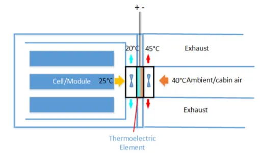
Fig: Thermoelectric cooling/heating system
Heat Pipe
Besides thermo-electric modules, a heat pipe is another way to upgrade passive air systems. The flat copper envelope of the heat pipe was under partial vacuum. The capillary structure is made of sintered copper powder. The heat pipe uses water as the working fluid. Water on the evaporator side will absorb heat and become vapor lower 100°C due to low pressure inside. Water on the condenser will dissipate heat to the surrounding and become liquid again. This cycle repeats again and again. In comparison to thermo-electric, a heat pipe is more reliable, because there are no moving parts and no energy consumption. However, a heat pipe is unable to heat the battery due to its fixed structural layout.
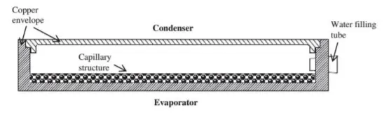
Fig: Structure of the heat pipe
PTC Heater
PTC thermistors have many self-heated applications by utilizing their own voltage-current or current-time characteristics. One of the applications is a self-regulating heater known as a PTC heater. The temperature of a PTC heater can be kept at a fixed point by adjusting the resistance of the PTC heater automatically.
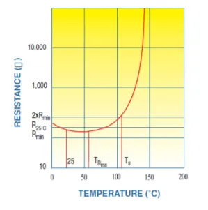
Fig: Resistance versus Temperature for a PTC
Procedure:
I have made the battery using four different packs. Module 1 has 3 cells, module 2 has 2 cells, module 3 has 1 battery, whereas module 4 has 4 cells. These 4 modules will be connected in series in the end.
Going at all the Modules one by one.
Module 1
Module 1 has three cells. These are connected in series. This module is kept in one subsystem. The conduction effect is given parallel to the cells and the convection effect is given towards the cells. For it, we have used the block Conductive Heat Transfer and Convective Heat Transfer, respectively. The temperature sensor is used to measure the temperature of the cell. The battery we use here is table-based, with an instrumented thermal port. The battery is configured with the following datasheet of lithium-ion 18650 cells.
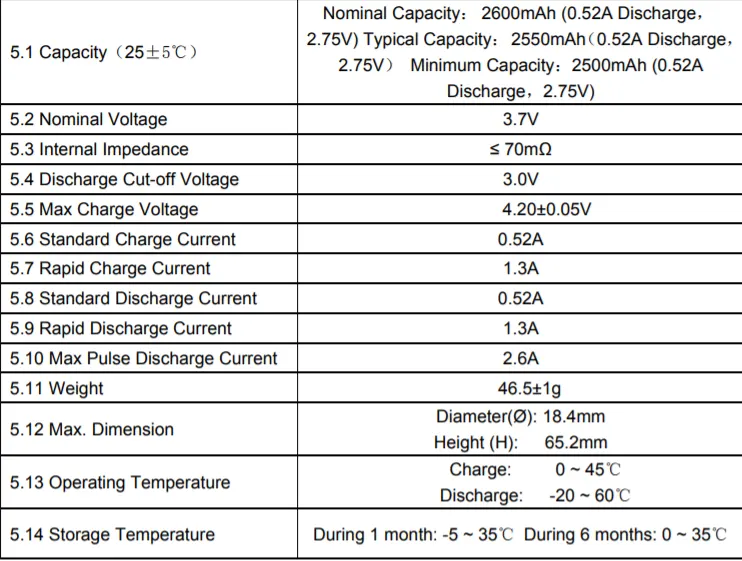
Fig: Lithium Ion cell 18650 Characteristics
The following is a representation of Module 1 in Simulink:
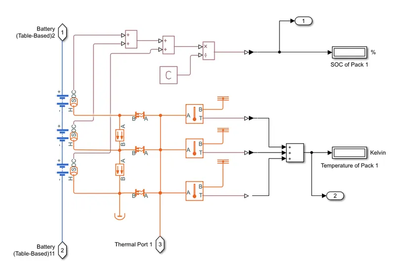
Fig: Module 1
The following is a representation of Module 2 in Simulink:
Module 2
Module 2 has two cells. These are connected in series. This module is kept in one subsystem. The conduction effect is given parallel to the cells and the convection effect is given towards the cells. For it, we have used the block Conductive Heat Transfer and Convective Heat Transfer, respectively. The temperature sensor is used to measure the temperature of the cell.
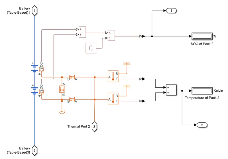
Fig: Module 2
The following is a representation of Module 3 in Simulink:
Module 3
Module 3 has one cell. These are connected in series. This module is kept in one subsystem. The conduction effect is given parallel to the cells and the convection effect is given towards the cells. For it, we have used the block Conductive Heat Transfer and Convective Heat Transfer, respectively. The temperature sensor is used to measure the temperature of the cell.
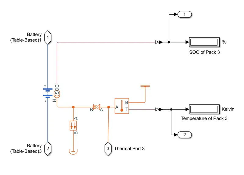
Fig: Module 3
Module 4
Module 4 has four cells. These are connected in series. This module is kept in one subsystem. The conduction effect is given parallel to the cells and the convection effect is given towards the cells. For it, we have used the block Conductive Heat Transfer and Convective Heat Transfer, respectively. The temperature sensor is used to measure the temperature of the cell.
The following is a representation of Module 4 in Simulink:
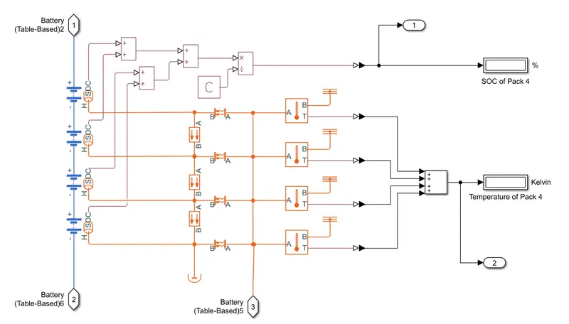
Fig: Module 4
Battery Pack
All four modules are then connected in series. The positive end is connected to the Current Sensor. Which then goes to the Controlled Current Source block. The solver configuration is provided. The end of the conduction was connected to the Perfect Insulator block. The convection port gets the ambient temperature for cooling. This temperature varies, hence we have provided the Controlled Ambient Temperature block. This temperature input is given with the Signal Builder block. All the output of SOC and Temperature are taken as an output for another subsystem using Output block.
The following is the representation of the Battery Pack with Thermal Effect in a varying Ambient Temperature:
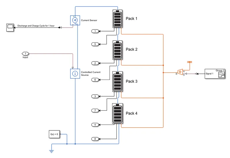
Fig: Battery Pack
The following is the representation of the Varying Ambient Temperature:
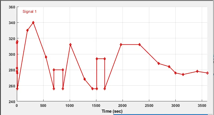
Fig: Controlled Ambient Temperature
Likewise, the battery should get the Drive Cycle to use the Voltage. The Current against Time profile is built using the Signal Builder block. The time scale is 1 hour, which is 3600 seconds.
The following is the Block for providing drive:
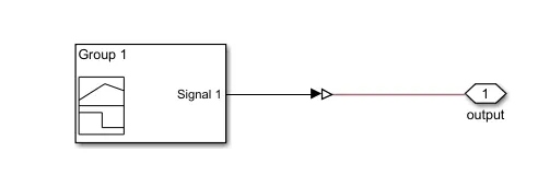
Fig: Vehicle Current Requirement
The following is the input of Current against Time.
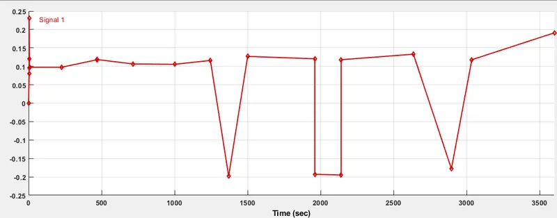
Fig: Vehicle Current Requirement
All the SOC are then added up. Then they are divided by 4 to get the Average SOC. The output of this is connected to the Scope block.
The following is the SOC Calculator:
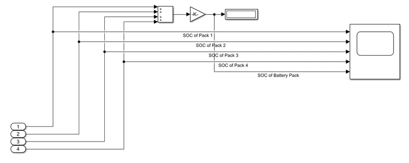
Fig: Battery State-of-Charge
Likewise, the Temperatures are added up, and using gain block, the average is determined.
The following is the Temperature of Battery Pack Calculator:
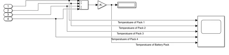
Fig: Battery Pack Calculator
The result of these SOC and Battery, as well as Battery Modules temperature, is shown on the Half Guage and Display blocks respectively.
The following is the real-time result display of the battery and battery modules.
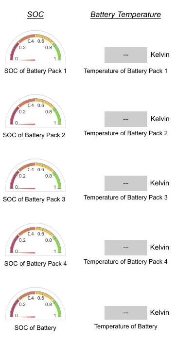
Fig: Display and Half Guage block to display result
For better visuals, the image icons are used to mask the Subsystems.
The following is the Simulink model to simulate the Thermal Effects of a Battery Pack.
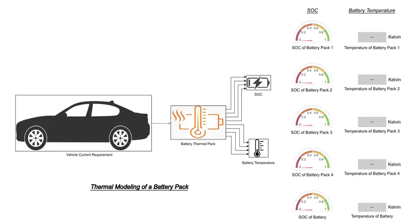
Fig: Simulink model to simulate the thermal effect of a Battery Pack
Result:
The following is the Simulation of a Battery Pack for Thermal Effect
Real-Time Simulation for an Hour
The following is the simulated model of the Battery Pack:
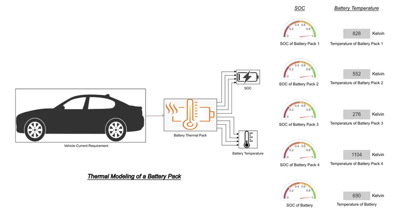
Fig: Simulated Result after 1 hour
It is logical that the module having more cells will have a higher battery temperature. The lowest battery temperature is of module 3 which has one cell at 276 K. Module 2 having two cells has a temperature of 552 K. It is followed by module 1 with 3 cells having a temperature of 828 K. The highest temperature is of module 4 at 1104 K which has four cells. The average temperature is 690 K of the battery after an hour of simulation.
The following is the result of State-of-Charge of Modules as well as Battery Pack:
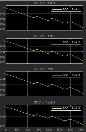
Fig: State-of-Charge of Modules
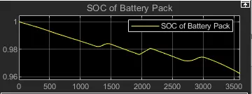
Fig: State-of-Charge of Battery Pack
It is clear from the onset that the State-of-Charge of all the Module has remained the same. The reason being that all the modules are connected in series. This in turn does not affect the total State-of-Charge of the Battery Pack.
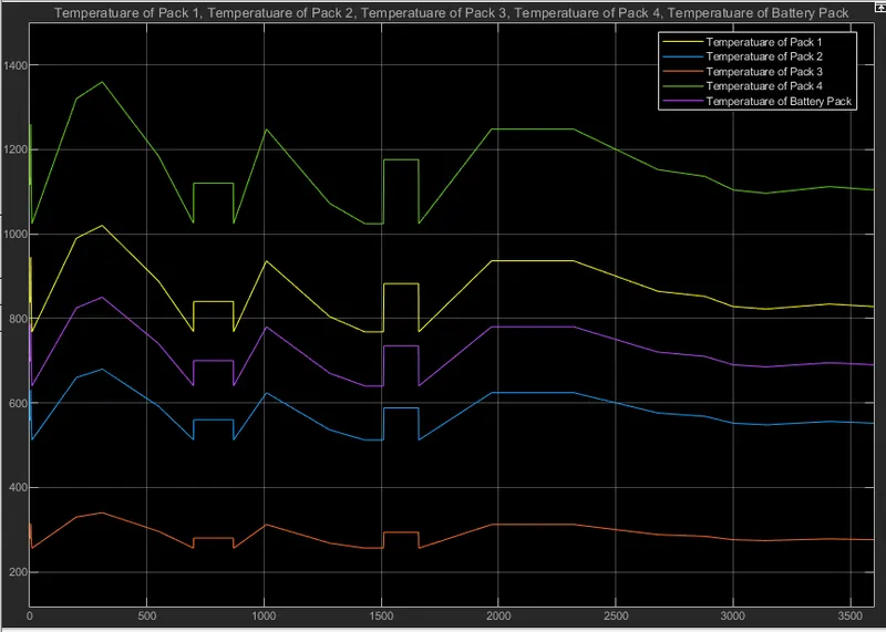
Fig: Temperature of Modules and Battery Pack
The above graph is a testament to the above-simulated result. The lowest battery temperature is of module 3 which has one cell. Module 2 has two cells that have a temperature higher. It is followed by module 1 with 3 cells having a temperature greater than module 2. The highest temperature is of module 4 which has four cells. The Battery Pack temperature is the average temperature of all modules.
The following is the Discharge and Charge Cycle for an hour:
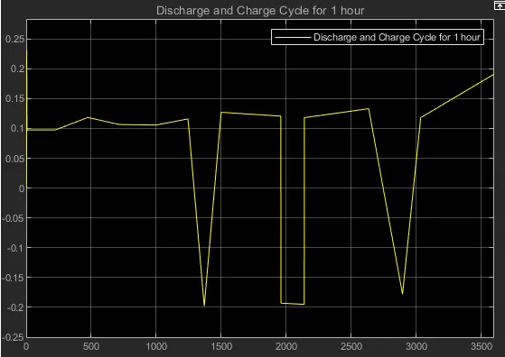
Fig: Discharge and Charge Cycle for 1 hour
It can be seen that, the discharge cycle follows the same pattern as the input vehicle current requirement. The battery is charged at the time when the current goes negative. In the graph such situation occurs thrice, when the battery is charged. Rest of the time the battery is discharged. This is just one cycle when the battery is used for an hour.
References:
http://publications.lib.chalmers.se/records/fulltext/200046/200046.pdf
https://www.ineltro.ch/media/downloads/SAAItem/45/45958/36e3e7f3-2049-4adb-a2a7-79c654d92915.pdf
https://in.mathworks.com/help/physmod/simscape/ug/lithium-ion-battery-pack-with-fault.html
- Habeeb AlasadiExcuse me, can I have the files of the model?