DC Motor Control
DC Motor Control
Aim:
Running MATLAB demo ‘Speed control of a DC motor using BJT H-bridge’ and modifying the model such that armature current doesn’t shoot up when motor changes direction from forward to reverse, comparing ‘The Four-Quadrant Chopper DC Drive (DC7) block’ with BJT H-bridge model and making a suitable EV model using DC7 block.
Procedure:
1. ‘Speed control of a DC motor using BJT H-bridge’
Transistors: Transistors are three terminal active devices made from different semiconductor materials that can act as either an insulator or a conductor by the application of a small signal voltage. The transistor’s ability to change between these two states enables it to have two basic functions:
- Switching
- Amplification
The transistor used in switching applications for Electic Vehicle are;
- BJT: Bipolar Transistors are current regulating devices that control the amount of current flowing through them from the Emitter to the Collector terminals in proportion to the amount of biasing voltage applied to their base terminal, thus acting like a current-controlled switch. A small current flowing into the base terminal controls a much larger collector current. BJT is a current driven device. The power handling capabilities of BJT is lower than IGBT.
The symbol of BJT is as follow:
The Bipolar Junction Transistor basic construction consists of two PN-junctions and a base terminal. These three terminals are known and labelled as the Emitter ( E ), the Base ( B ) and the Collector ( C ) - IGBT: An Insulated Gate Bipolar Transistor (IGBT) is a three-terminal power device which is used as an electronic switch. It is develop to combine high efficiency and fast switching. They are designed to drive high-power applications with a low-power input. They are extremely tolerant to electrostatic discharge and overload. It is used in medium to ultra high power application. IGBT are driven by gate voltage.
The symbol of IGBT is as follow:
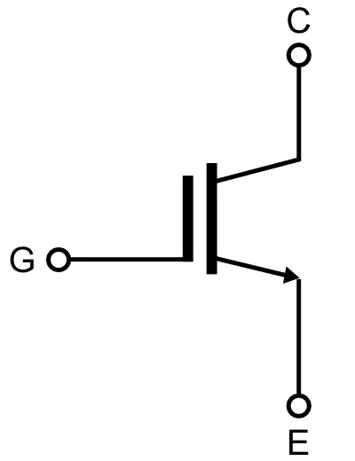
The Insulated Gate Bipolar Transistor is a three terminal semiconductor device and these terminals are named as gate, emitter and collector. Emitter and collector terminals of the IGBT are associated with a conductance path & gate terminal is associated with its controls. - MOSFET: Metal Oxide Semiconductor Field Effect Transistor (MOSFET) is a device which is able to control the voltage and current flow between the source and drain terminals. It works almost like a switch and the functionality of the device is based on the MOS capacitor. The MOS capacitor is the main part of MOSFET. MOSFET is employed in both the analog and digital circuits. This is vulnerable to electrostatic discharge because due to high impedance the voltage dissipation does not take efffect. It is suitable for switching weak signals in electronic devices.
The symbol of MOSFET is as follow:
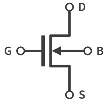
A MOSFET is a four-terminal device having source(S), gate (G), drain (D) and body (B) terminals. In general, The body of the MOSFET is in connection with the source terminal thus forming a three-terminal device such as a field-effect transistor.
The following is the model of a DC motor using BJT H-bridge:
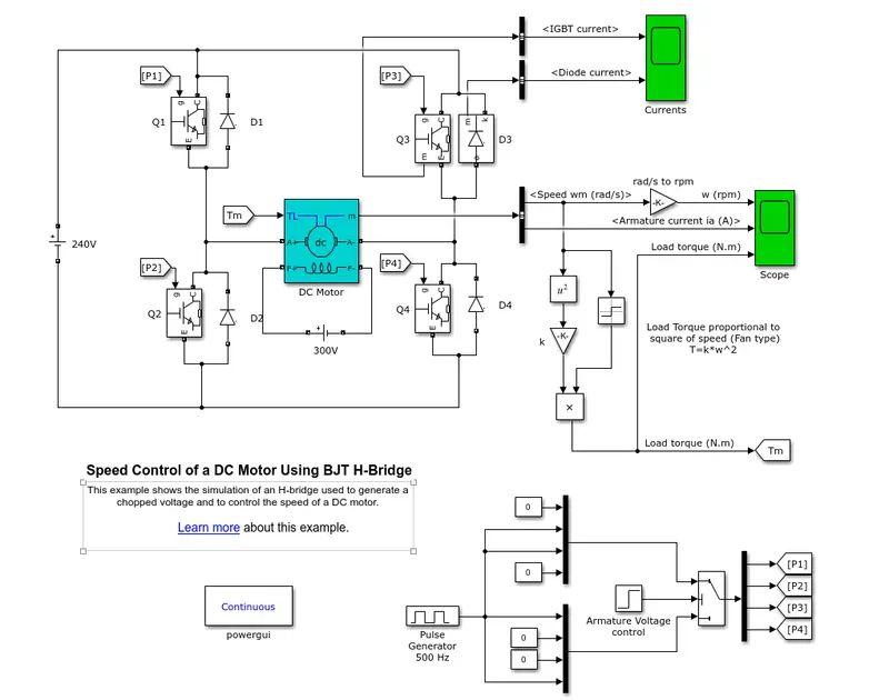
Fig: Speed control of a DC motor using BJT H-bridge
The model above uses H bridge to chopper to step up the voltages and also to control the speed and the way the DC motor works.
The above is a switch that allows the motor to drive bidirectionally. It consist of four switches (IGBT) and four diodes. BJT (Bipolar Junction Transistor) works as an IGBT in switching application. Two transistors are switched simultaneously.
When Q1 and Q4 are switched, the positive voltage flow from positive voltage to Q1, through the motor and Q4. This leads to the forward motion of the motor.
When Q3 and Q2 is switched, the voltage flow to Q3, through the motor and then Q2. This leads to reverse motion of the motor.
When Q1 and Q3 or Q2 and Q4 are switched, then both side of the motor see the same voltage. This is called as braking mode or dynamic braking. By forcing the voltage across the motor to 0, we slow the motor using this short circuit
When either one or none of the switch is closed, then we have coast or free - wheeling. There maybe any voltage across the motor, but we are essentially not provding any current to the motor to cause it to spin.
We use Integrated circuit here, the integrated circuit gives two output. Lets say it is Output 1 to the left of motor and Output 2 to the right of motor. The PWM signal we gives will control whether this output is high, low or turned off.
The logic is;
When both outputs are 0, this gives us the coast mode. Output 1 is high and output 2 is low, it will give forward motion. When Ouput 1 is low and output 2 is high, we get reverse motion. When shorted circuit is used, then it wil be in brake state.
After running the above model the result is as follow:
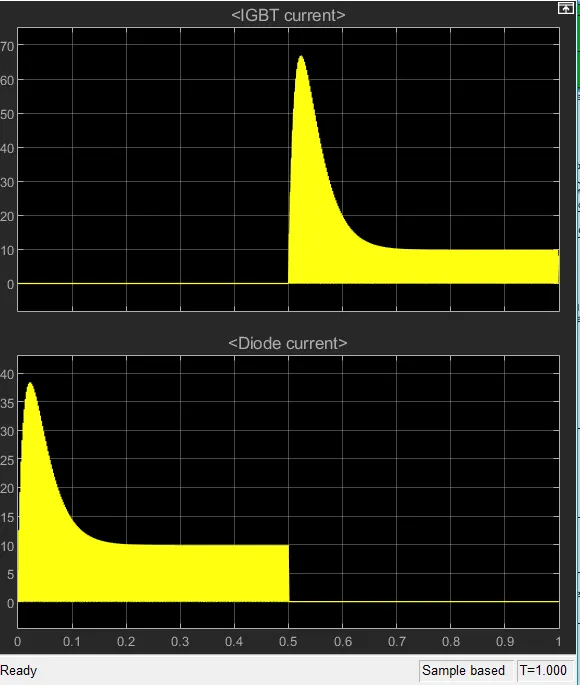
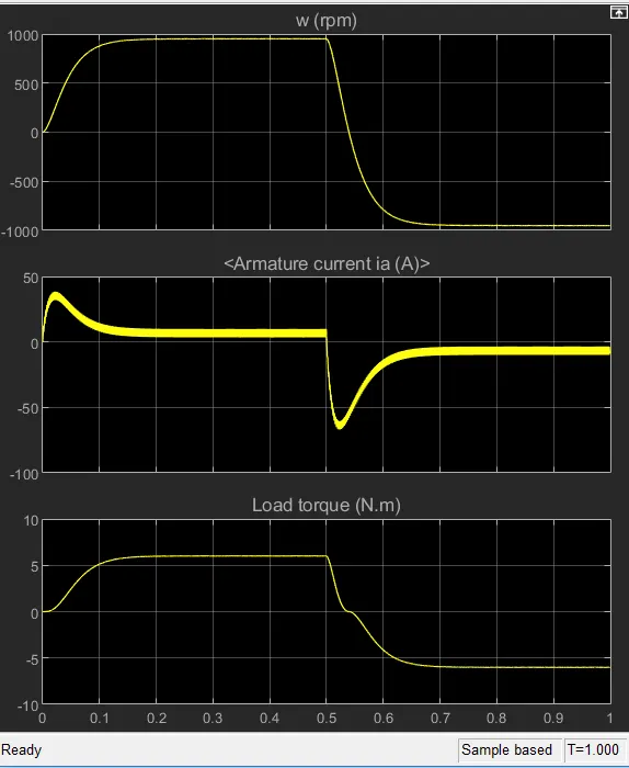
It can be seen that there is increase in the armature current, the reason being that this is due to back emf. The current in reverse and beck emf leads to the high current. This current, if reaches the winding will burn off the winding of the armature. In order to prevent this from happening, we need to avoid the shoot up of the current.
In order to achieve that, we can change the duty cycle and bring the duty cycle down. Lets say the duty cycle is set as 30 % from initial 75 %.
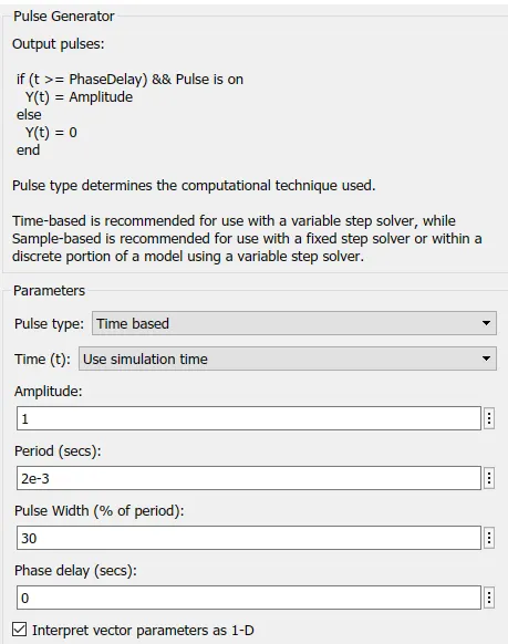
Fig: Change in Duty Cycle
The output can be seen as follow;
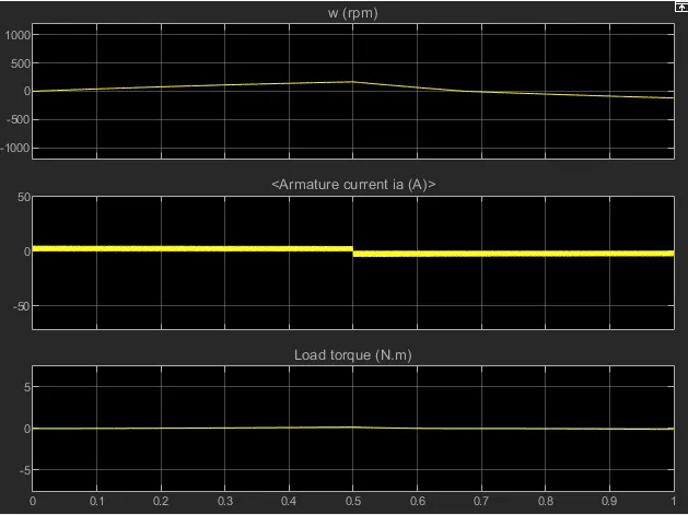
Fig: Output of Armature current
It can be now seen that the armature current does not shoot up as the effect of back emf is nullified by reducing the duty cycle.
2. ‘The Four-Quadrant Chopper DC Drive (DC7) block’
In this, like DC Motor using BJT H-bridge we use four switches and four diode. But the difference is in H bridge, we use the switches simultaneously and in four Quadrant Chopper Switches are not ON simultaneously. They are used as per the operation. In this along with armature is used the armature resistor and inductor.
The below is representation of Four Quadrant Chopper DC Drive,
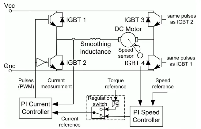
Fig: Four Quadrant Chopper
The Four Quadrant Chopper DC drive works in four mode,
- Forward Motoring mode (First Quadrant)
- Forward Regenerative Braking mode (Second Quadrant)
- Reverse Motoring mode (Third Quadrant)
- Reverse Regenerative Braking mode (Fourth Quadrant)
Forward Motoring mode
In this switch 1 and switch 4 is ON at the beginning. Chopper 1 is in operating condition and chopper 4 is in ON condition. The current flowing though inductor is armature current and the voltage is positive, as the current is flowing from source to load. The output voltage is equal to the terminal voltage. Then when chopper 1 is OFF, the current flow from armature to chopper 4, to diode 2 and again towards the inductor and armature.
Forward Regenarative Braking mode
In this chopper 2 is in ON condition. This leads to flow of current from inductor to diode 4 through chopper 2. The armature current flowing here is going in opposite direction i.e current direction of armature is reversed. In this condition the inductor stores the energy. Now when chopper 2 is OFF, the current flows from D4 to D1 through armature and inductor, and then towards source.
Reverse Motoring mode
In this chopper 3 is in operating condition and chopper 2 is in ON condition. The current flow from source voltage into chopper 3, from there it will go to armature and inductor before finally making its way to chopper 2. The armature current in this case is reversed, and the voltage becomes negative after it passes through armature to chopper 2. Now when chopper 3 is OFF, the current flowing through armature, inductor and chopper 2 will pass through diode 4 before it makes it way to armature again.
Reverse Regenarative Braking mode
In this chopper 4 is in ON condition, the current flow from inductor to armature towards chopper 4, and then the current flows to diode 2 and then again to the inductor and armature. The current flow from positive to negative, hence the current becomes positive but the voltage remains negative. This leads to the storage of energy in inductor. But when chopper 4 is turned off, the current flow from diode 2 to armature and to diode 3 towards source.
The graph of the four working mode is plotted as below;
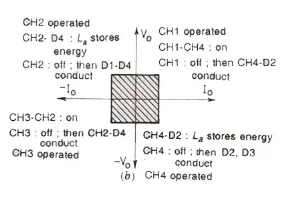
Fig: Working mode of DC motor using Four Quadrant Chopper
It is seen from the above that the Four Quadrant work in four mode and in four quadrant, but BJT H-bridge works in two quadrant i.e it is a Two Quadrant Chopper.
The regeneration is achieved using Four Quadrant Chopper which is not possible in BJT H-bridge.
The above operation can be developed in Simulink using the suitable block. DC7 block is used in this case. The Four-Quadrant Chopper DC Drive using DC7 block is as below;
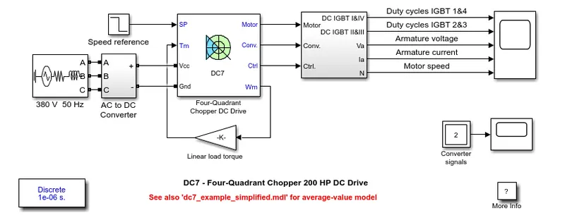
Fig: Four-Quadrant Chopper DC Drive using DC7 block
3. EV model using DC7 block
The torque speed relation is given by the following equation
`T = 24.7 + 0.0051*omega^2`
So in the above, by eliminating the linear load torque, the above equation can be implemented.
The below is the block that represent it;
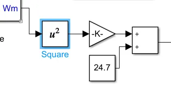
Fig: Simulink Block implementing above Torque-Speed relation
The output speed will be squared using square block, which is multplied with the gain block having values 0.0051. The output of this is added with the constant block having value 24.7. This result is fed to Torque input.
We will create a drive cycle for 10 sec with an input step of 0.1 sec.
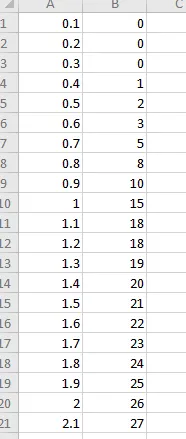
Fig: Drive Cycle for input
The drive cycle is;
https://docs.google.com/spreadsheets/d/19wak98RpcyMCEVCkIct5ThMOGMXu4TRTAgVcpjK1V_Q/edit?usp=sharing
For the operation the battery will be connected. In our case, we have used lithium ion battery. The positive end is connected to voltage input and negative to the ground of Four Quadrant Chopper. The following is the prepared EV model using the torque speed relation;
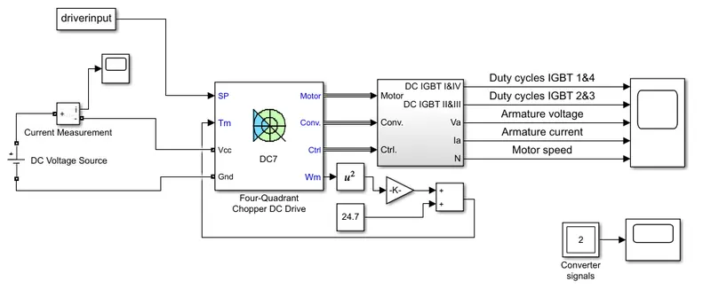
Fig: EV model using DC7 block
The following is the result of the above model that was ran for 10 sec.
The result of the battery during operation is;
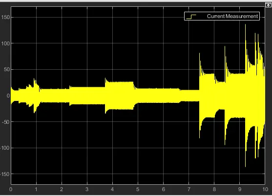
Fig: Battery condition throughout the driving cycle
The following is the output of Four Quadrant Chopper DC Drive using DC7 block;
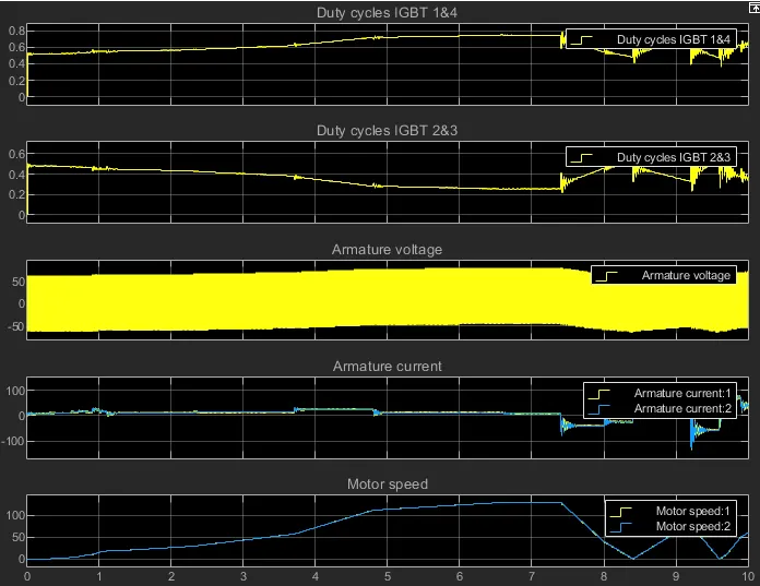
Fig: Output of Motor and switches
Conclusion:
Executed MATLAB demo of ‘Speed control of a DC motor using BJT H-bridge’ and modified the model sin a way that armature current doesn’t shoot up whenever motor changes direction from forward to reverse, made a comparision of ‘The Four-Quadrant Chopper DC Drive (DC7) block’ with BJT H-bridge model, also made a suitable EV model using DC7 block.