EV Drivetrain
EV Drivetrain
Aim:
Explaining types of power converter circuits employed in electric and hybrid electric vehicle, determining EV steady state speed for the condition given as well as illustrating 'Induction vs DC Brushless motor'.
Procedure:
1. Types of Power Converter circuits employed in Electric and Hybrid Electric vehicle
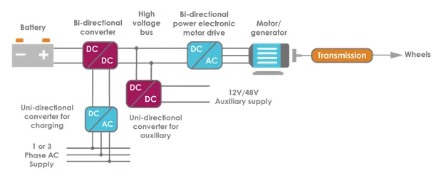
Fig: Power Converter Circuit in EV and HEV
Electrical Drivetrain of EV involves several conversion steps. It contains DC/DC converters, DC/AC as well as AC/DC converter. To regulate the power between the battery and the electric machines, it is necessary to use a power converter device. The battery is a DC supply source, delivering current at a particular voltage. Power flowing into the battery must be processed to ensure it is being delivered at the correct voltage. Similarly, the power delivered by the battery must be processed to ensure the electric machine can provide the optimum power to propel the vehicle.
Converters are made of high power fast-acting semiconductor devices, which act as high speed switches. Different switching states alter the input voltage and current through the use of capacitive and inductive elements. The result is an output voltage and current, which is at a different level to the input.
The different types of Power Converter Circuit are:
a. AC to DC converter (Rectifier)
AC to DC converters are used for charging purpose. Single phase or Three phase AC supply is fed to the Charging port. But this cannot be supplied to the battery. Before it is fed to the battery, it is converted DC using rectifier. This has a unidirectional power flow.
AC to DC converter is also used at the time of regenerative braking, when motor works as a generator. This facilitates bidirectional power flow.
b. DC to AC converter (Inverter)
DC to AC converter is used to convert the DC power of the battery output into the AC power for the motor. This will drive the vehicle. This is bidirectional as it converts AC input to DC output during regenerative braking.
c. DC to DC converter (Chopper)
DC to DC converter are used to convert the DC input from the charging into step down DC output. This happens during charging. But during vehicle propulsion. DC input is converted into step up DC ouput for the motor. When the voltage is increased, it is called step up or boost mode. When voltage is reduced, it is called step down or buck mode. This converter are bidirectional for charging and discharging. Charging is also achieved through regenerative braking.
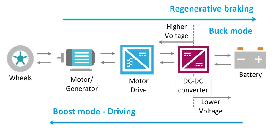
Another place where DC to DC converter are used is in auxillary battery to step up the voltage for the use of accessories. But this is unidirectional power flow circuit.
| Type | ||||
|---|---|---|---|---|
| AC or DC | AC-DC | DC-AC | DC-DC | AC-AC |
| Magnetic Isolation | Isolated | Non-isolated | ||
| Bidirectional power flow | Bidirectional | Unidirectional | ||
2. Determining Steady State Speed for given condition
Voltage = 72 V
Duty Ratio for acceleration operation = d1
Duty Ratio for braking operation = d2
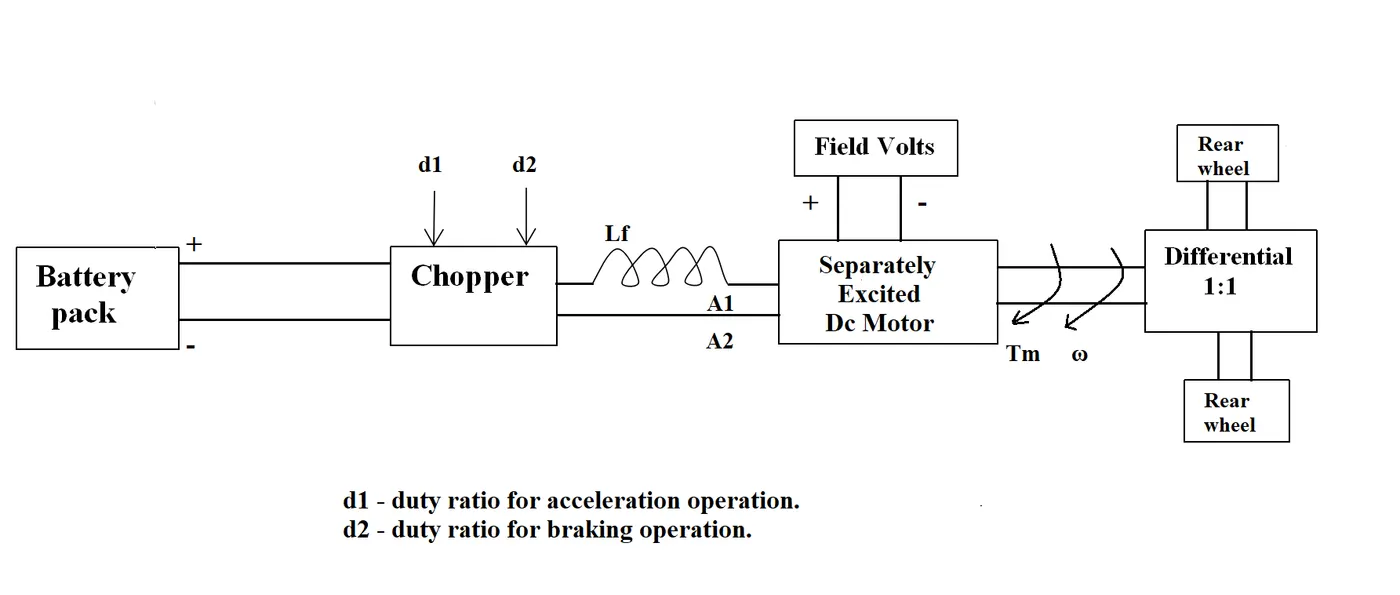
Motor and Controller Parameters:
Rated Armature voltage= 72 V
Rated armature current= 400 A
Ra= 0.5Ω, KΦ= 0.7 Volt second
Chopper Switching frequency= 400 Hz
The given vehicle speed-torque characteristics is;
`Tv = 24.7 + 0.0051omega^2` ---- Equation 1
Duty Cycle = 70 %
As duty cycle is 70 % i.e 0.7
`V = 72*0.7`
`V = 50.4 V`
We know that, the torque - speed relation of DC motor is given as;
`omega = frac{V}{kphi} - frac{Ra}{(kphi)^2}*T`
`therefore omega = frac{50.4}{0.7} - frac{0.5}{0.7^2}*T`
`therefore omega = 72 - 1.0204T`
Rearranging,
`1.0204T = 102.857 - omega`
`therefore T = frac{72}{1.0204} - frac{omega}{1.0204}`
So, `T = 70.5606 - 0.98omega` ---- Equation (2)
Substituting equation (2) in equation (1), we get,
`70.5606 - 0.98omega = 24.7 + 0.0051omega^2`
`therefore 0.0051omega^2 + 0.98omega = 70.5606 - 24.7`
`So, 0.0051omega^2 + 0.98omega - 45.8606 = 0`
We know that, for Quadratic Equation;
`x = frac{-b +- sqrt(b^2 - 4ac)}{2a}`
From above,
`a = 0.0051, b = 0.98, c = - 45.8606`
Substituting values of a,b and c in Quadratic Equation, we get,
`x = frac{-0.98 +- sqrt(0.98^2 - 4*0.0051*-45.8606)}{2*0.0051}`
`therefore x = frac{-0.98 +- 1.3769}{0.0102}`
So, `x = -231.0686 or x = 38.9118`
We will take the positive value.
`omega = 38.9118 frac{rad}{s}`
The Steady State Speed is 38.9118 rad/s
3. Induction v/s DC Brushless Motor
From the article, we understand that,
- The DC Brushless Motor has rotor which includes two or more permanent magnets that generate a DC magnetic field whereas Induction Motor has no magnet and currents flowing in the stator windings produce a rotating magnetic field.
- In DC Brushless motor magnetic field enters the stator core whereas in Induction Motor magnetic field enters the rotor.
- In DC Brushless motor, the stator current need to be continuously varied, and the device that does it is inverter but using 3 phase Induction Motor the torque is produced from the beginning itself and there is no need of inverter.
- Induction Motor is compatible with the power source, whereas the DC Brushless Motor is not, as it requires inverter.
- 3 Phase Induction Motor cannot run from DC input.
- Torque performance of Induction Motor is low as compared to DC Brushless Motor as it has limited starting torque and somewhat limited peak torque.
- The speed of DC Brushless motor is controlled by varying current, whereas the speed of Induction motor is controlled by varying frequency.
- DC Brushless drives require an absolute position sensor, while Induction motor drives require only a speed sensor.
- Less rotor heat is generated with the DC brushless drive as comapred to Induction Motor, as a result, rotor cooling is easier.
- The DC brushless drive can operate at unity power factor, whereas the best power factor for the induction drive is about 85 percent. That is peak point energy efficiency for a DC brushless drive is higher than an induction drive.
- Its not easy to change the magnetic field strength of permanent magnets whereas induction machines have no magnets and magnetic field strength are adjustable.
- Induction machine when operated with a smart inverter has an advantage over a DC brushless machine. This leads to increase in performance.
- In DC brushless, as machine size grows, the magnetic losses increase proportionately and part load efficiency drops. With induction, as machine size grows, losses do not necessarily increase. Thus, induction drives may be the favored approach where high-performance is desired.
- The Peak efficiency of Induction motor is less than DC Brushless motor but the average efficiency is higher.
- Induction motor proves to be cheaper than DC Brushless Motor.
- Achieving stability over the entire torque-speed range and over temperature is more difficult with induction than with DC brushless as induction motor is difficult to control.
- DC Brushless motor is suitable for Hybrid Electric Vehicle and Induction motor is suitable for Pure Electric Vehicle.
Conclusion:
Explained types of power converter circuits employed in electric and hybrid electric vehicle, determined EV steady state speed for the condition given as well as illustrated 'Induction vs DC Brushless motor'.