2D Meshing of an Instrument Panel Substrate
Meshing of an Instrument Panel Substrate
Objective:
Performing Geometry Clean-up to remove any topological error, extracting mid-surface of every sub part and subsequently meshing the Instrument Panel Substrate using the following quality criteria using ANSA.
|
Sr No. |
Quality Criteria |
Value |
|
1 |
Target/Average length |
4 |
|
2 |
Minimum Length |
2 |
|
3 |
Maximum Length |
6 |
|
4 |
Aspect |
3 |
|
5 |
Warpage |
15 |
|
6 |
Skewness |
45 |
|
7 |
Jacobian |
0.7 |
|
8 |
Minimum Quad Angle |
45 |
|
9 |
Maximum Quad Angle |
135 |
|
10 |
Minimum Tria Angle |
30 |
|
11 |
Maximum Tria Angle |
120 |
|
12 |
Tria Percentage |
15 |
|
13 |
Tria per node |
2 |
Instrument Panel Substrate:
Instrument Panel substrate is a part of the dashboard or instrument panel that has a provision for keeping the parts of the panel intact. Instrument panel is a control panel usually located directly ahead of a vehicle's driver, displaying instrumentation and controls for the vehicle's operation. Its prime importance can be understood by the part it holds. As a result, IP substrate become an all-important member, because it does the work of keeping the parts of the instrument panel in place.
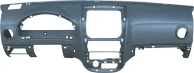
Fig: Instrument Panel Substrate
The substrate may be formed from a rigid material, such as metal or rigid plastic. The instrument panel doesn’t necessarily need to have heavy weight material to keep part intact, rather it can be done using the part that is lighter, save costs. But we need to make sure that the material is rigid and design good enough so that material does not fail in NVH test.
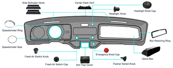
The above figure depicts the parts that the IP substrate holds. In the absence of this parts the driver does not get a complete manoeuvring detail. There are many other controls that are put onto the substrate for easy control. Other essential that are put onto are the knobs.
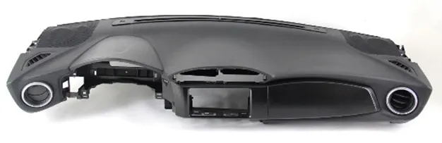
Fig: Subaru Scion FR-S IP substrate
The above is the Instrument Panel Substrate of Subaru Scion FR-S model. The control panel are intact in the substrate. Thanks to modern plastics technology, instrument panels are often made of acrylonitrile-butadiene-styrene (ABS), ABS/polycarbonate alloys, polycarbonates, polypropylene, modified polyphenylene ether (PPE) and SMA (styrene-maleic anhydride) resins. These plastics allow for complex designs in items such as airbag housings, centre stacks for instrument panels, and large, integrated instrument panel pieces.
Wholly integrated single-piece units can be manufactured from all-urethane and all-polypropylene resins. This results in a seamless instrument panel with greatly reduced NVH levels, moulded-in colour and with significant cost savings for the manufacturer. Cost effective post-consumer and in-plant recycling are also achievable.
This 2017 Lincoln Continental instrument panel is claimed to be the thinnest full-size, deep-draw injection moulded IP in North America at 1.9 mm/0.07 in. This design was 14% lighter and saved money in materials investment.
Procedure:
Step 1: Geometry Clean-up
- The very first step involve opening the CAD geometry in ANSA readable format. The CAD file is the half portion of the IP Substrate, and it can be seen that the faces of the CAD are not stitched with each other, as evident from Single Con. Before we proceed any further, we need to stitch these faces uses TOPO command. After its use we can see that geometry are stitched with each other by Double Cons.
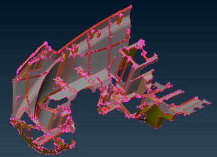
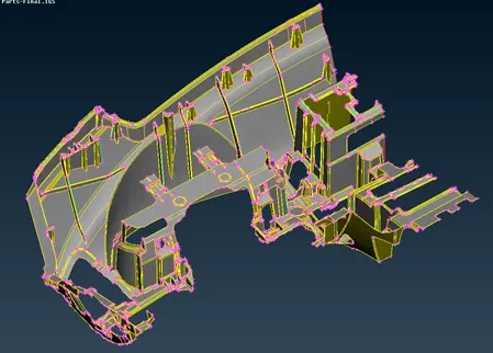
Fig: Before TOPO Fig: After TOPO
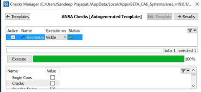
- Next step involves checking for any geometrical issues. Before we proceed ahead, we need to make sure that the part is free from any topological error. This is done in order to make sure that the CAD has good quality for meshing. We will do the Geometry Check, and it is evident that there is a list of geometrical error. We will clear every geometrical issue.
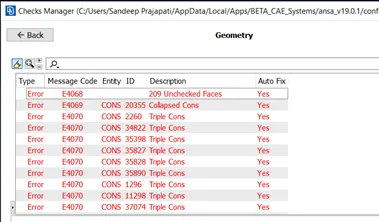
Fig: Geometry Check
- Apart from Triple Cons and Unchecked faces, we can see that there are Broken Faces. This arose from the fact that this is the half portion of the IP substrate and in the process of removing half part, the cross-sectional portion remained open. We will stitch them by filling that portion with the new Faces using Coon option.
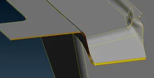
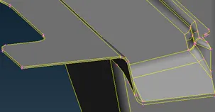
Fig: Before Patching Fig: Patching open faces
- We will do this geometry clean-up to the point that there is no geometrical error. And on execution we get the green signal.
Step 2: Mid-surface Extraction
In the substrate there is the main body of the substrate, and in the main body there are many intricate parts such as ribs, dog pins, side support, supports and various features. The features are different, the thickness of the ribs are different, thickness of support is non uniform and dog pins vary from each other. So, while extracting the mid-surface we will extract the mid-surface of each part individually and set them into their respective PID.
- First, we will begin with mid-surface extraction of the whole body. The main body covers up the maximum portion of the substrate. Every feature, support and ribs are present on main body. As a result we would first extract the mid-surface of the main body and then the other sub-parts. The thickness of main body is 0.6 mm. So, we will extract the mid-surface for the entire body at 0.3 mm using the Offset command. We will select each macro region of the body before we proceed for mid-surface extraction.
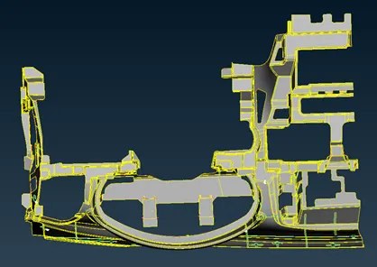
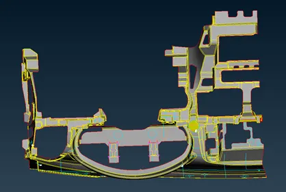
Fig: Substrate Fig: Mid-surface of Main Body
- Once we are done with the main body, we will extract mid for the other part. Here I went, for the support area first. The support in itself is made of sub parts having different thickness. So, we will extract mid of each part. We will use the New faces to fill up the spaces that come due to mid-surfacing and use Extend command to connect the side support to its sub parts and to the main body. There are two side support having thickness of 4 mm and 3 mm with its ribs having thickness of 2.22, 1.69, 1.64 and 2.5, 2, 1.94 respectively. So we will extract mid surface at 2 mm and 1.5 mm and its ribs are 1.11, 0.85, 0.82 and 1.25, 1, 0.97 respectively.
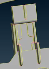
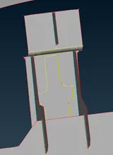
Fig: External support Fig: Mid-surface of external support
- Dog pins are solid component, but we will define it as a 2D component. We will use offset of 0.5 mm for the dog pins and set the PID. While setting PID we will give it a thickness of 1 mm. using the New faces command we will patch up the faces and by Extend command we will join the surfaces. There are total 17 dog pins. We will do this process for the remaining dog pins.
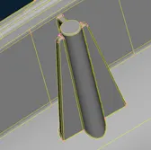
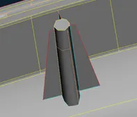
Fig: Dog Pins Fig: Mid-surface of dog pins
- Ribs are an important feature that provides strength to the structure. In the substrate there are various places, where there are ribs. The ribs depending on the location has different design as well as varying thickness. The ribs connected to dog pins are used for support purpose. Here too, the ribs have varying thickness depending on the location. Some of them are in the following.
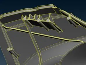
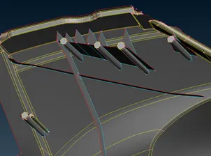
Fig: Ribs Fig: Mid-surface of ribs
The above intersecting ribs have thickness of 2 mm and 2.5 mm. So, we will have the mid-surface at 1 mm and 1.25 mm.
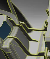
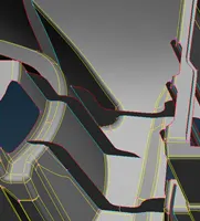
Fig:Ribs Fig: Midsurface of ribs
The above ribs have thickness of 2 mm, 2.63 mm and 1.61 mm. Although they are based in the same location, they have a varying thickness. We will extract their mid-surface individually and set them in different PID
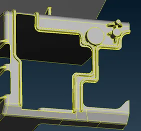
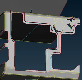
Fig: Actual part Fig:Midsurface
The above portion has many intricate portion such as ribs and dog pins in the same location. Here too, we will extract mid-surface by offset and set it in different PID and then remove mid surface for dog pins as mentioned above.
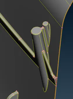
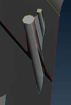
Fig: Actual part Fig: Mid-surface
The same process is done for extracting the mid-surface of the above parts. We need to make sure that all different part is set in their respective PID.
- For the feature below, we see that the from one side we have the feature but from the other side the portion is flat. Here we will ensure to keep both of that. As a result, due to intersection we can see Triple Cons. Instead of extracting the mid-surface of both side, we will extract mid-surface of the feature area, then patch the open flat portion.
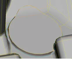
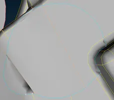
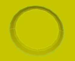

Fig: Feature view from top and bottom
We need to make sure that the PID of all part is set, before we begin meshing.
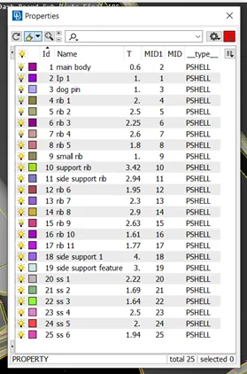
Fig: Properties ID
Step 3: Meshing
1. Before meshing we will set the Mesh Parameter and Quality Criteria. In mesh parameter, we will set the target element length as 4 mm and Mixed meshing. In quality criteria we will set the minimum length as 2 mm and maximum length as 6 mm. Likewise we will set the rest of the parameter in quality criteria.
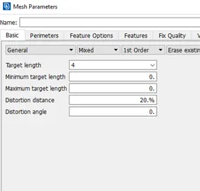
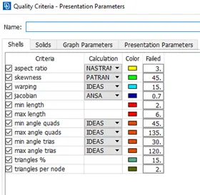
Fig: Mesh Parameter Fig: Quality Criteria
2. In order to improve the meshing, we will rearrange some construction line or remove some unnecessary lines. If we keep this, the meshing will not yield a good result. It will result in number of quality error in single place.
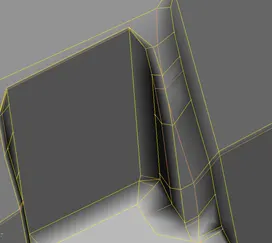
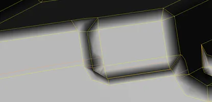
3. We will use the Best command to mesh the entire region in a single time. But we can see that the region has plethora of quality issues, we need to sort these quality issues before we can say that the part is properly meshed. We will use Reconstruct command to make the mesh better as well as reduce the quality issues.
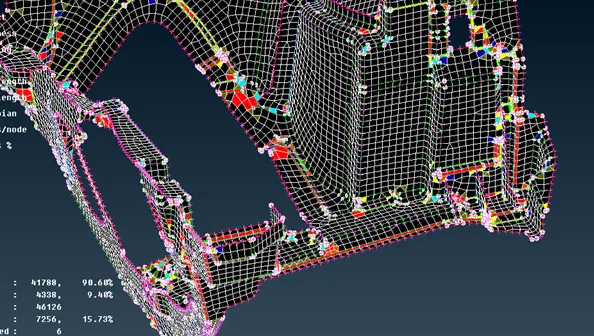
Fig: Before
Most of the quality issues will be seen at the areas of ribs and features. We will Reconstruct the Macro region or rearrange the construction line in such areas. The other areas where there will be quality issues will be the area where triple cons intersect, or triple cons are present near the double cons.
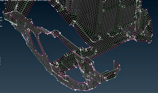
Fig: After
There will be areas, that will be problematic. For such areas we will split them into different parts using CUT option. Other areas where there is poor meshing result or the quality is poor are the areas where double cons are close to the intersection of the ribs on dog pins, or external support region. We again will use the series of option such as Reconstructing macros region or rearrangement of construction line in the area.
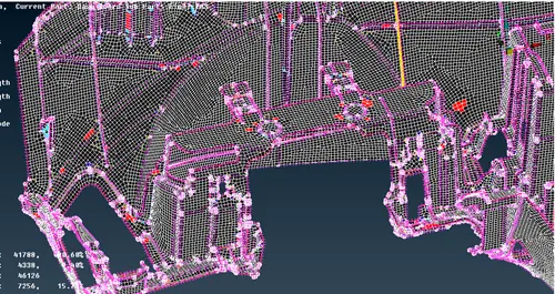
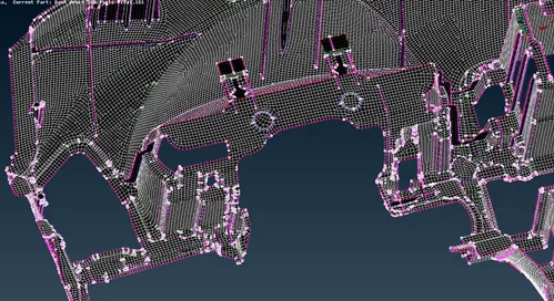
Fig: Before Fig: After
There are many areas where the quality errors cannot be removed due to the minimum length or geometric constraints, those are the region we will leave and proceed with the mesh correction step. The step involves removing the opposite trias or removing the trias element from the perimeter as much as possible. Another trias element that needs addressing is back to back trias, but we will remove the one which are possible to remove because the errors such as jacobian or skewness in many areas are removed by splitting the element in two. In such areas the back to back trias will remain. We will try to refine the mesh to get the better mesh result.
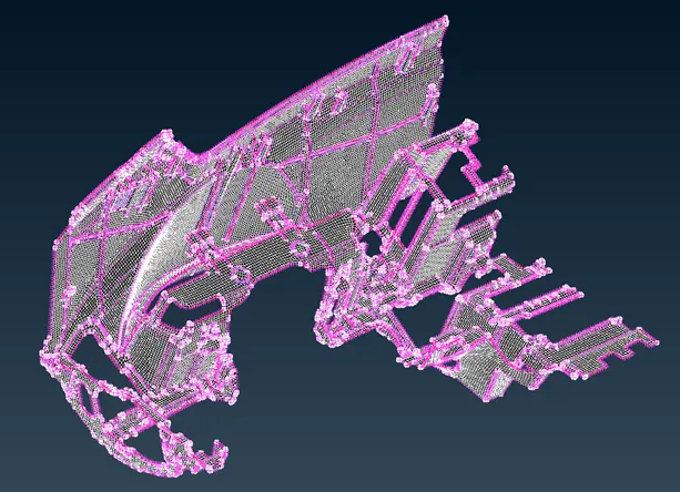
Fig: Meshed Instrument Panel Substrate
Result:
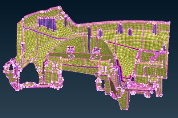
Quads = 44076 (94.01 %)
Trias = 2811 (5.99 %)
Total = 46888
Learning Outcome:
- Geometry clean-up
- Extracting mid-surface
- Assigning PID of individual parts
- Rearranging construction line
- Meshing
- Mesh Refining
Conclusion:
The meshing of Instrument Panel Substrate after clean-up of topological error is done.