Meshing of Vehicle Suspension Assembly
The Meshing of Vehicle Suspension Assembly
Aim: Performing Geometry Clean-up, 2D Meshing & 3D Tetrahedral Meshing of Vehicle Suspension using the following quality criteria and providing the appropriate connections using ANSA.
Quality criteria for Mixed elements (For Midsurface only)
|
Sr No. |
Quality Criteria |
Value |
|
1 |
Target/Average length |
4 |
|
2 |
Minimum Length |
2 |
|
3 |
Maximum Length |
6 |
|
4 |
Aspect |
3 |
|
5 |
Warpage |
15 |
|
6 |
Skewness |
45 |
|
7 |
Jacobian |
0.7 |
|
8 |
Minimum Quad Angle |
45 |
|
9 |
Maximum Quad Angle |
135 |
|
10 |
Minimum Tria Angle |
30 |
|
11 |
Maximum Tria Angle |
120 |
|
12 |
Tria Percentage |
15 |
|
13 |
Tria per node |
2 |
Quality Criteria for Tria Elements (Tyre and Rim):
|
Sr No. |
Quality Criteria |
Value |
|
1. |
Target/Average length |
6.5 |
|
2. |
Minimum length |
5 |
|
3. |
Maximum length |
10 |
|
4. |
Skewness |
45 |
|
5. |
Tet-collapse |
0.2 |
Quality criteria for Tria (For other components):
|
Sr No. |
Quality Criteria |
Value |
|
1. |
Target/Average length |
4 |
|
2. |
Minimum length |
2 |
|
3. |
Maximum length |
6 |
|
4. |
Skewness |
45 |
|
5. |
Tet-collapse |
0.2 |
Objective:
- 2D Meshing of Wishbone, Suspension lower strut, and its side support
- 3D Tetrahedral Meshing of the rest of the part
- Providing appropriate connection
Theory:
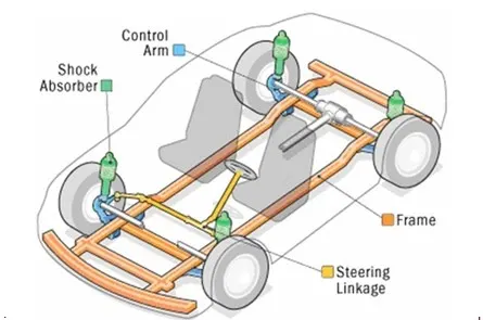
Fig: Suspension
The function of car suspension
When most people think of automotive performance, they think of power, the need for speed, the roaring sound of the engine, and how fast the vehicle will go from zero to 60 miles per hour. However, all this power and speed is useless if the driver is unable to control the vehicle and is not comfortable while driving. Therefore, automotive suspension is a crucial vehicle system.
The primary functions of the suspension system include:
- Maximizing the contact between the tires and the road surface.
- Providing steering stability and good handling.
- Evenly supporting the weight of the vehicle (including the frame, engine, and body).
- Ensuring the comfort of passengers by absorbing and dampening shock.
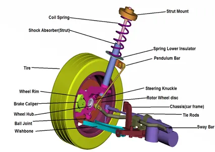
Fig: Part of Suspension Assembly
The suspension system consists of tires, the air in the tires, springs, shock absorbers, struts, arms, bars, linkages, bushings, and joints. The suspension system components are located between the frame of the vehicle and the road. Well-tuned suspensions will absorb bumps and other imperfections in the road allowing the people inside the vehicle to travel safely and comfortably.
The suspension system requires the wheels and tires to travel up and down to absorb the shock from bumps. The rubber tires and air in the tires also soften the ride over hard surfaces and conform to slightly uneven and rough surfaces.
Shock absorbers, also known as shocks, are hydraulic oil-filled cylinders that force the suspension to compress and decompress at a consistent rate to prevent the springs and vehicle from bouncing up and down. Many vehicles use struts, which are similar to shocks, that sit in the center of a coil spring. Strut assemblies consist of a coil spring to support the vehicle's weight, a strut housing to provide rigid structural support for the assembly, and a strut cartridge. Struts perform a damping function like shocks. Internally, a strut cartridge is similar to a shock. A strut assembly provides structural support for the vehicle suspension, supports the spring, holds the wheel and tire in the aligned position, and ensures the tire maintains contact with the road. Struts also bear much of the side load placed on a vehicle's suspension. As a result, strut assemblies affect riding comfort and handling as well as vehicle control, braking, steering, wheel alignment, and wear on other suspension components and the tires.
Types of Suspension
- Swing axle.
- Sliding pillar.
- MacPherson strut/Chapman strut.
- Upper and lower A-arm (double wishbone)
- Multi-link suspension.
- Semi-trailing arm suspension.
- Swinging arm.
Working of A Suspension
A suspension works on the principle of force dissipation which involves converting force into heat thus removing the impact that force would have made. It uses springs, dampers, and struts to achieve this. A spring will hold the energy while a damper will convert it into heat.
Procedure:
1. Geometry Clean-up
First, we will open the CAD geometry of the Vehicle Suspension in the ANSA readable format.
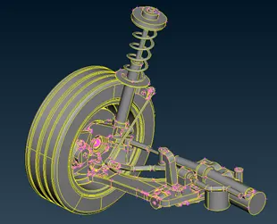
Fig: Suspension Assembly CAD
After opening the CAD geometry, we will find out that we have a half a portion of the vehicle suspension. The vehicle suspension is usually symmetric, as a result, we will work on the portion of the vehicle suspension only.
We will go to the Geometry Check and Check for any topological error. Most of the problem that the model has, is because of the triple cons due to intersecting faces or common cons. Another error is due to the open faces of the wheel hub.
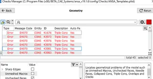
Fig: Geometry Check
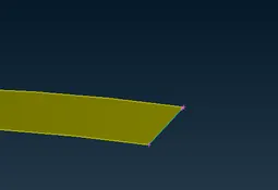
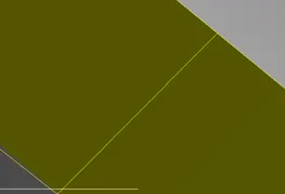
Fig: Resolved Triple Con
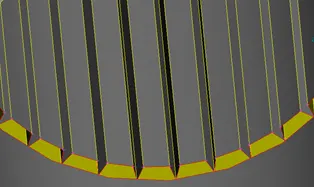
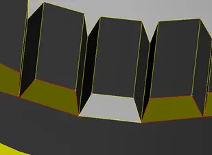
Fig: Patched faces
To remove triple cons, we will go to that particular portion and remove the triple con. we will first release the cons and then individually do the topo of that particular part individually
To fix the single cons issue, we will find out that due to the not patching of the area we have the problem of single cons. To remove that, we will create a new face using the con option. But before that, we will project the single cons.
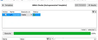
Fig: Error-free check
We will do these until we get no errors and the geometry check prompt tab gives a green signal on execution.
- Meshing
- 3 D Tetrahedral Meshing
For Volumetric meshing we Spot Mesh. Meshing can be done in two ways. By Ortho Tria element and by normal tria element. Ortho Tria is used on a curved surface to preserve the curve feature and normal tria is used on a flat portion to save the computation time, and ortho tria is not needed there, as there is no feature or curve to capture properly. There are many algorithms to mesh the volume. We use Tetra Rapid and Tetra FEM based on the better result they provide.
- The meshing of Wheel and Rim
For the meshing Wheel and Rim, first, we will need to set the mesh parameter and quality criteria. we will set the quality criteria as follows. Minimum length = 5, maximum length= 10 skewness = 45, tet collapse = 0.2
Wheel
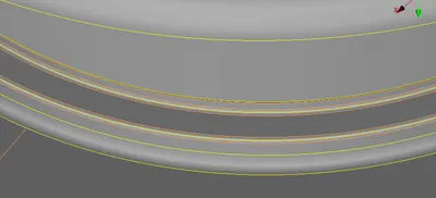
Fig: Rearranged construction line
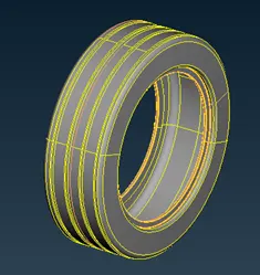
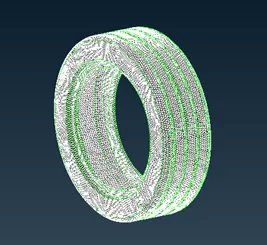
Fig: Meshing of Tyre
We will first select the curve portion of the wheel. At some places near fillet, the construction line is too close. What it does is that, in that particular location, the part will fail for quality. As a result, using curve middle command we will first make a curve, and using the project under con, we will project that on the face and then delete the actual two lines. This line captures the feature and eliminates the error in that region. By using the Ortho Tria we will mesh that portion. Before we go for the rest of the portion, we will correct most of the issue here and then we will mesh the rest of the portion of the wheel using normal tria. Using construction on relative faces, we can solve most of the error, every error will be eliminated, the error that will remain are the one on the thread portion having a minimum length. We cannot remove that error at the expense of feature distortion. Once this is done, we will define the volume.
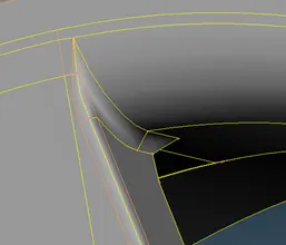
Fig: Rearranged construction lines
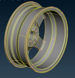
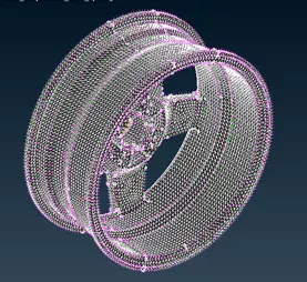
Fig: Meshing of Rim
Rim: Most of the areas that will have a problem with meshing are near the bend holding the spook of the rim. We will remove the unnecessary construction lines. We will generate a middle curve and subsequent lines to eliminate the line that is close to each other. Here again, we will repeat the step of ortho tria on the curve portion and normal tria on the flat portion. The only area that will have a problem will be the step portion of the inner of the rim. Again here we cannot do major reconstruction to distort the feature. We will use a series of operation such as move, split and reconstruct to solve most of the issue
Once the surface mesh is done we will define the different volumes of both wheel and rim and give it different PID under PSOLID. Once this is done, we will use Tetra Rapid and Tetra FEM meshing on both. We see that Tetra Rapid gave no tet-collapse issue, hence we went ahead with Tetra Rapid mesh of both Wheel and Rim
- The meshing of the rest of the part
First, we will reset the mesh parameter and quality criteria to mesh the rest of the part of the suspension.
Then, we will approach for surface meshing of each and every part one at a time. At the wheel disc, the portion of the fillet is the area of concern and the small support between disc. All the error does go away on reconstruction. The support area needs to be taken separately for reconstruction as it will disrupt the rest of the corrected mesh. We will take it separately to mesh and reconstruct
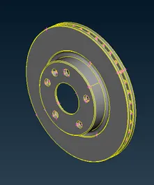
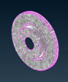
Fig: Meshing of the wheel disc
For the wheel hub, the only portion that causes quality issues on meshing is inside holding teeth. We will delete the actual faces to make it a flat face as a whole. First, we will delete the submerged faces, and then using the new faces option we will create a new face or simply patch the region. The unnecessary hot points present in the region should be deleted. Doing this will resolve quality errors such as minimum length, maximum length, and skewness in that particular region. This in turn will give a better mesh for computation.
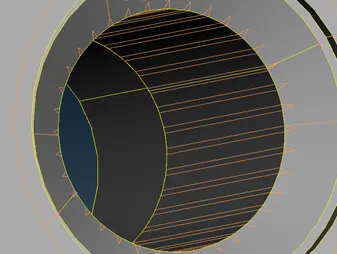
Fig: Patched wheel hub area
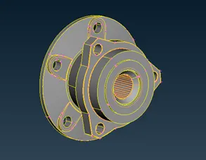
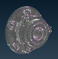
Fig: Wheel Hub Meshing
Once this is done, we will first define both areas and then we do Tetra Rapid Meshing as this gives results without tet-collapse.
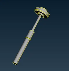
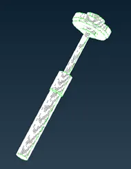
Fig: Suspension Meshing
At suspension barring the side plate and lower strut mount, we will do surface meshing of the rest of the part. In this part, there is no area of concern. There is a total of 5 parts of suspension out of which four will be surface meshed for volumetric meshing. Once the surface mesh is done, we will define each volume individually and then use Tetra Rapid to do volumetric meshing.
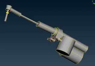
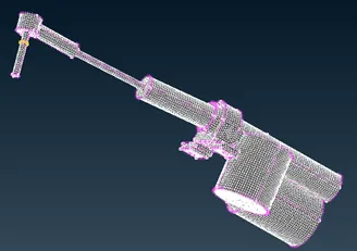
Fig: Sway Bar Meshing
Tie Rods and Sway bars are portions, where we find skewness error at some places. This happens because of the construction constrain in the area. So such are the areas that we will compromise for quality as we do not want to disrupt any feature.
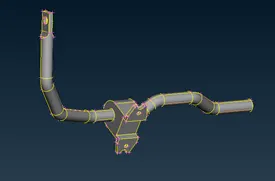
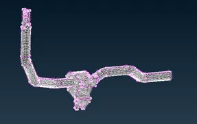
Fig: Tie Bar Meshing
At linkers, the link connecting suspension to the chassis frame is the pendulum bar. At the pendulum bar one of the parts fails for quality due to minimum thickness. So for this area, we will remove the extended portion and patch up the overhang portion.
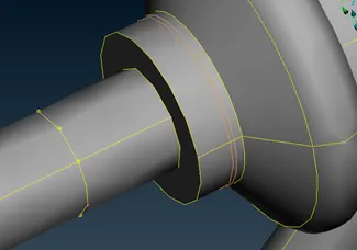
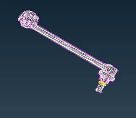
Fig: Pendulum Bar Meshing
Brake calipers are one area where construction lines are close to each other and they have prime importance. Some parts cannot be rearranged. For this too, there would be skewness error at some places. But the volumetric meshing will not have a problem of tet-collapse.
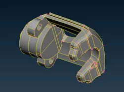
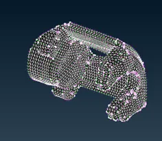
Fig: Brake Caliper Meshing
The chassis is the structure supporting the car. By using the Spot mesh, the chassis can have meshed on the surface. Chassis again have areas with few skewness errors, it can be compromised to have a better capturing of the feature.
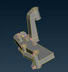
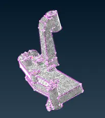
Fig: Chassis Meshing
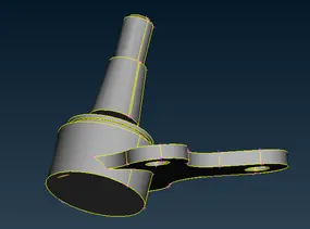
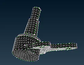
Fig: Ball Joint Meshing
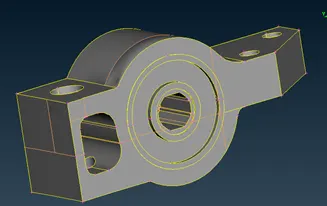
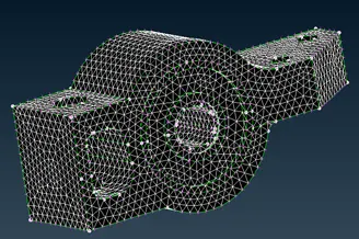
Fig: Bush Meshing
- 2D Meshing.
There are a total of three parts where we deploy 2 D meshing
They are suspension side support, wishbone, and suspension lower mount strut.
The suspension side support has a thickness of 3 mm. Using the offset command, we will offset it at a 1.5 mm distance and extract its mid surface.
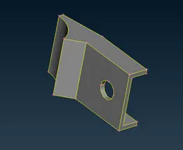
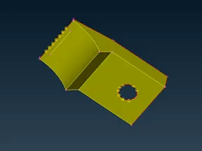
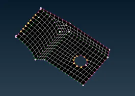
Fig: Side Plate Meshing
Once that is done, we will extract mid surface for the suspension lower portion, which is the lower mount strut.
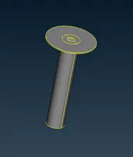
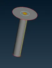
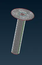
Fig: Lower Strut Meshing
The wishbone has a portion of varying thickness, we will extract it accordingly and set the PID for each and every part.
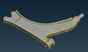
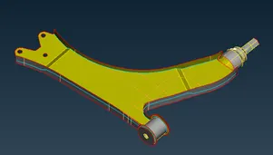
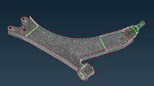
Fig: Wishbone Meshing
Once it is done, we will set the meshing parameter and quality criteria for meshing. The minimum length and maximum length is set as 2 mm and 6 mm respectively, and the average length is set as 4 mm.
We will use BEST mesh for the first mesh and then reconstruct the mesh. At places with the back to back trias, opposite trias, and trias at edges, we will work it out to fix it.
- Connections
The parts of the suspension assembly are connected with each other by bolts and welds. There is also spring in the suspension assembly. At pendulum bar connection we need to denote the connection
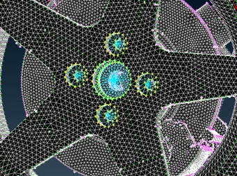
Fig: RBE 2 connection at the rim
For Wheel Rim, we will use the RBE2 connection Many Nodes. We will select the areas that will be used as a purpose of bolting, and then the master node shows up. We will click on Okay and continue.
Other areas where bolting takes place is the connection of the wheel hub to the suspension. The connection at both ends of the wheel hub will be assigned with Many nodes RBE 2 connection. And then, we will use Two node RBE 2 connections, to connect the two master nodes.
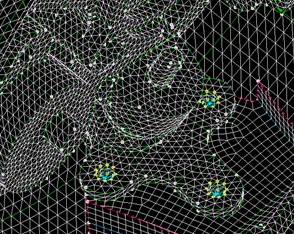
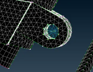
Fig: RBE 2 connection at Kingpin and Wheel Hub connecting with suspension
The ball joint is connected to the wishbone using spider RBE 2 connection because there will be bolting in this region.
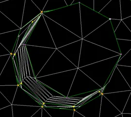
Fig: Two nodes RBE 2 connection at pendulum bar
Other areas where connection needed are between wishbone and chassis, and between tie rod, sway bar, and chassis. This is also done using RBE 2 connection
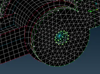
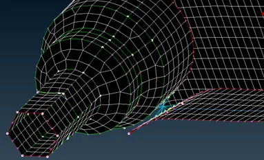
Fig: RBE 2 connection at Wishbone
The circular portion at the end of the wishbone that goes into bushing is also not joined to 2 D of the wishbone. Here we will display connection, by deploying an RBE2 connection between the element.
In order to get make the connection with the pendulum bar, we will first project the construction line of the tie rod and side plate on either side of the pendulum bar. This needs to be done before meshing. Once this is done, we will connect at least 5 nodes of both parts using 2 nodes RBE 2 connection.
For spring, we first create a curve. Then make it a single curve using the connect option. Then we will go to the NASTRAN deck and set the property of the spring using CBAR. Using the Curve sequential option, we will set its element length at 3. And in the setting, we will choose an area and give a radius as 5 mm. This will set the property of spring even if it is displayed as a 1D element.
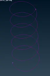
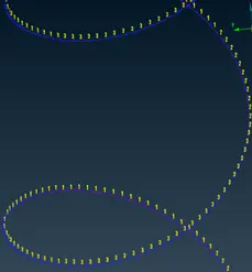
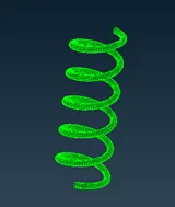
Fig: 1D representation of Spring
The last part involves the meshing of the side plate support on the lower mount. Here first we create a curve. First using edge2perimeter we create a line and the create curve using the cons2curve option. Then we will define that line as a seam line. We will do P1 and P2 selection of lower mount and support. We will select Overlap Shell to weld parallel faces. We will set search distance at 10 and give weld its PID. And create a weld connection. Once this is done mesh will not have a good flow. So will rearrange mesh flow in that region. To make sure, weld does not fail for the quality we split its elements to remove maximum length error.
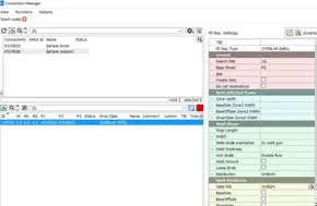
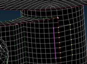
Fig: Welding of side plate on lower strut
- Mirroring of the suspension assembly
The suspension we have worked on is the half portion. This was done to save time. But once the meshing is done, we will mirror it and create other symmetrical half portions.
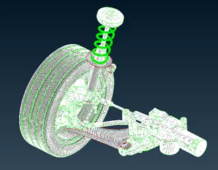
Fig: Half meshed portion of Suspension Assembly
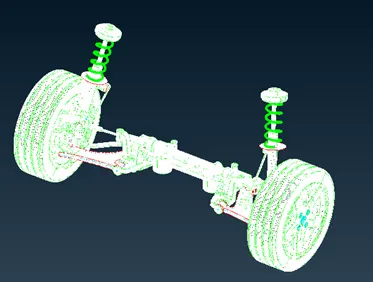
Fig: Suspension Assembly Mirrored
We go to the translate option, under transform we choose copy. We then go to the Symmetry option. We do the symmetry using the Mirror option.
Result:
- The 2 D meshing of the suspension side plate, wishbone and suspension lower mount is done using Mixed element meshing.
- The Volumetric meshing for the rest of the part is done using Unstructured Tria Element Meshing on the surface, Tetra Rapid, and Tetra FEM in the volume.
- Connections of bolts, welds, spring, and pendulum bar are deployed.
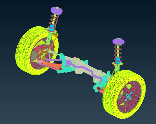
Fig: Suspension Assembly Meshing with Connection
Conclusion:
The meshing of the suspension assembly and the appropriate deployment of connection is done.