Week 11 - Final project
AIM:- To design and develop vehicles interior door trim with given Class-A surface along with master section. Also, Create the Side Attachment feature as per design rules.
OBJECTIVE:-
- Create thickened part using master section for reference
- Create the mounting features as per design guidelines in the industry and with master sections
- Apply material details :
- Draft analysis & Tooling analysis
- Creation of Pushpin.
INTRODUCTION:-
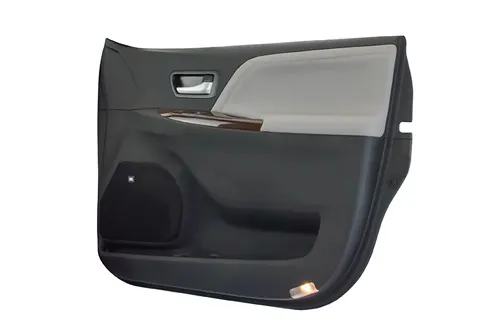
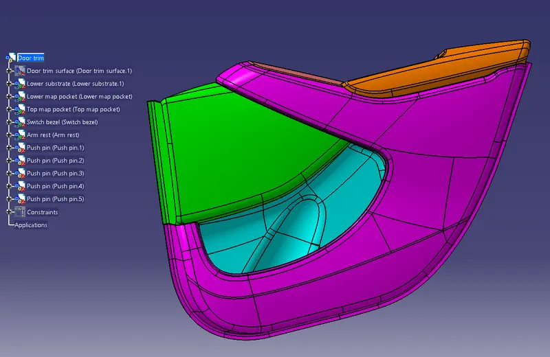
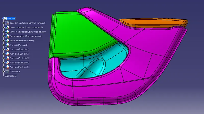
The door trim is the inner component of an automobile. Door trim consists of map pocket, armrest, carrier, lower substrate, and garnish. The other side of the door trim consists of engineering features like a dog house, push pin, switch bezel, and heat stake. Bellow is the image of the door trim.
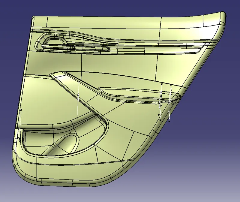
The input of class A surface:-
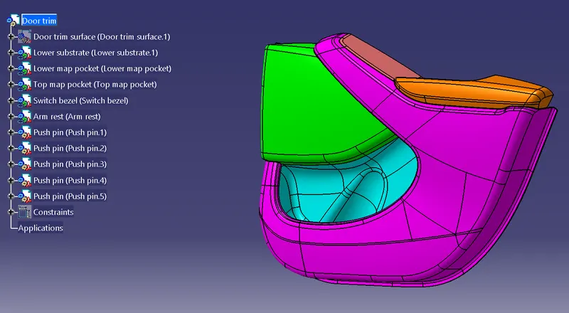
Different parts used indoor trim are:-
- Lower substrate
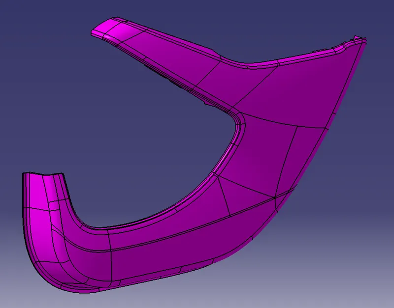
- Lower map pocket
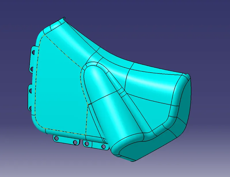
- Top map pocket
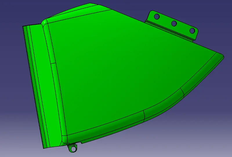
- Switch bezel
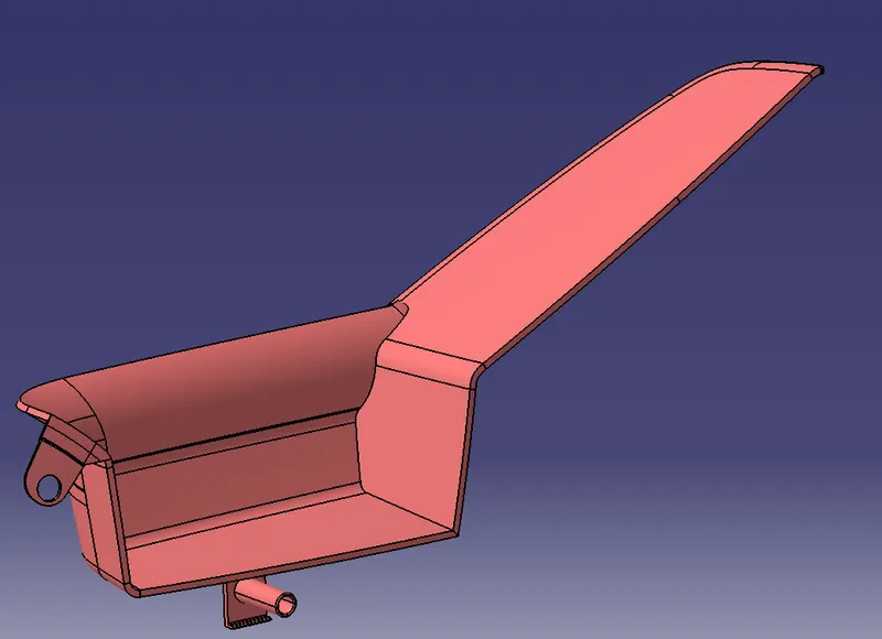
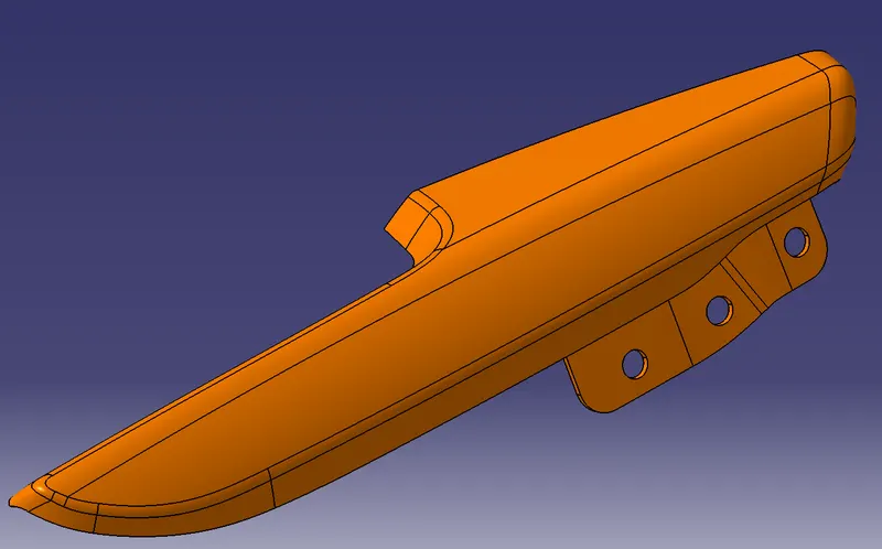
- Armrest
CONSTRUCTION:-
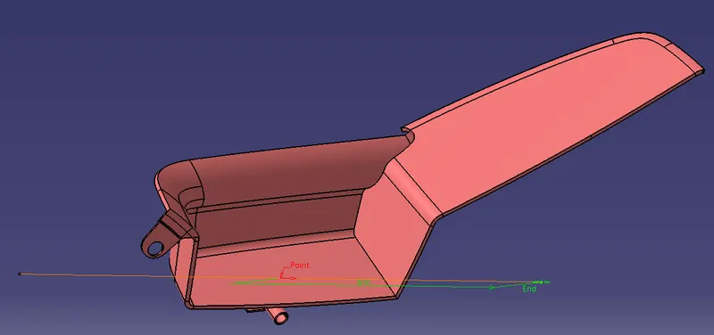
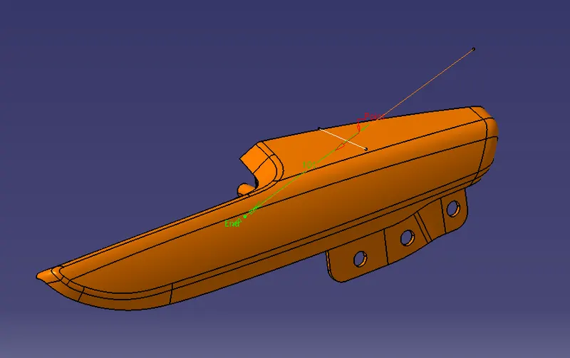
Tooling axis
The tooling axis is the axis in which the core and cavity open and close. in this case, the Y-axis is the natural tooling direction. The tooling axis of different parts of the door trim is given below.
- Lower substrate
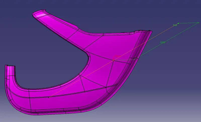
- Lower map pocket
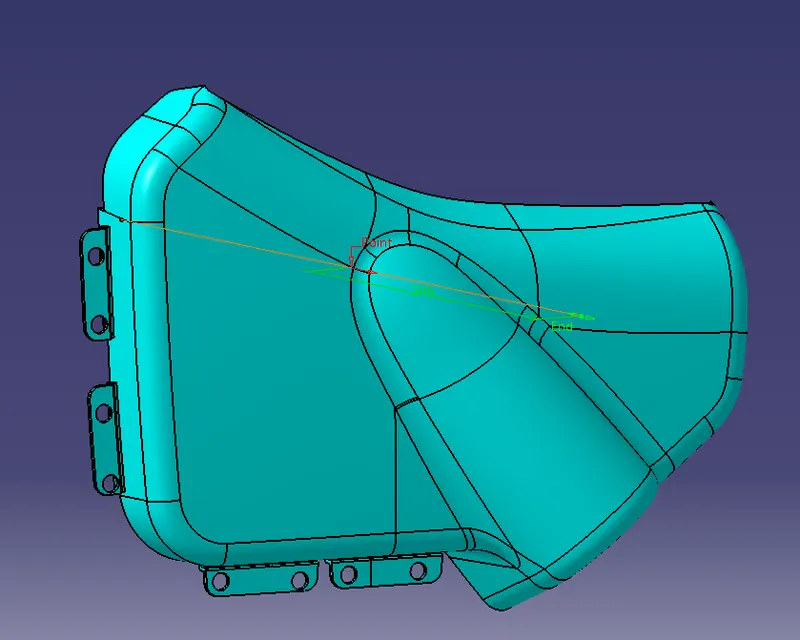
- Top map pocket
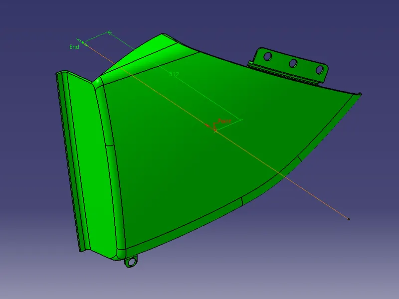
- Switch bezel
- Armrest
Draft analysis report on different Class-A surface
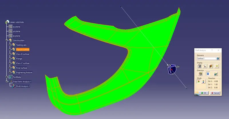
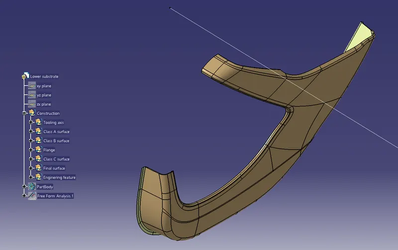
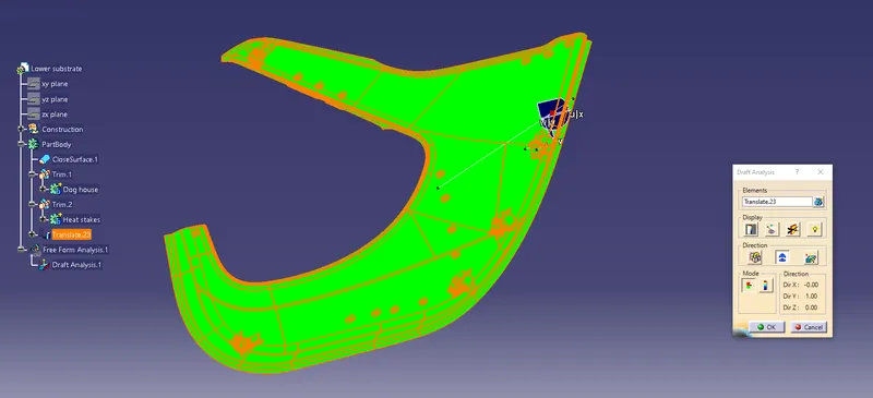
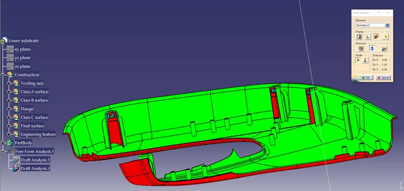
- Lower substrate draft analysis
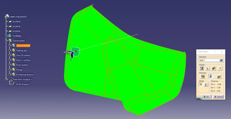
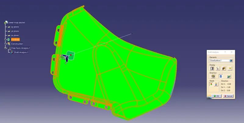
- Lower map pocket draft analysis
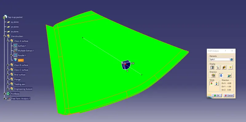
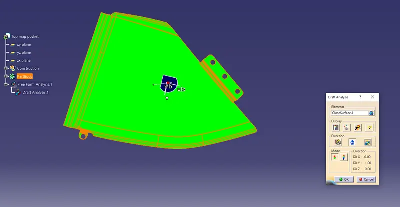
- Top map pocket draft analysis
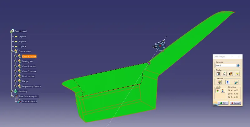
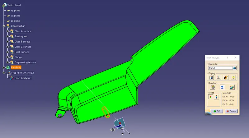
- Switch bezel draft analysis
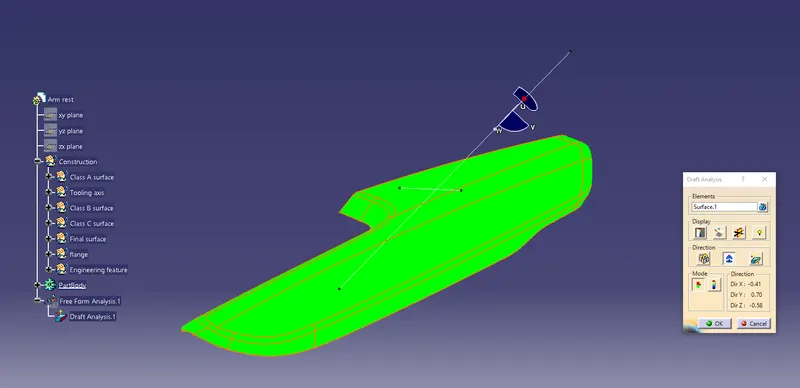
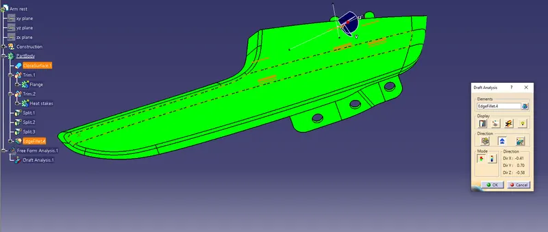
- Armrest draft analysis
Construction of Class-B surface
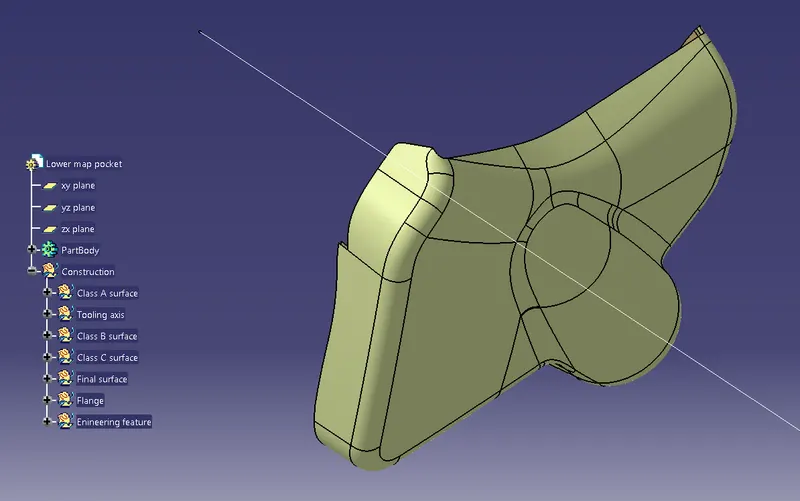
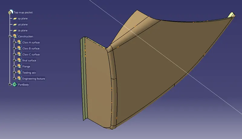
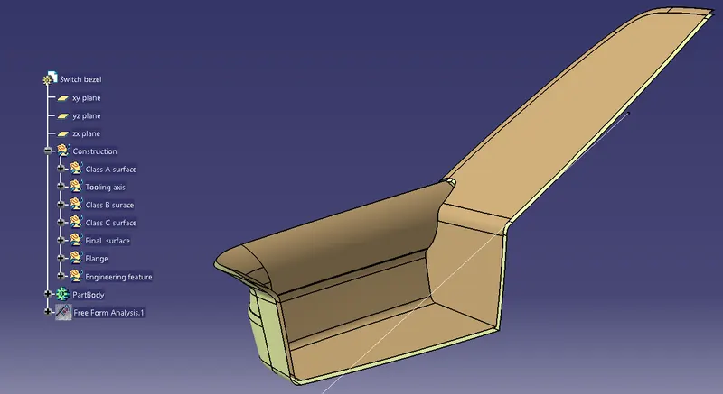
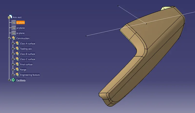
- Create a class-B surface by multi extracting the surface and then offset it at a distance of 2.5mm.
Lower substrate
Lower map pocket
Top map pocket
Switch bezel
Armrest
Construction of flange
Lower substrate flange
- To create the flange first extract the boundary where the flange should be created. Then sweep the boundary taking angle as 90 degrees.
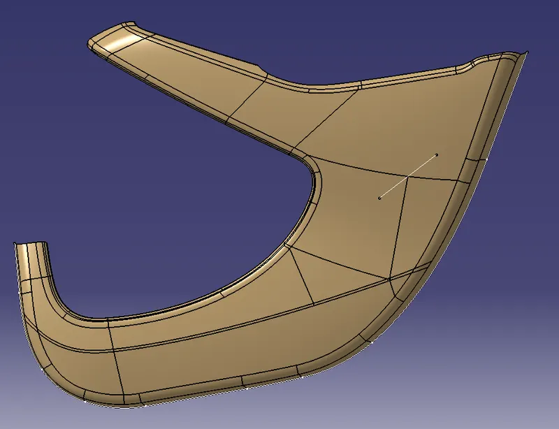
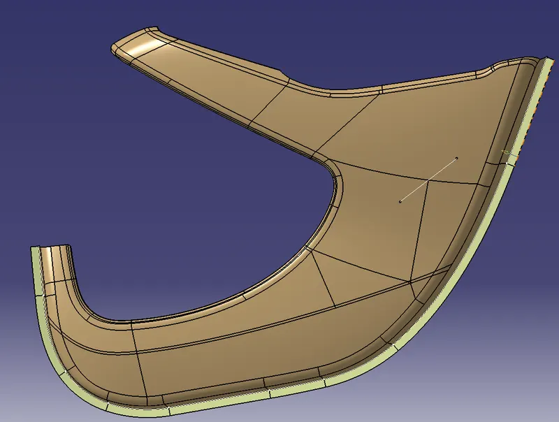
- Then join both the surface to create one surface and give the fillet value.
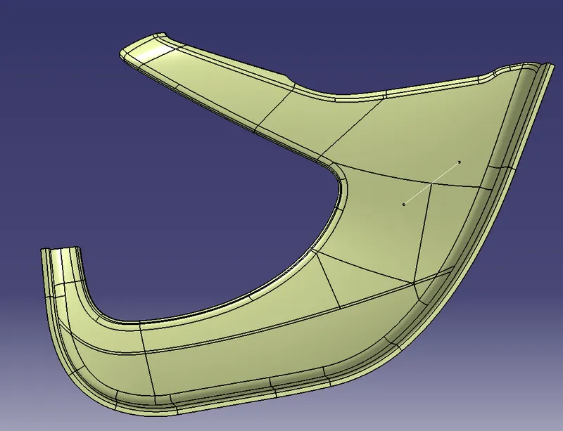
Top map pocket
- To create the flange first extract the boundary where the flange should be created. Then sweep the boundary taking angle as 90 degrees.
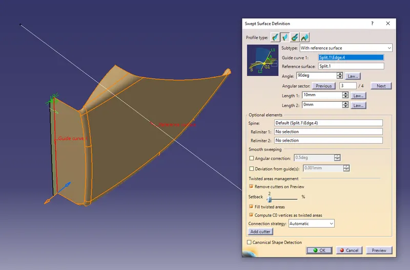
- Then join both the surface to create one surface and give the fillet value.
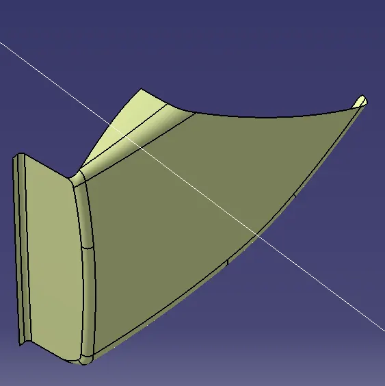
Construction of Class C surface
Class C surface is created by sweeping it along the tooling axis and sweeping it with reference surface with another part. Finally joined all the surfaces to create a Class-C surface.
Lower substrate
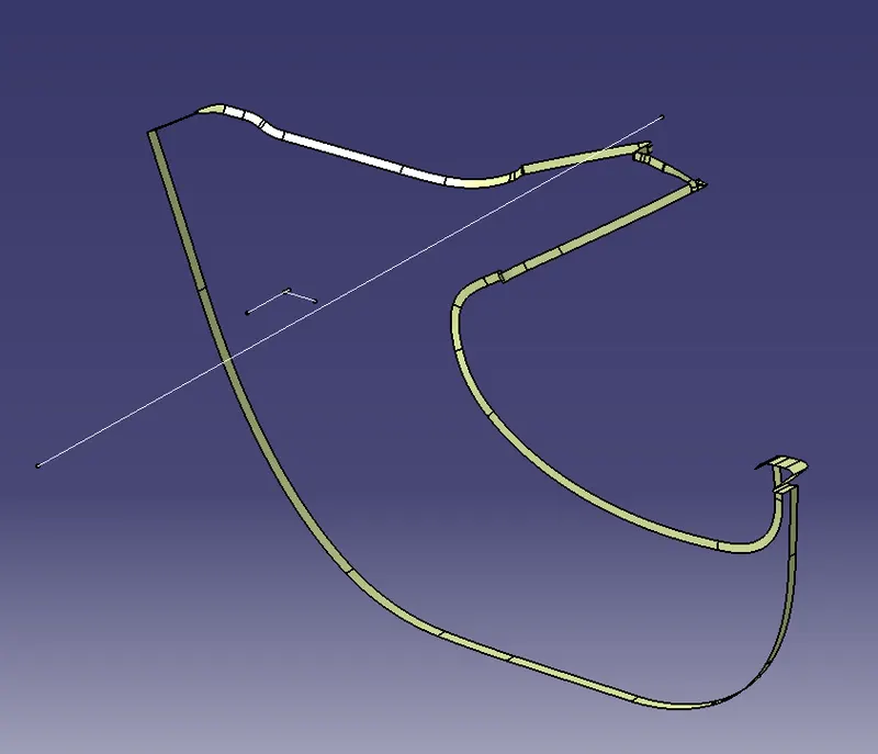
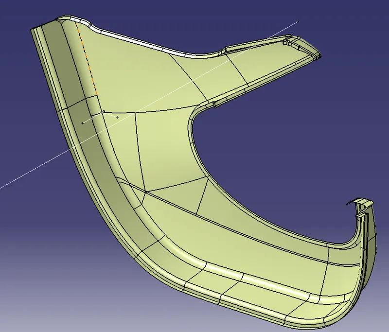
Lower map pocket
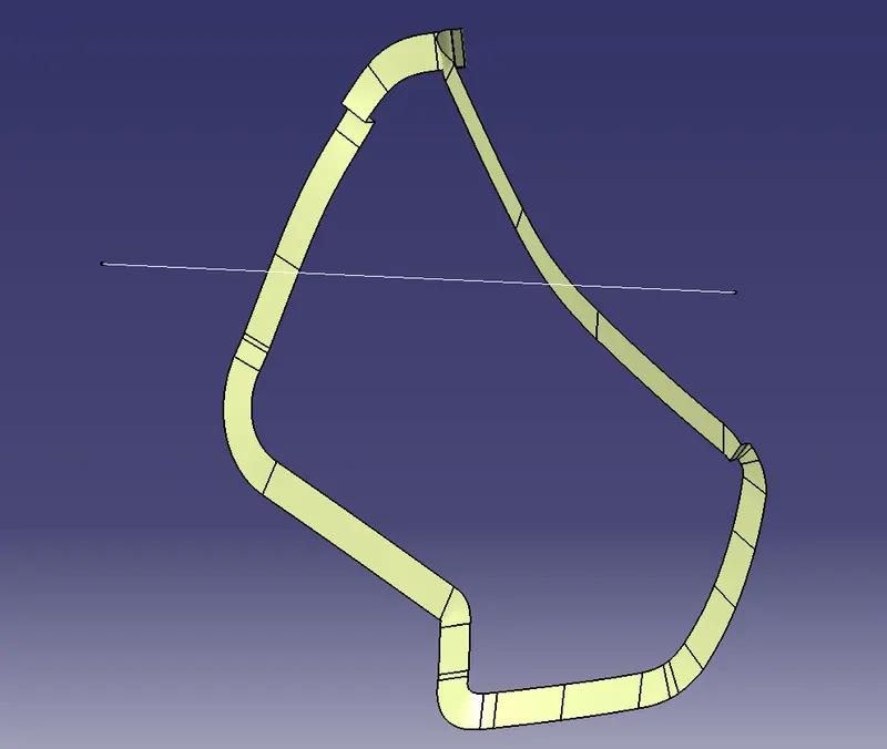
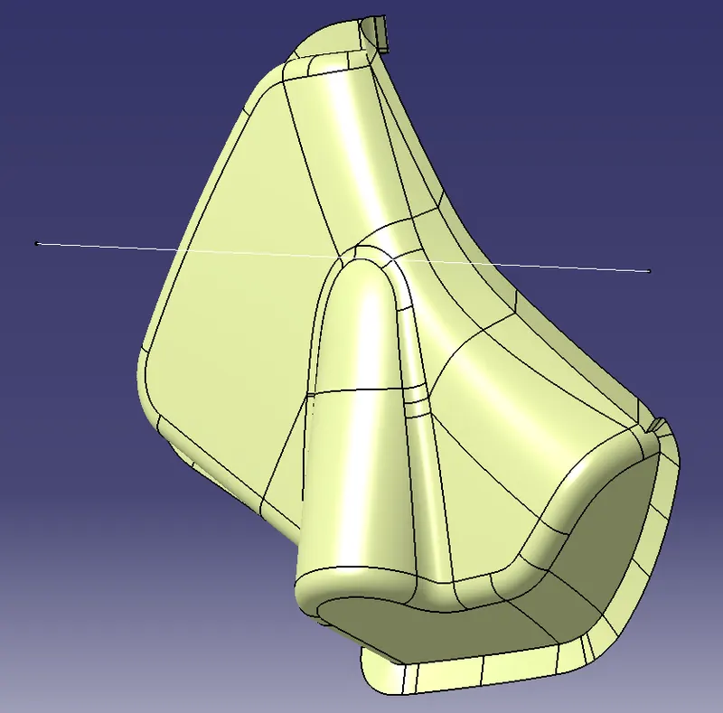
Top map pocket
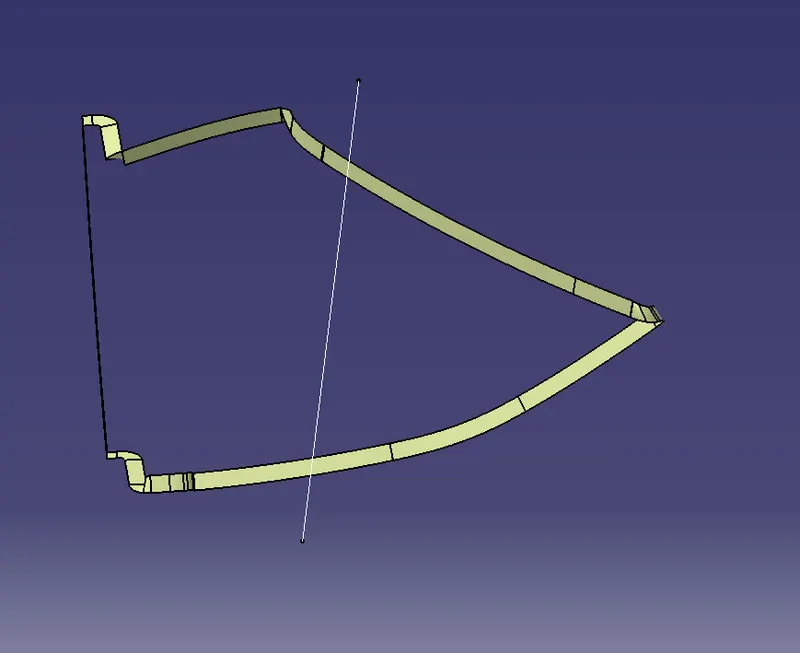
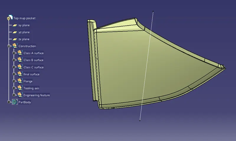
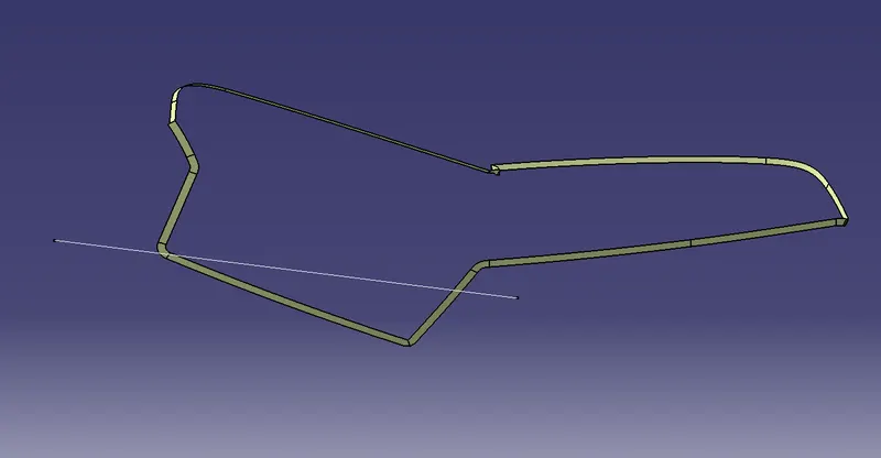
Switch bezel
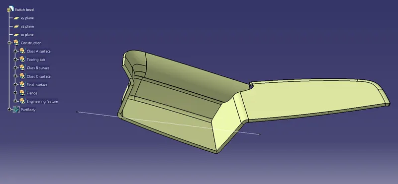
Armrest
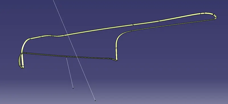
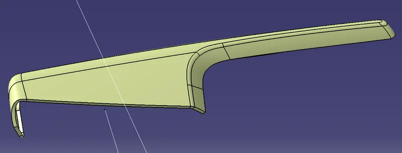
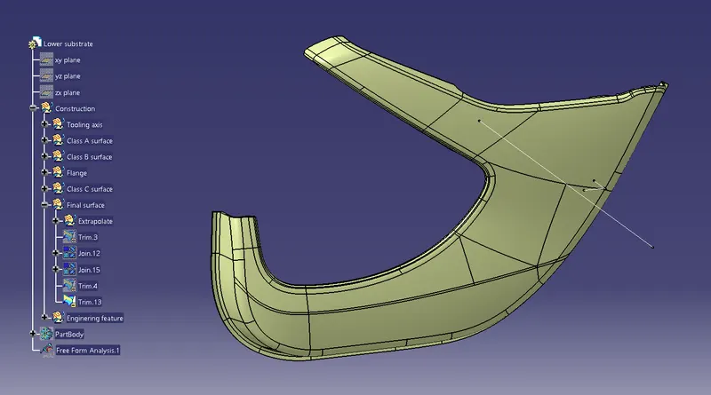
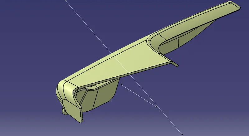
Finally Trim all the Class-A, Class-B, and Class-C surfaces to create the close body and then create the close surface.
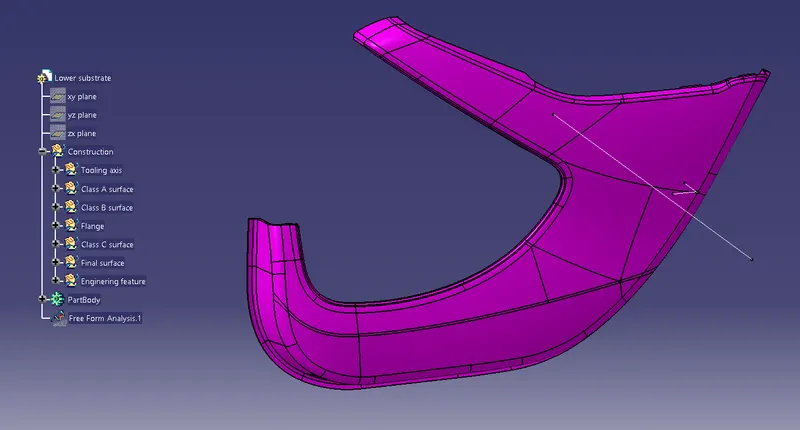
Lower substrate
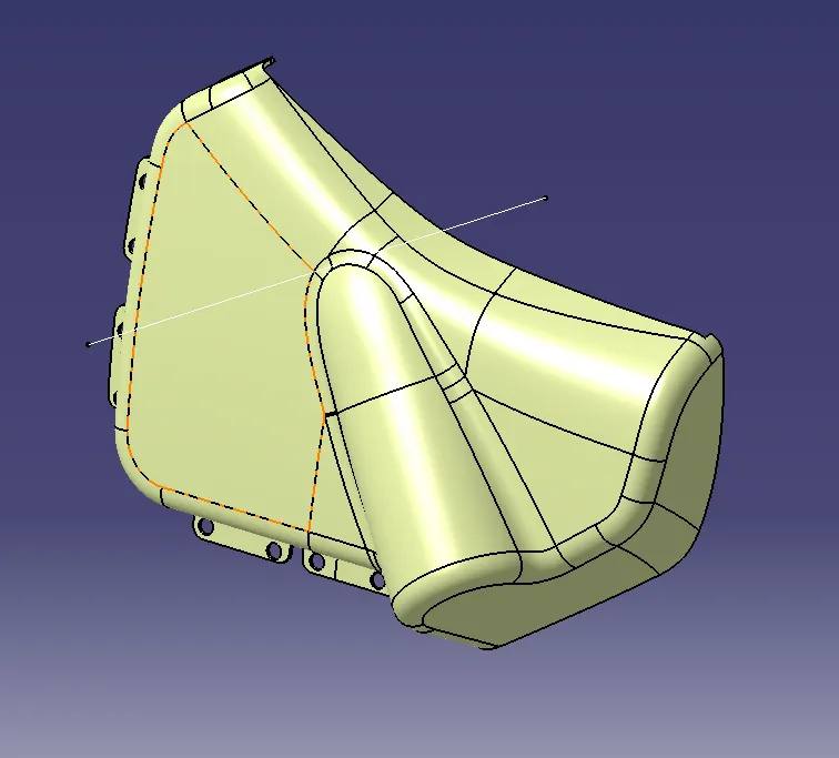
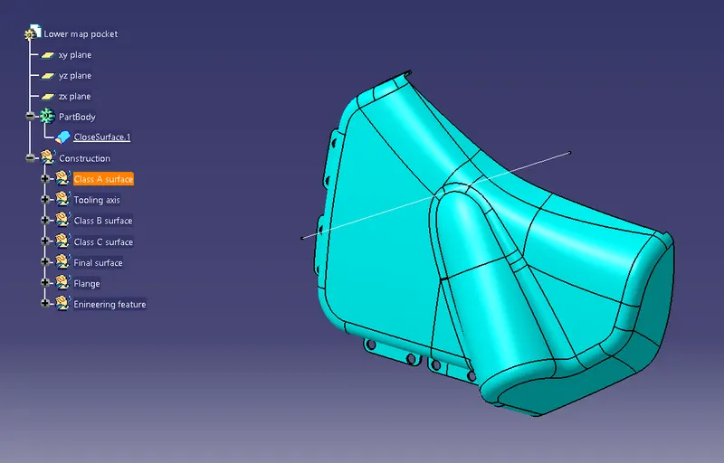
Lower map pocket
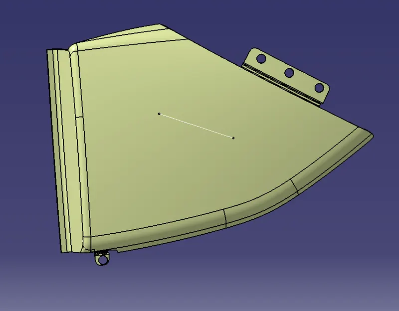
Top map pocket
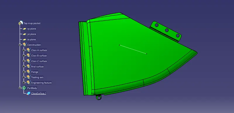
Switch bezel
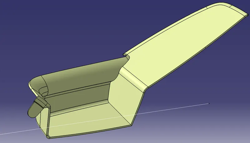
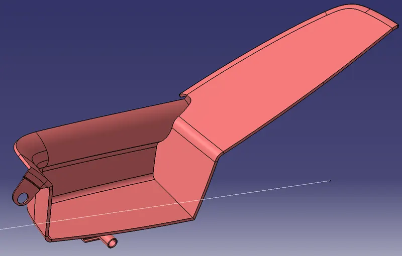
Armrest
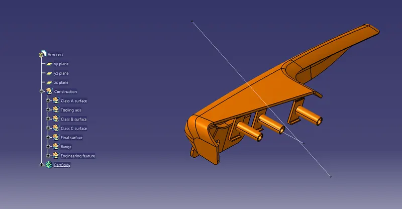
Construction of Attachment feature of the Door trim
Dog house
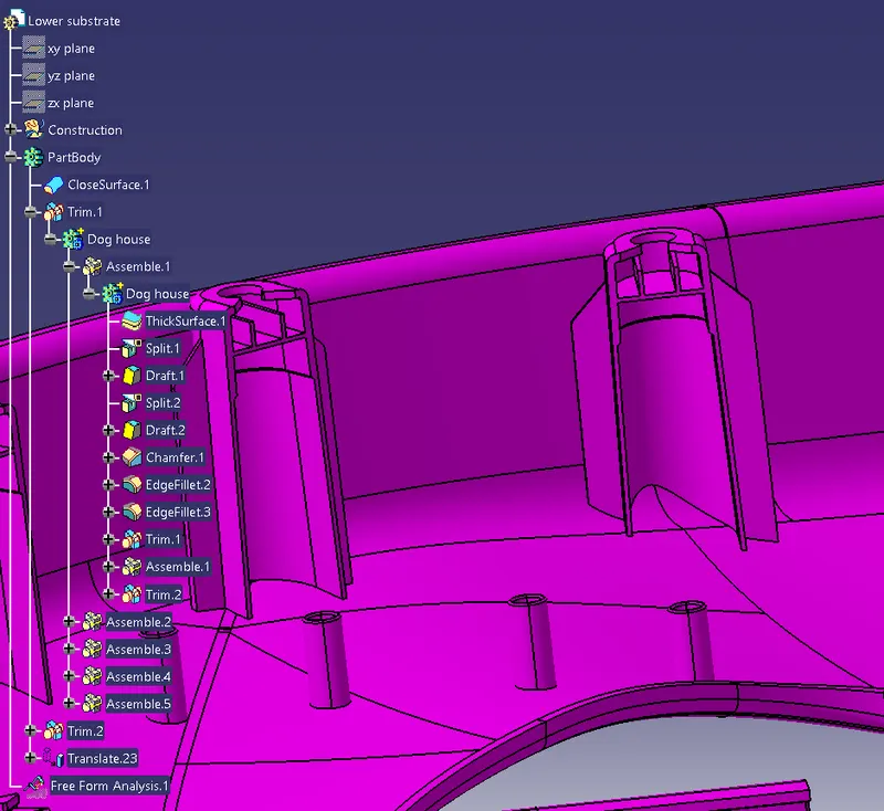
The dog house is an engineering feature used in the door trim. The primary function of the dog house is to avoid sink marks on the Class-A surface which may occur due to ribs on the Class-A surface. So the best possible solution is to increase the dog house height. We can create a dog house and make a screw boss above it in such a situation. We can also use them for making features that are perpendicular to the main tooling direction.
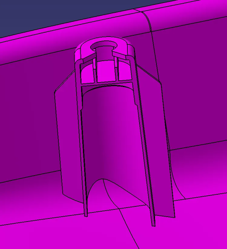
Design rule of Dog House
"C" is where the doghouse contacts the backside of the surface
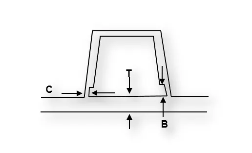
-
Doghouse wall thickness at the intersection of the part wall ( C ) should be 40% or less than the main wall stock ( T ).
-
Height of ( B ) should be between 3.0 – 6.0 mm
Construction
- First, create the sketch of the dog house
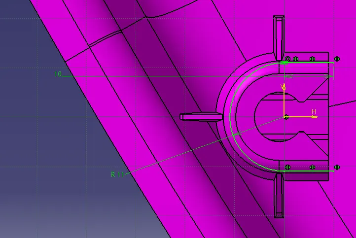
- Then sweep the sketch taking the draft direction as tooling axis.
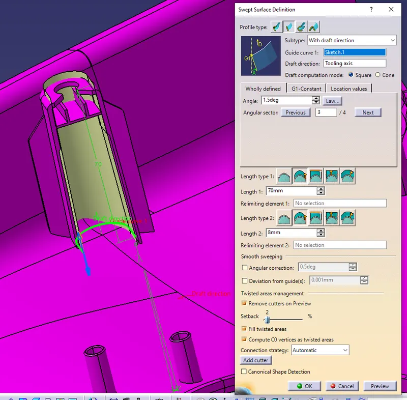
- Then extract the bellow surface and offset the surface. After offset, the surface trimmed both the surface.
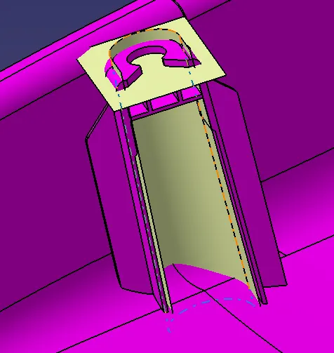
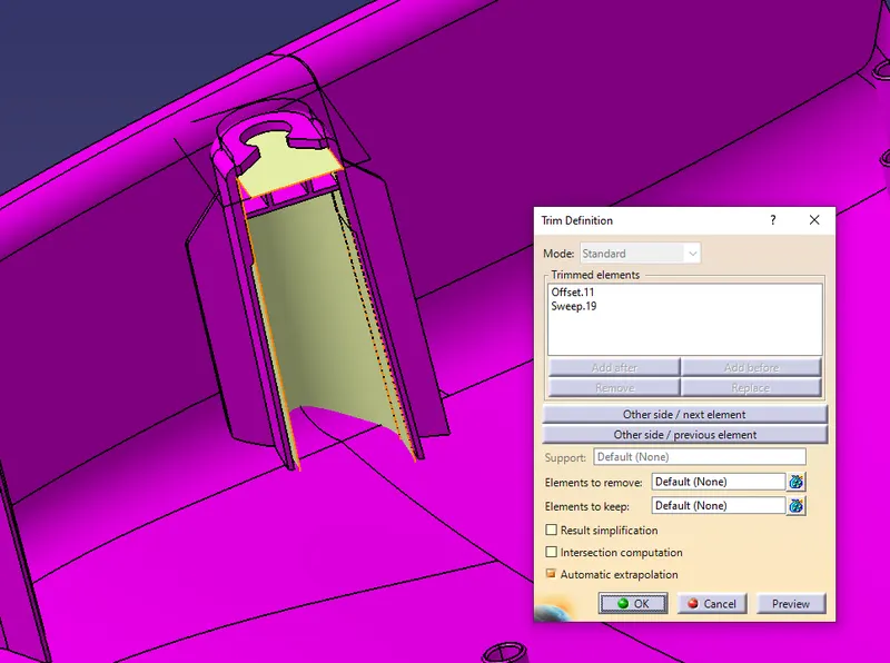
- Then trick the surface 2mm.
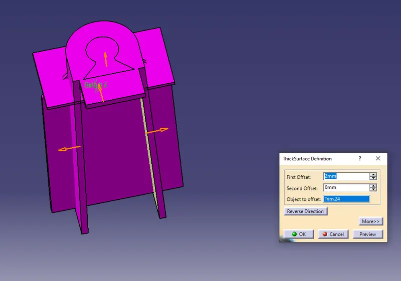
- Then create the surface and split the thick surface
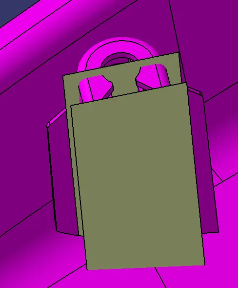
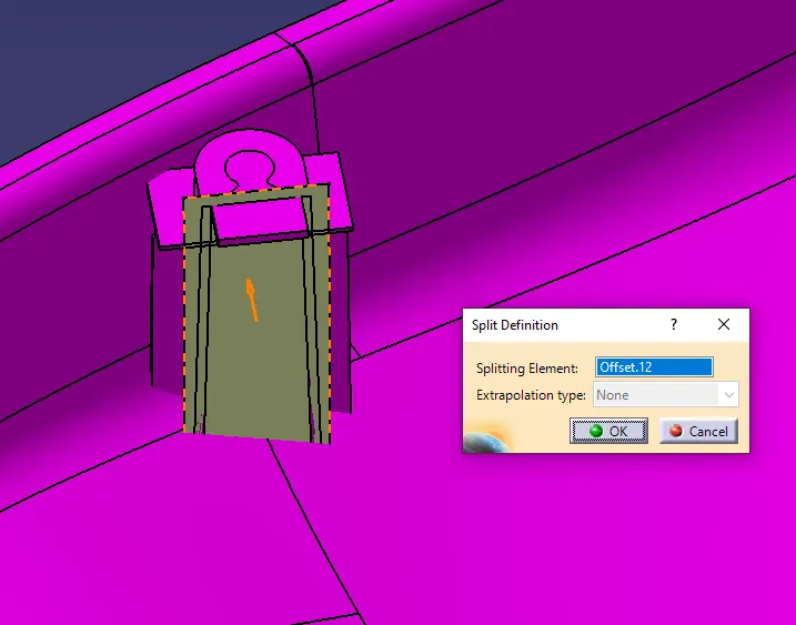
- Then draft the surface taking the pooling direction as tooling axis.
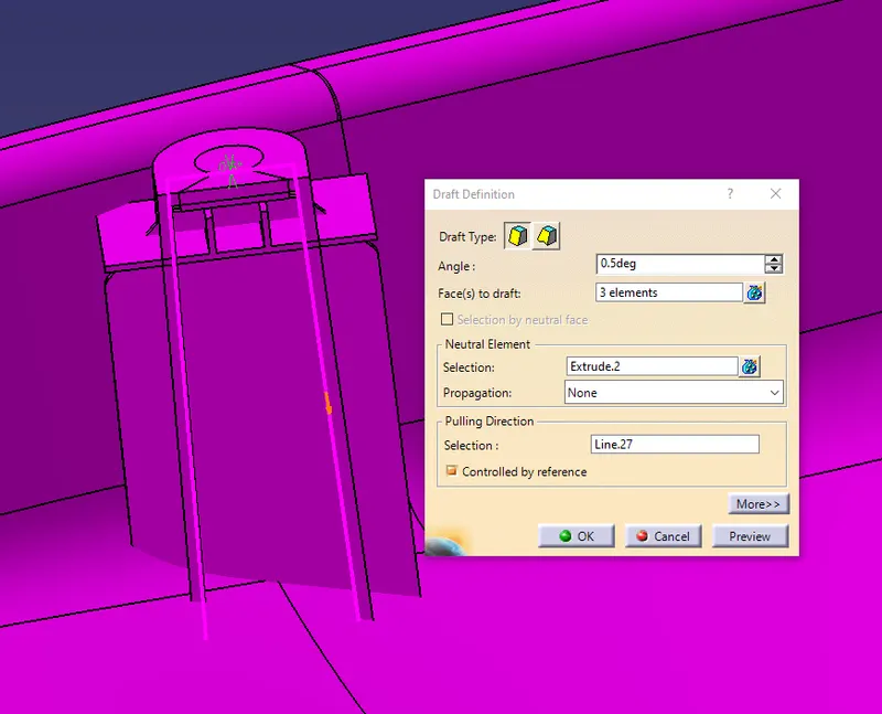
- Then create the bellow surface to avoid the sink mark in the Class-A surface.
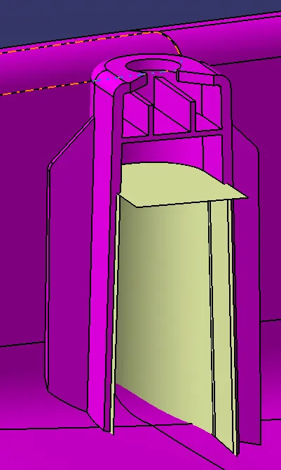
- After creating the surface then split the surface.
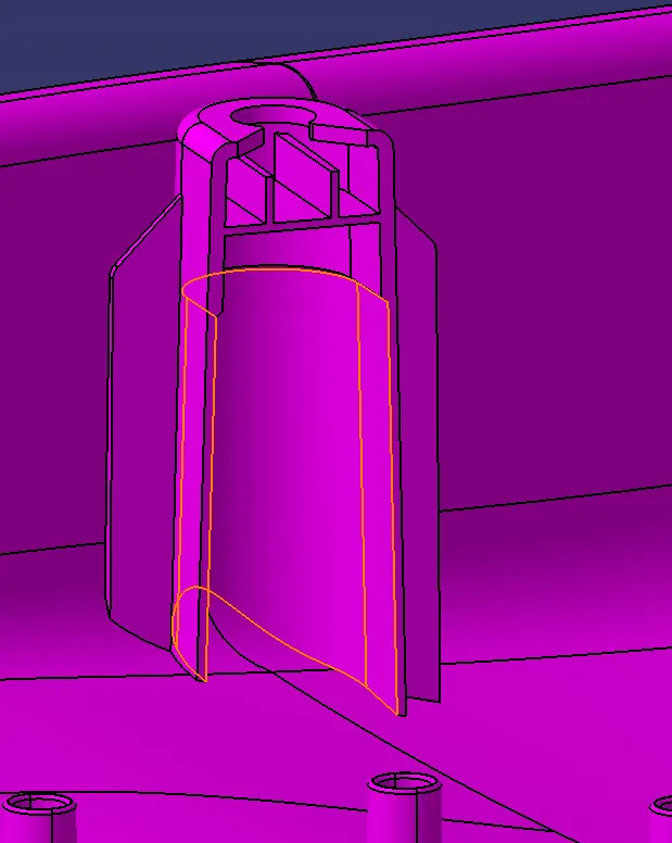
- Finally, create the sketch for where the Pushpin rest. Then pad the extruded surface.
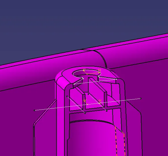
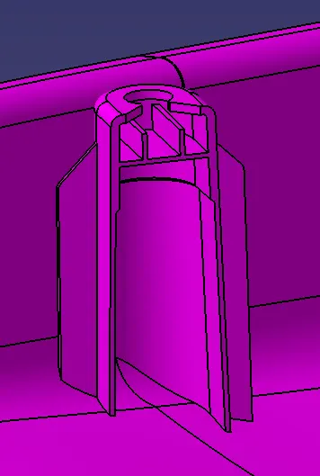
- Finally, give all the fillet and chamfer value to the dog house.
Heat stake
- First, create a sketch of the heat stake.
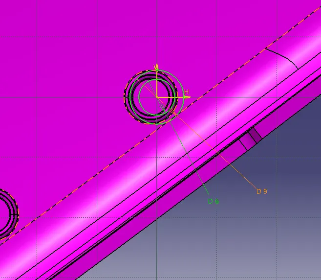
- Then create the pad of sketch and give the draft to heat stake taking the pulling direction as tooling axis.
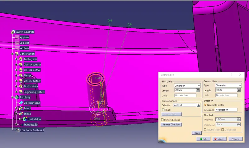
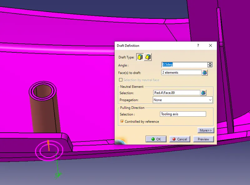
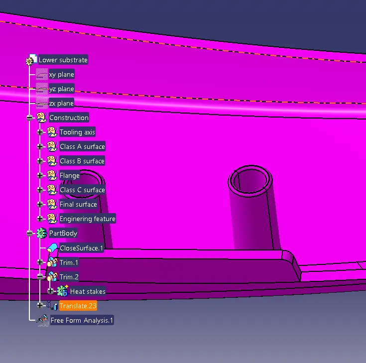
- Finally, give the fillet value.
Pushpin
- First, create a sketch of the pushpin.
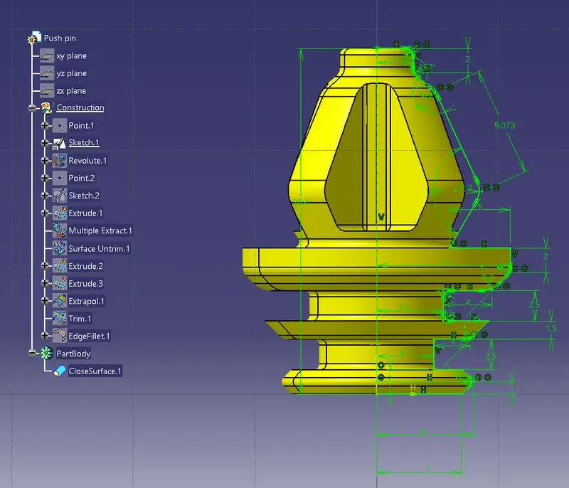
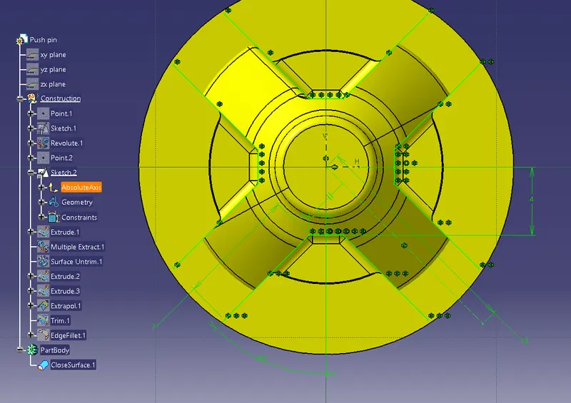
- Then revolve sketch 1 and extrude sketch 2.
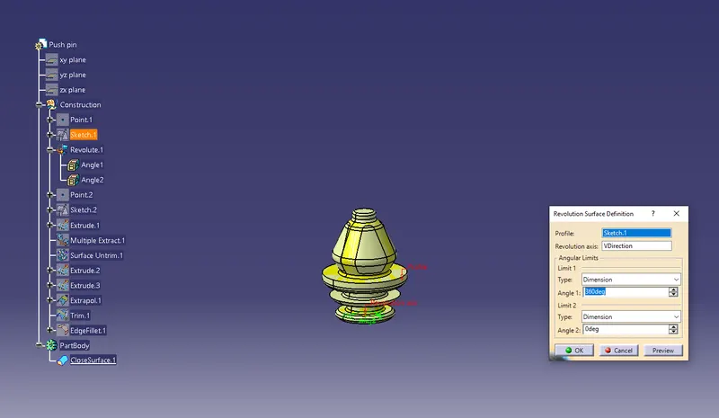
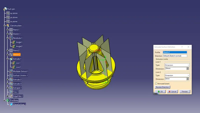
- Finally, trim both surfaces.
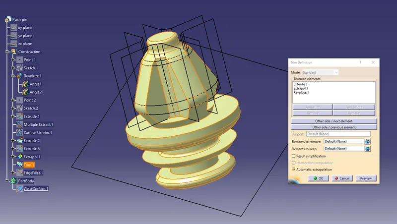
- Finally, give the fillet value to the pushpin.
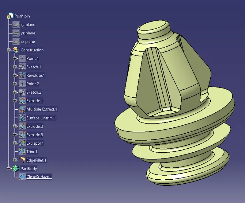
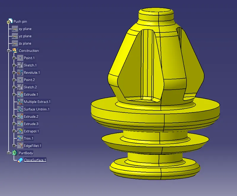
- Then give the close surface to the surface to create a solid part of a push pin.
DRAFT ANALYSIS:-
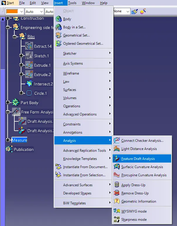
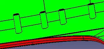
- First, change the view mode to material mode in the mesh.
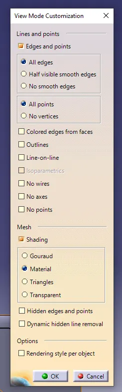
- Then go to insert>analysis>feature draft analysis
Lower substrate draft analysis
Lower map pock
Top map pocket
Switch bezel
Armrest
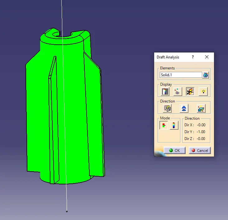
Dog House
- Main tooling axis draft analysis
- Side core tooling axis
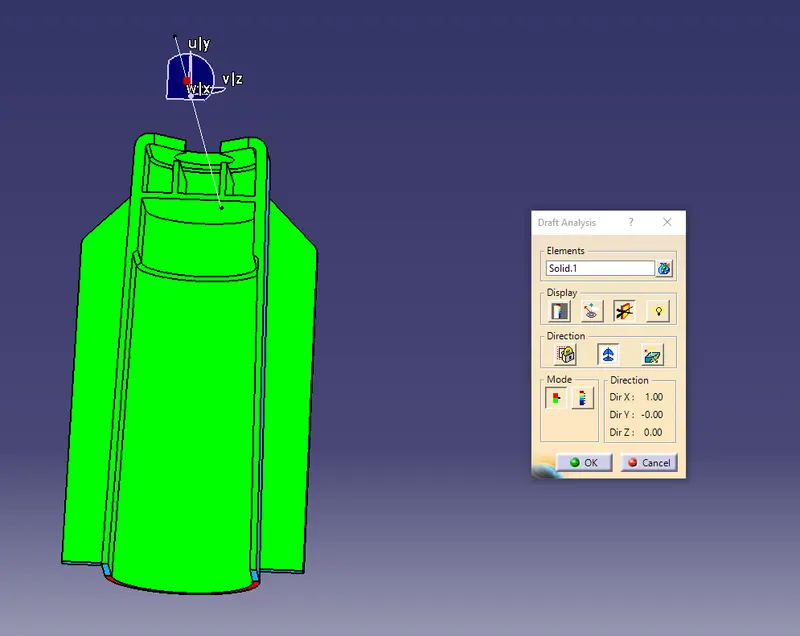
Screw boss
Different views of the Door trim panel
Isometric view
Front view
Top view
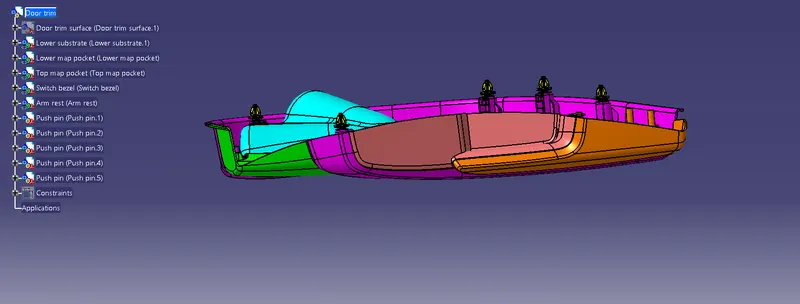
Side view
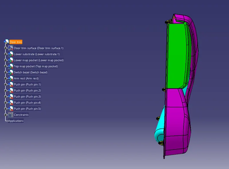
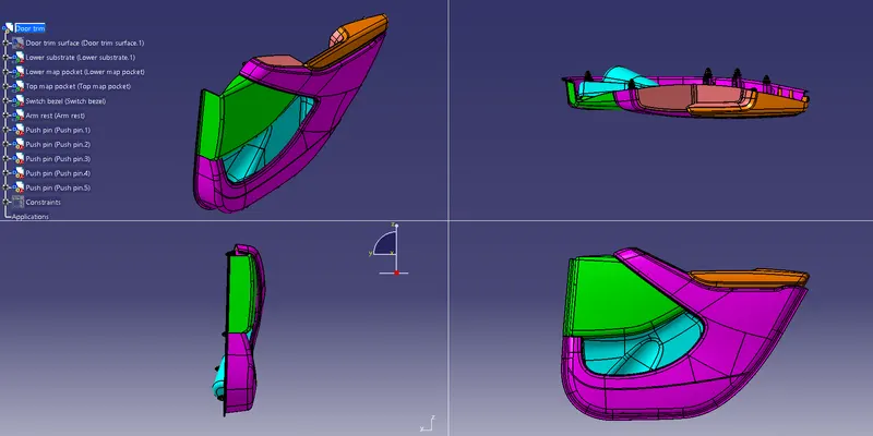
Multi-view