Roof challenge
AIM:- To design a Roof of the car from the given styling surface with consideration of all engineering aspects which are draft analysis for DFM, heat distortion, and snow load prediction to justify roof curvature.
INTRODUCTION:-
An automobile roof or car top is the portion of an automobile that sits above the passenger compartment, protecting the vehicle occupants from sun, wind, rain, and other external elements. Because the earliest automobiles were designed in an era of horse-drawn carriages, early automobile roofs used similar materials and designs.
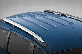
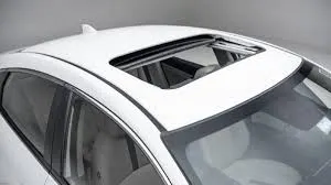
Different types of reinforcements that the car has are:-
- Front roof rail
- Bow roof rail
- Center roof rail
- Rear roof rail
Heat distortion criteria:-
Heat distortion temperature is the temperature at which the metal softens and deforms under a specific load. This study is done to check the ability of the roof to withstand high temperature with respect to the positioning of the reinforcements which contribute to increased strength.
Prediction formula
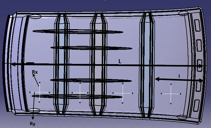
W = [1.73 x 10^(-3) x L] + [1.85 x 10^(-8) x (R^2)/t] + [ 1.10x10^(-3) x l] - 2.68
Judgment Condition: 2.7<W<3.5g
where
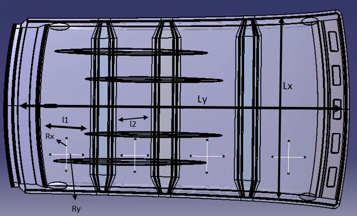
l = roof length X- direction in mm ( 0Y section)
R = Roof curvature
R =(Rx*RY)/(Rx+Ry)
Rx = X curvature
Ry = y curvature
t = Roof plate thickmess in mm
I = bow roof span in mm
Heat distortion table:-

All the values of "w" are within the limit, so the roof is passed in the heat distortion test.
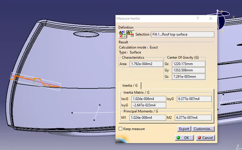
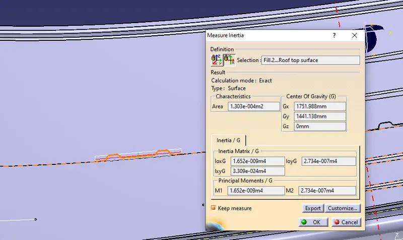
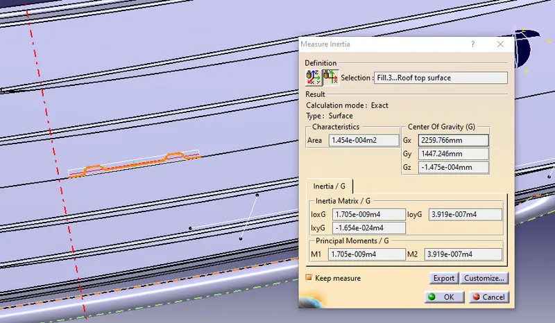
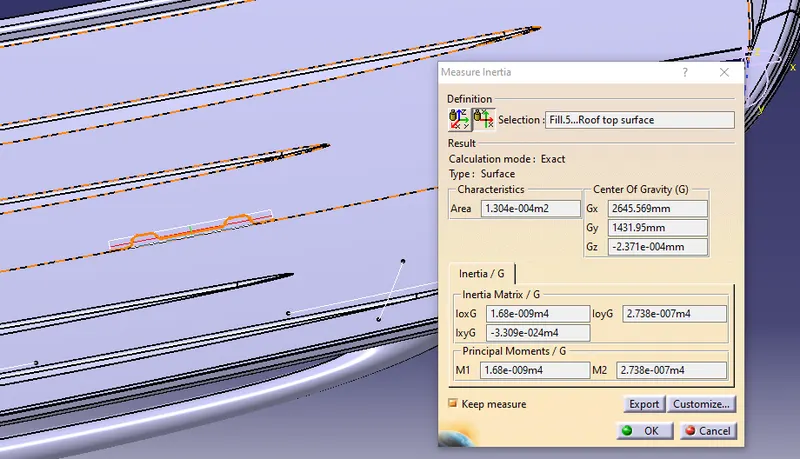
Moment of inertia:-
- Front roof rail
- Bow roof 1
- Center roof rail
- Bow roof 2
Snow load Test:-
The purpose of calculating snow load criteria is during the winter session there will be snowfall. snow may settle on the roof of the car when the snow is removed the roof should back to its original position. this is the purpose of doing snow load prediction. the snow load prediction gives a 95% correct value compared to the actual test. so it is obviously a number.
Calculation of snow load criteria for roof-
Snow load prediction value
Qr = [Iy x t ] / [α x s x [(Rx + Ry)/2] x 10 ]
Where
α = My x Lx x 10 , My = Y(Ly-Y)
Judgement condition = Qr ≥ 3.1
250 ≤ s ≤ 380
t =Roof plate thickness in mm
Ly = Distance between the front roof rail and rear roof rails on the vehicle along with 0Y [mm]
Lx = Distance between left and right end of the roof on the roof bow in mm
width of the roof panel exposed on the surface
Y =Distance between front roof rail to roof bow in mm
s = distance for which roof bow bears divided load in mm
s =L1/2+L2/2
ly =Geometrical Moment of inertia of roof bow [y cross - section] in mm^4
Rx =Lateral direction curvature radius of roof panel Y cross-section on roof Bow in mm
Roof panel curvature radius of the length Lx in front view
Ry = Longitudinal direction curvature radius of the roof X cross-section on roof bow in mm
Snow load table:-

Roof
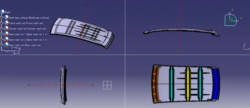
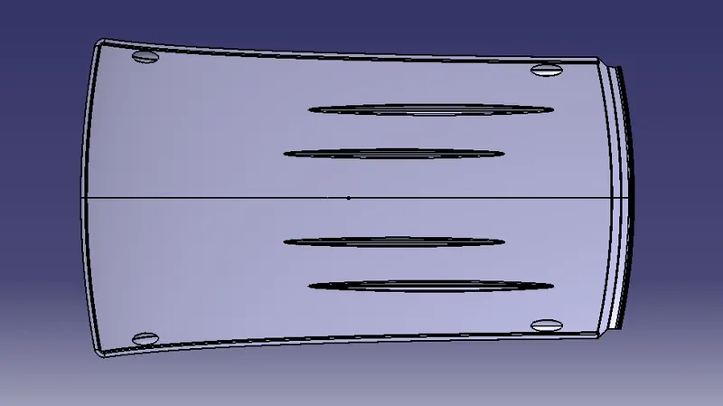
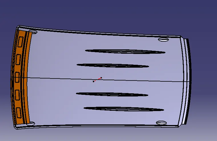
Below is the image of the roof front and bottom view.
Bottom view
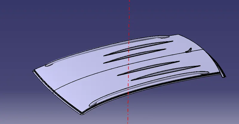
Isometric view
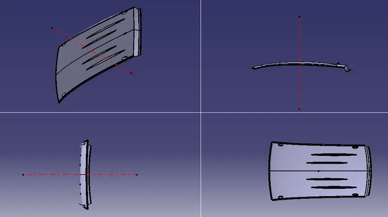
Multi-view
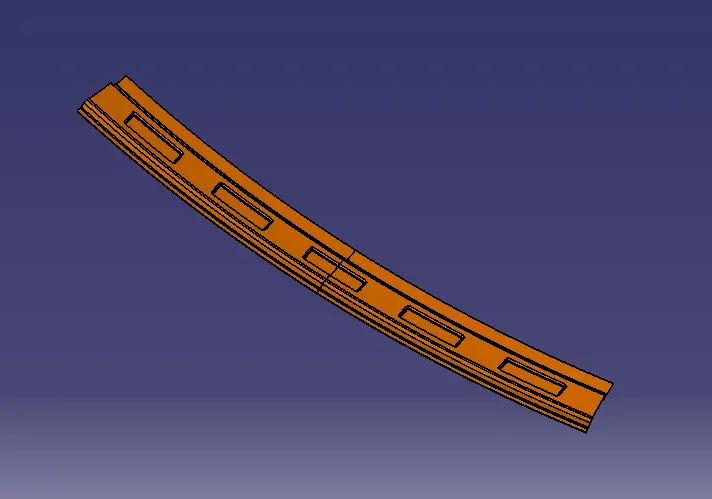
Front roof rail
- The front roof rail is the one that joints the front roof side and the bodyside front.
- The front-most end is joined by spot weld and the backside will be joined by the mastics.
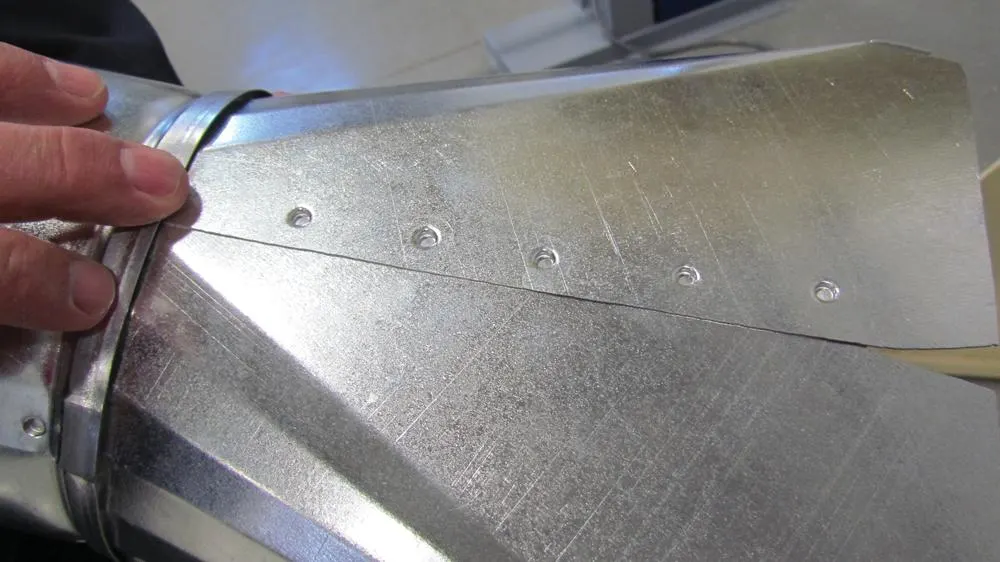
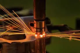
Spot weld:-
Spot welding is a type of electric resistance welding used to weld various sheet metal products, through a process in which contacting metal surface points are joined by the heat obtained from resistance to electric current. The process uses two shaped copper alloy electrodes to concentrate welding current into a small "spot" and to simultaneously clamp the sheets together. Work-pieces are held together under pressure exerted by electrodes. Typically the sheets are in the 0.5 to 3 mm thickness range. Forcing a large current through the spot will melt the metal and form the weld. The attractive feature of spot welding is that a large amount of energy can be delivered to the spot in a very short time. This permits the welding to occur without excessive heating of the remainder of the sheet.
Mastic joint:-
Mastic in automotive sheet metal is generally used to bond two different sheet metals by using additives and sealant. it is very helpful to reduce vibration between the sheet metal part.
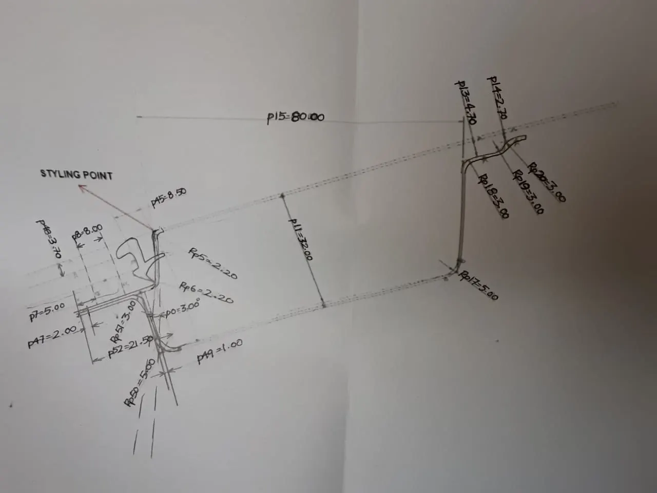
FRONT ROOF RAIL
Master section of the front roof rail
Below is the image of the front roof rail placed with the roof.
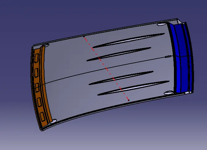
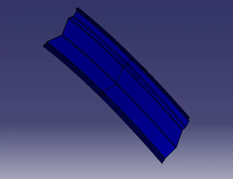
REAR ROOF RAIL:- Rear roof rail is the one that joins the back door and the bodyside outer.
Master section of the rear roof rail
Below is the image of the front roof rail and rear roof rail placed with the roof.
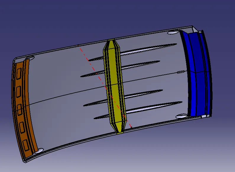
CENTER ROOF RAIL
Master section of the center roof rail
Below is the image of the front roof rail, the rear roof rail, and the center roof rail placed with the roof.
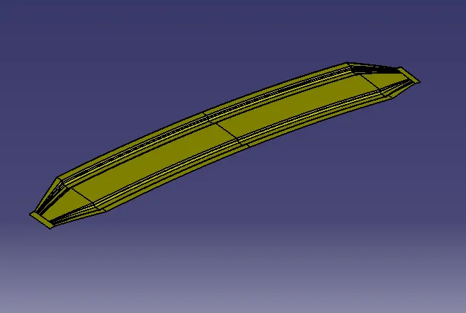
BOW ROOF RAIL:- The bow roofs are given to improve the torsional stiffness and load-bearing capacity of the roof structure. The number of bow roofs presents depends on the overall size of the roof. Presently in this project, two bow roofs are added.
Bow roof rail 1
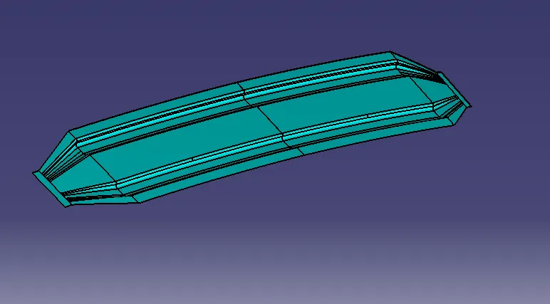
Bow roof rail 2
Below is the image of the front roof rail, the rear roof rail, the bow roof rail, and the center roof rail placed with the roof.
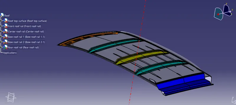
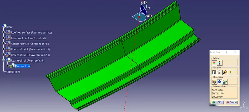
Draft analysis:-
- Roof
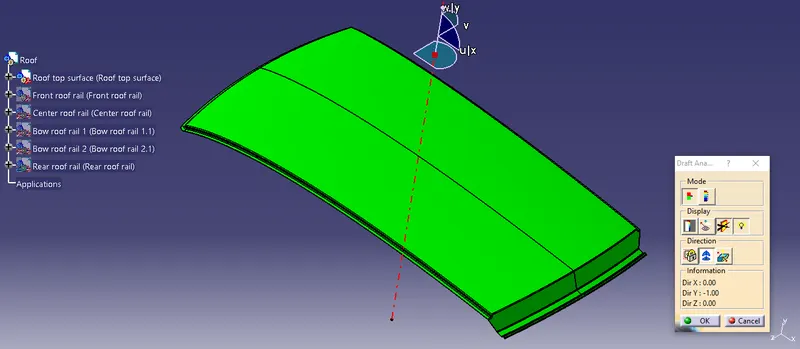
- Front roof rail
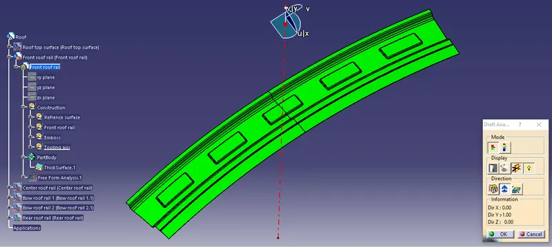
- Bow roof rail 1
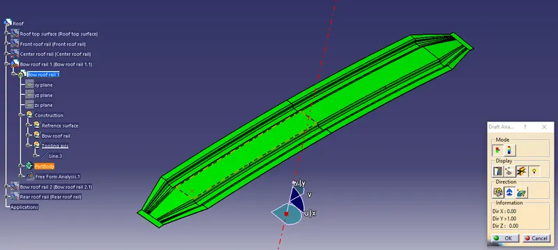
- Bow roof rail 2
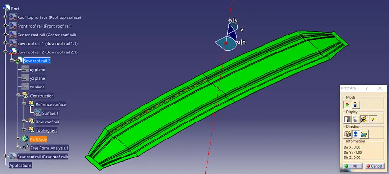
- Center roof rail
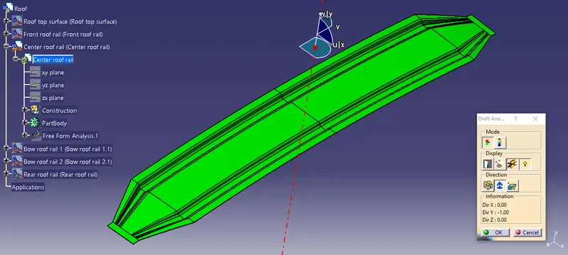
- Rear roof rail
Multi-view of roof:-