Week 8 - Challenge 2 - Base Bracket Design
AIM:- Create the Base Bracket Plastic component through the given Class-A surface. To begin with, the tooling axis for the given Class-A Surface should be created meeting the requirements of the draft angle and at the end perform the Draft analysis on the model.
OBJECTIVE:-
- Create Tooling Axis
- Perform a draft analysis on Class-A surface
- Creation of Class-B and Class-C surface
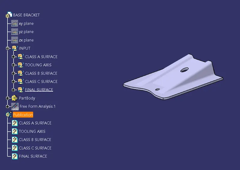
- Creation of the proper tree structure
- Publishing the Tooling Axis and Class A, B, and c surface.
PROCEDURE:-
1) First check the connectivity of the Class-A surface by using the boundary condition.
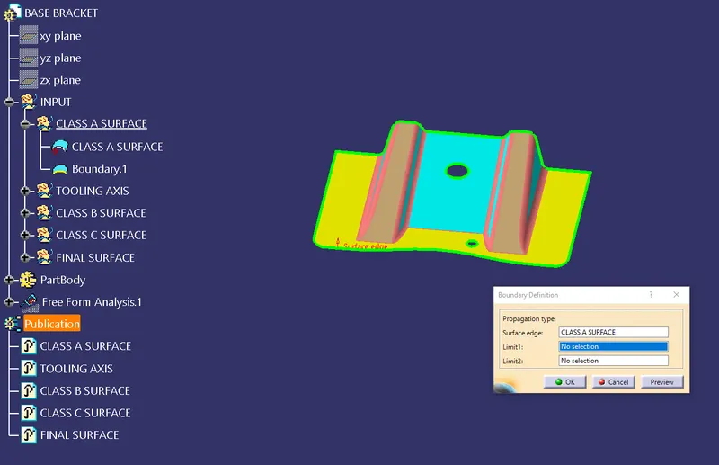
2) TOOLING AXIS:-
- Create a point on the center of the hole. Select the point and direction, create a dummy tooling axis.
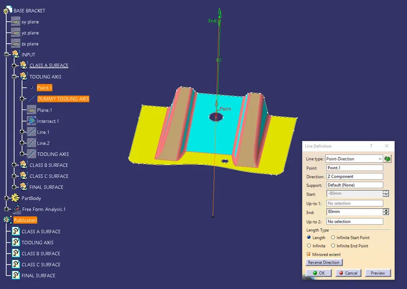
- Then in yz plane create an intersection on the surface.
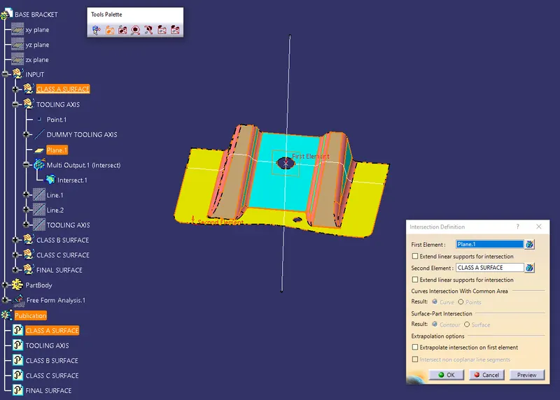
- Then check which all surfaces can create a problem in Class-A surface.
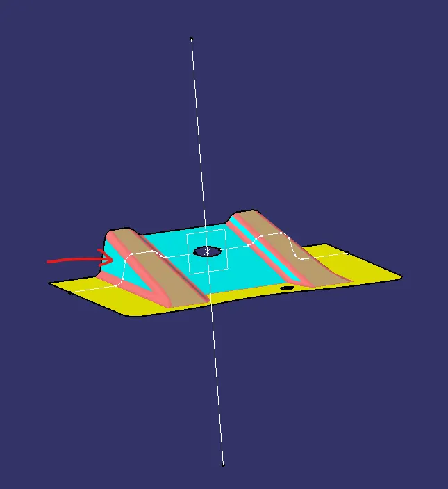
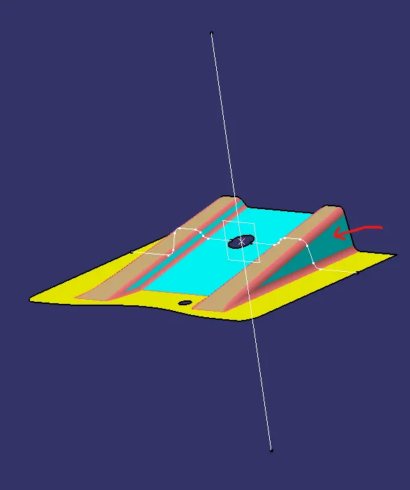
- These two surfaces can also create a problem but both the surface is at an angle of 45° along the axis.
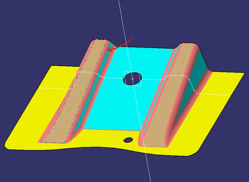
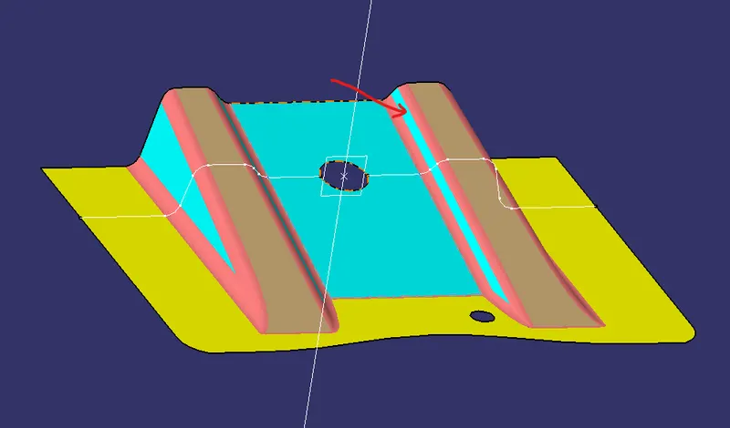
- Create a line by selecting the two-point.
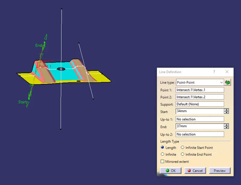
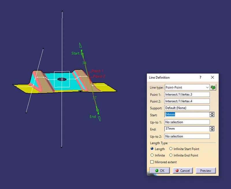
- Bisect both the line to create the tooling axis.
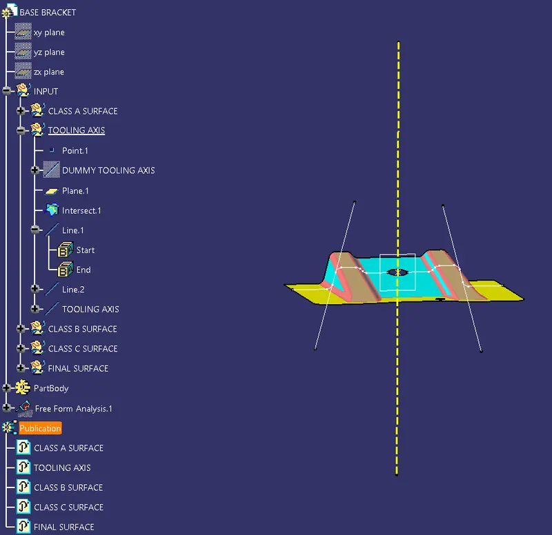
3)CLASS-B SURFACE:-
i) RIB 1
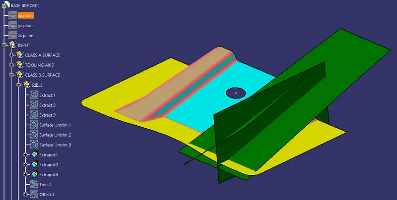
- First, extract the surface from the Class-A surface.
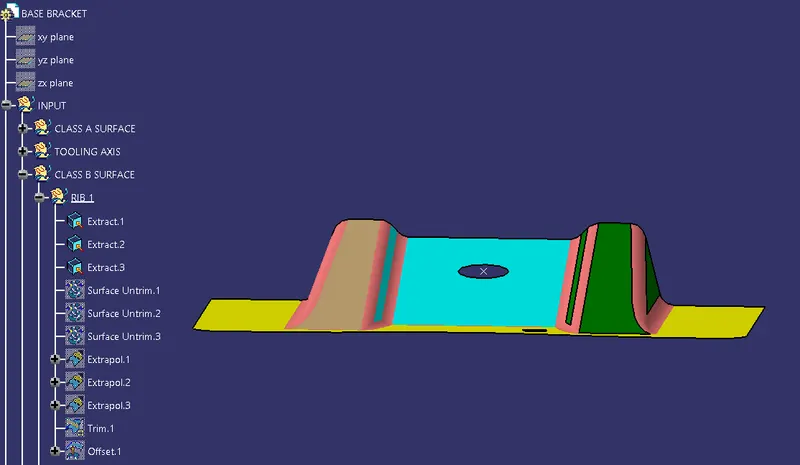
- Then surface untrim and extrapolate all the surface.
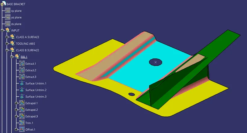
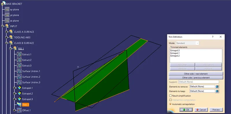
- Trim all three surfaces to attain the proper surface.
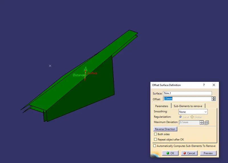
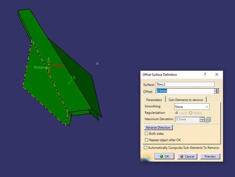
- Offset the trim surface at a distance of 2.5 mm.
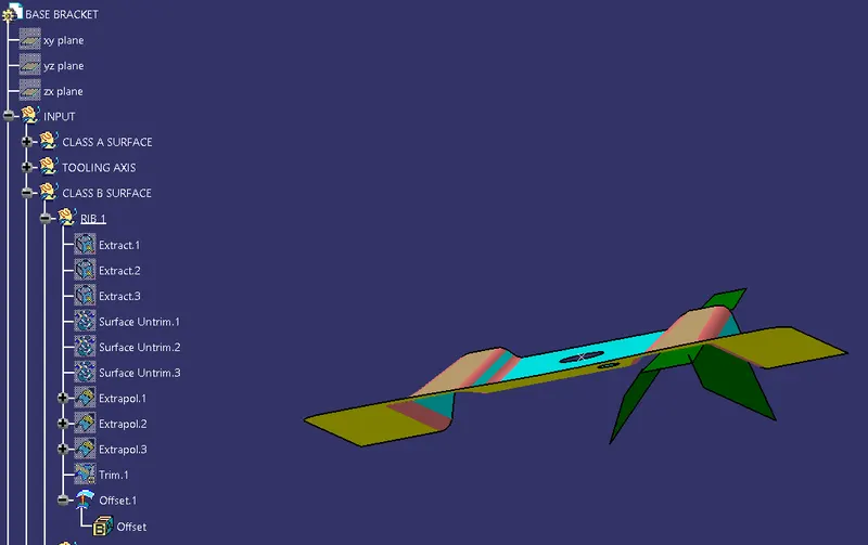
- The Bellow image is the final rib 1 surface.
ii) RIB 2
-
First, extract the surface from the Class-A surface.
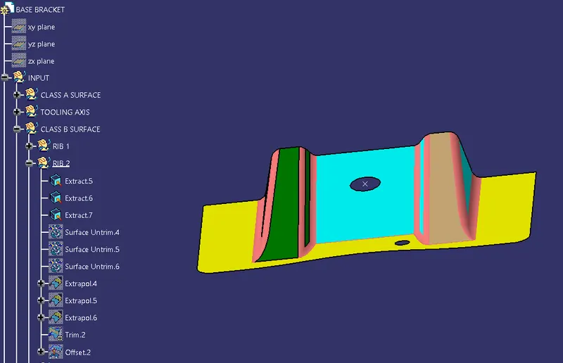
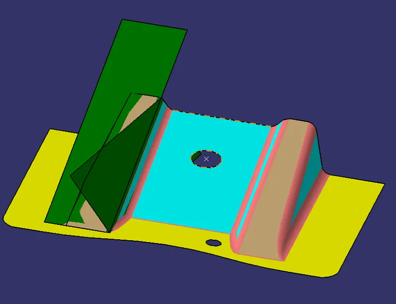
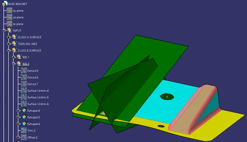
- Offset the trim surface at a distance of 2.5 mm.
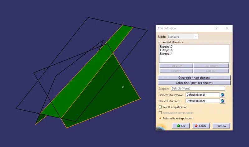
- Offset the trim surface at a distance of 2.5 mm.
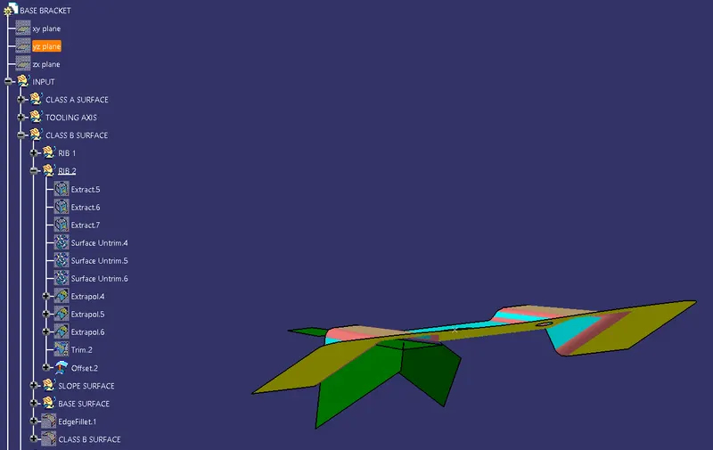
- The Bellow image is the final rib 2 surface.
iii) SLOPE SURFACE
-
First, extract the surface from the Class-A surface.
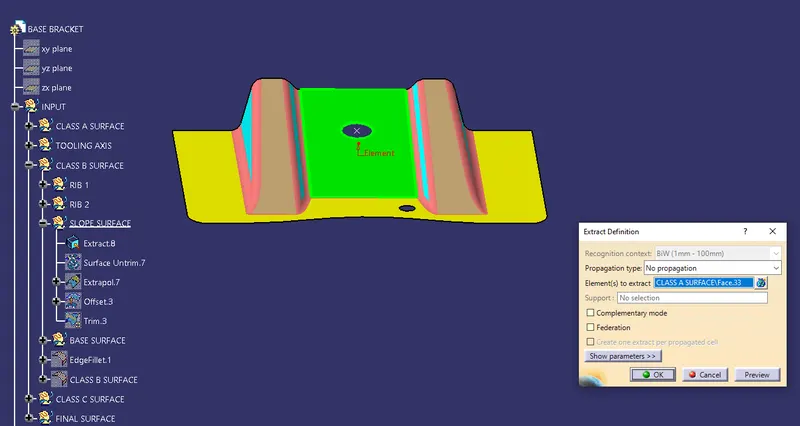
- Then surface untrim and extrapolate all the surface.
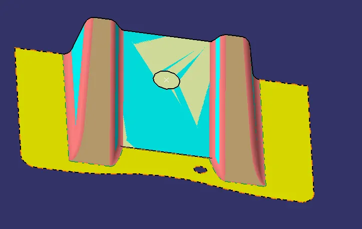
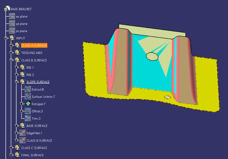
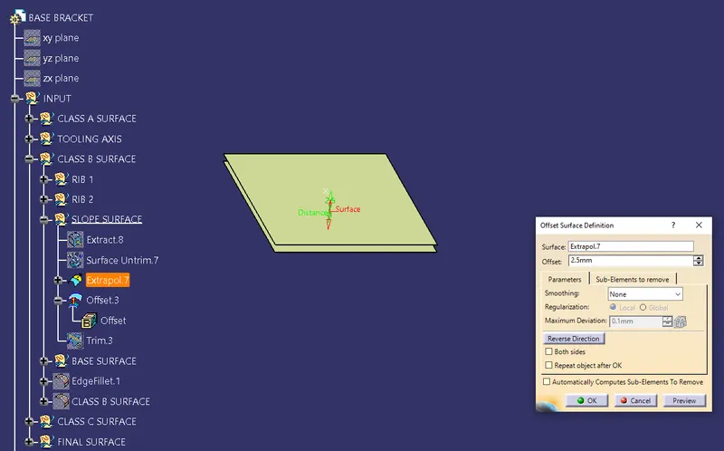
- Offset the trim surface at a distance of 2.5 mm.
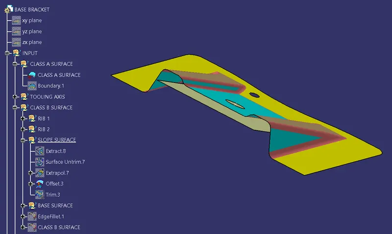
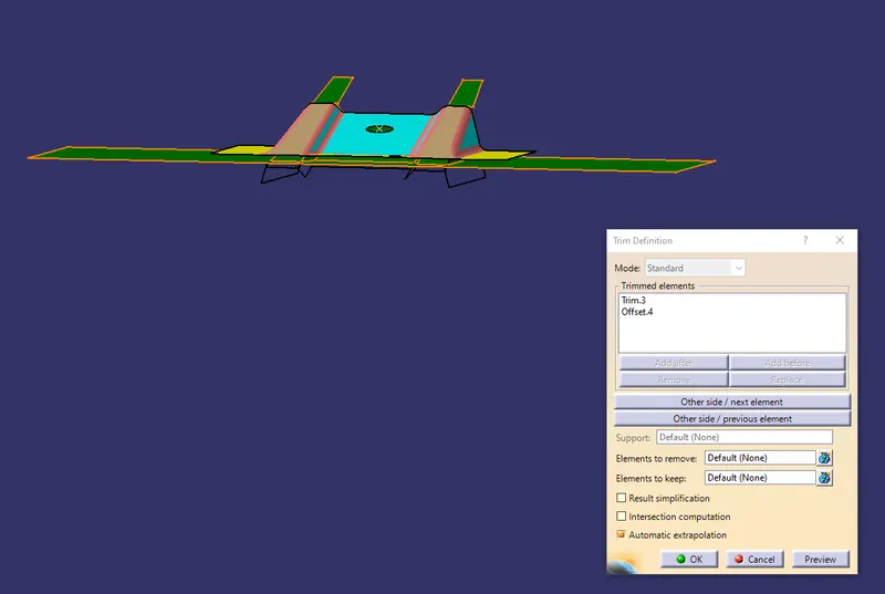
- Trim the slope surface with rib 1 and rib 2.
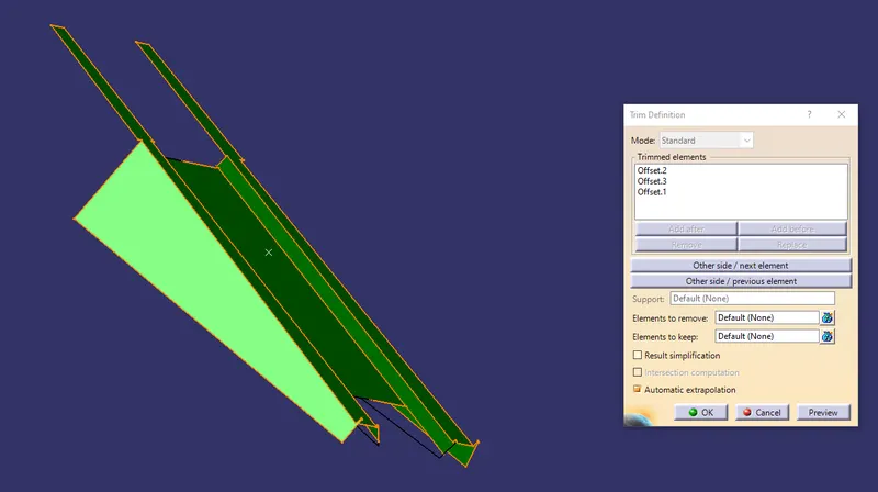
- The Bellow image shows the final trim of rib 1, rib 2, and slope surface.
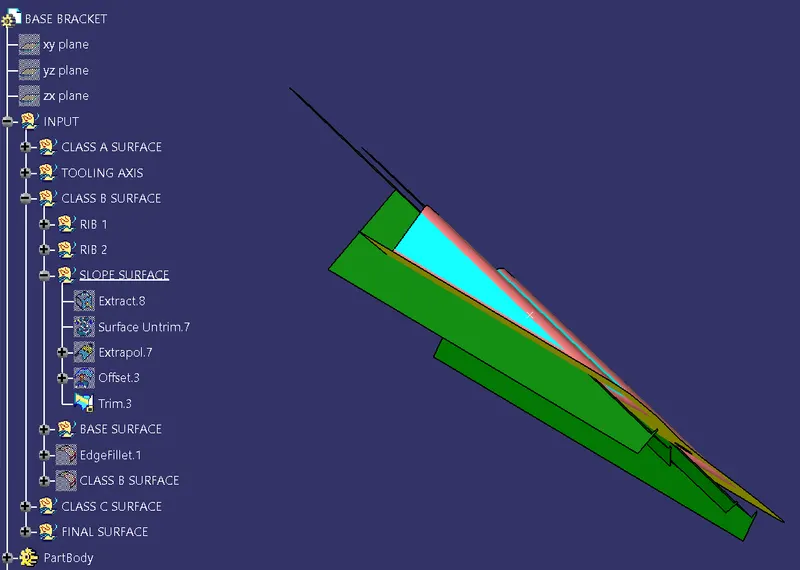
iv) Base Surface
- First, extract the surface from the Class-A surface.
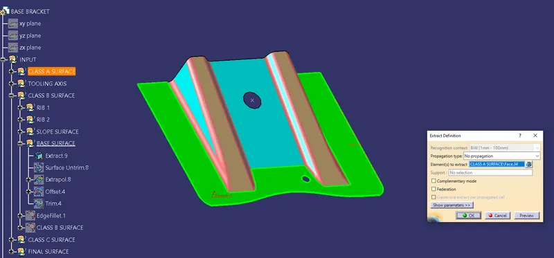
- Then surface untrim and extrapolate all the surface.
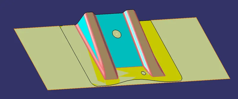
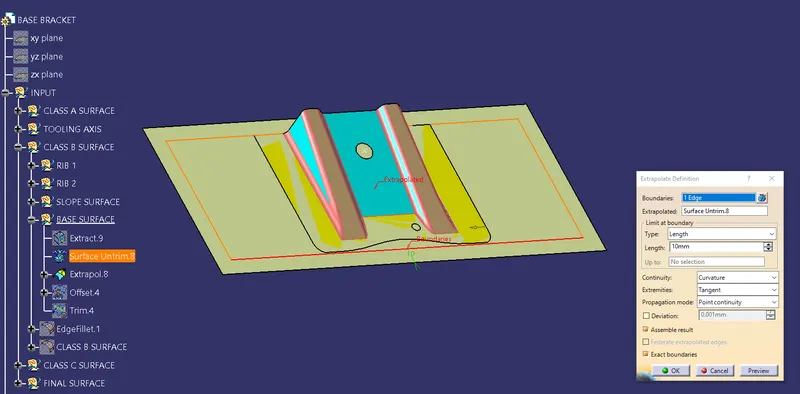
- Offset the trim surface at a distance of 2.5 mm.
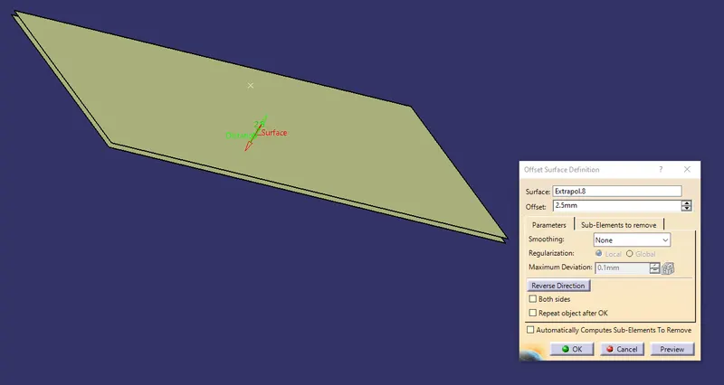
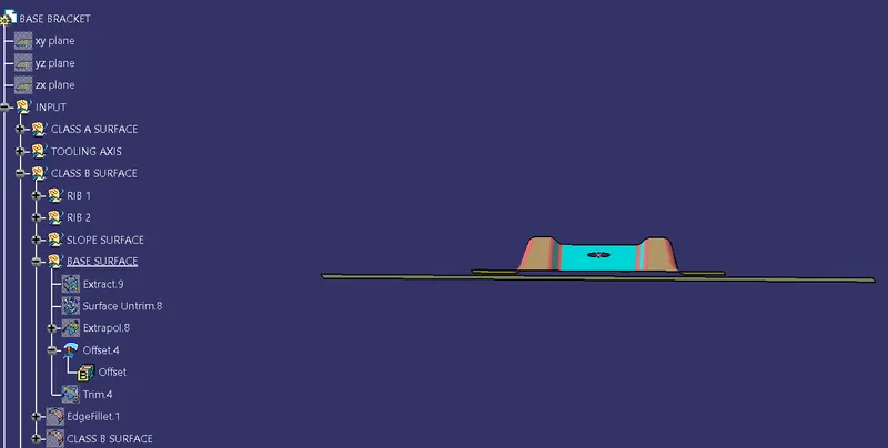
- The Bellow image shows the final trim of the slope surface and base surface.
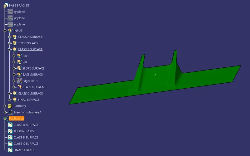
The Bellow image shows the final surface of the Class-B Surface.
3) Class-C surface
- Create boundary as point continuity
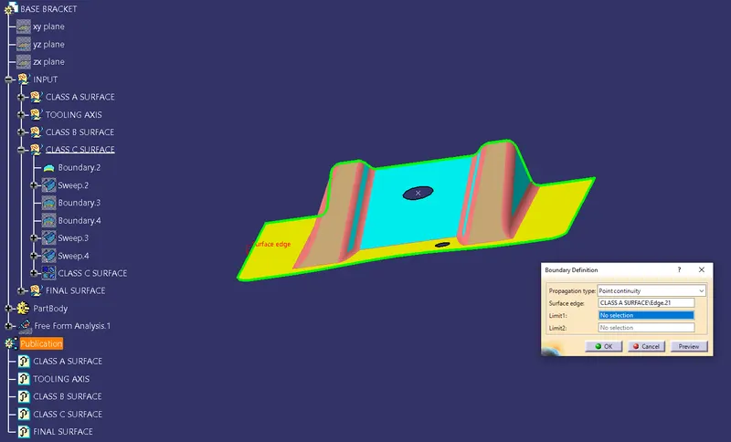
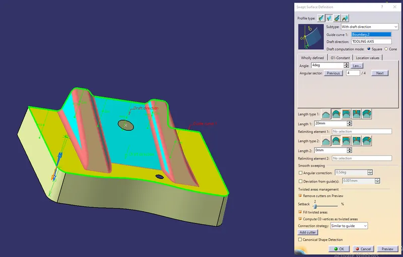
- Select sweep in line profile type select with draft direction. Select guide curve 1 as boundary and draft direction as tooling axis. The arrow should be selected correctly.
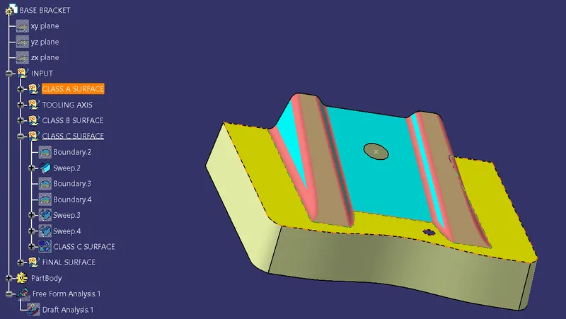
- Create boundary of both the hole and sweep them with draft direction.
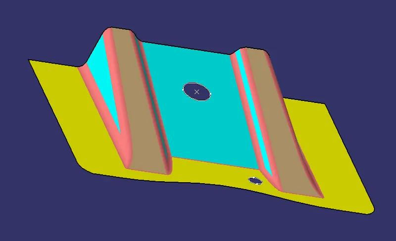
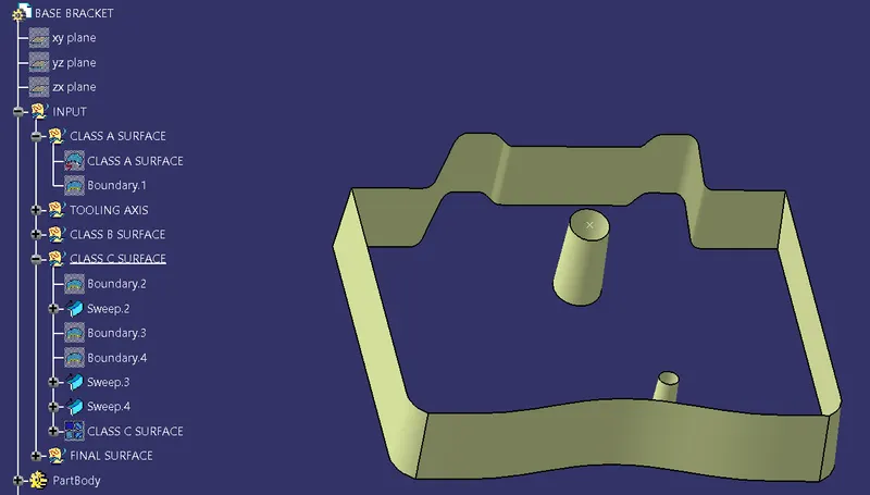
- Join the hole with the wall and then with the Class-A Surface.
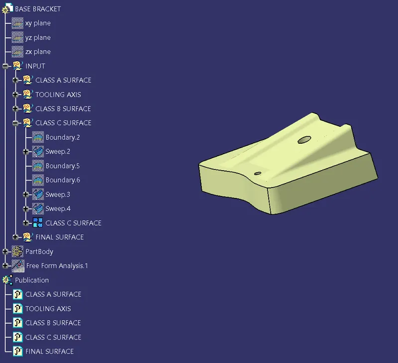
vi) FINAL SURFACE
Trim the Class-B surface with Class-C surface
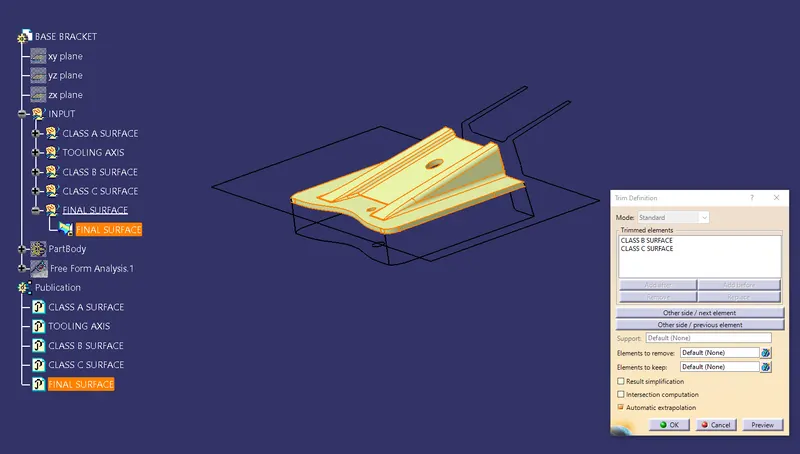
4)Publish all the Tooling Axis, Class-A, Class-B, Class-C, and Final surface
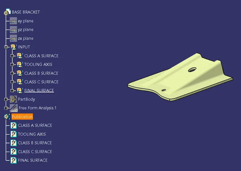
5)Create the close surface
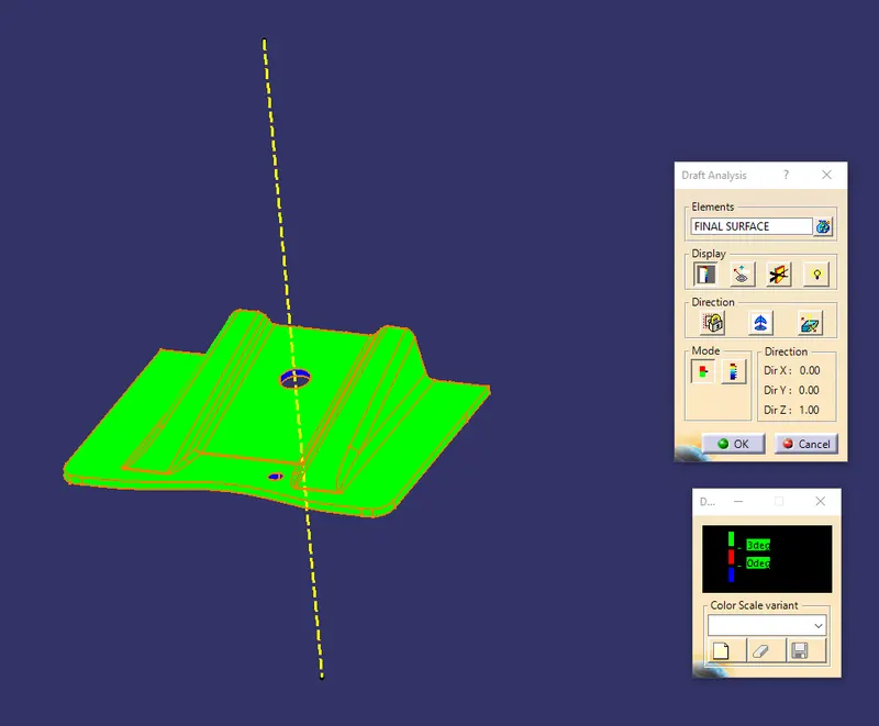
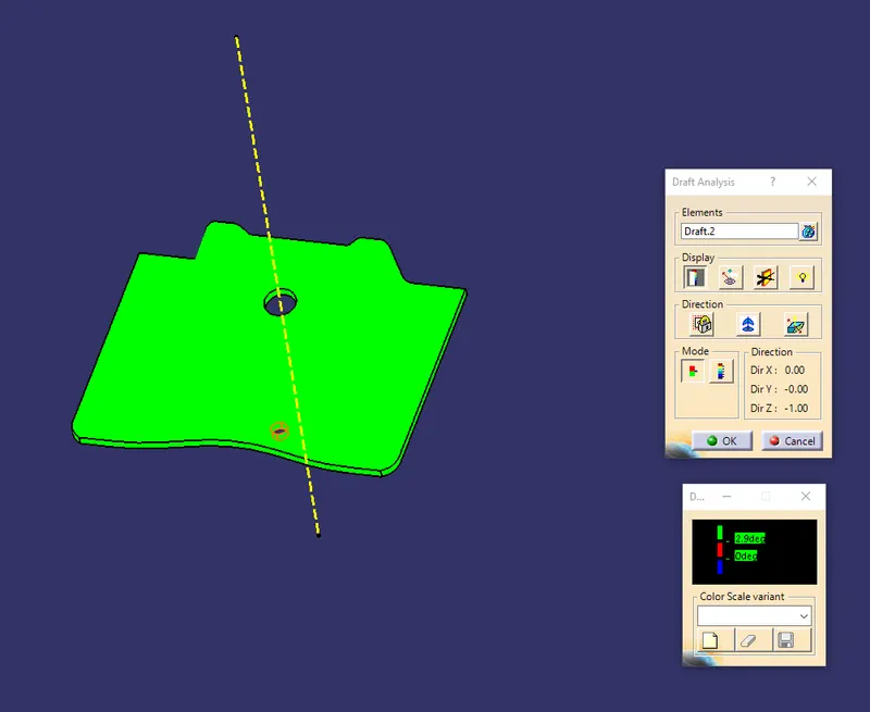
DRAFT ANALYSIS
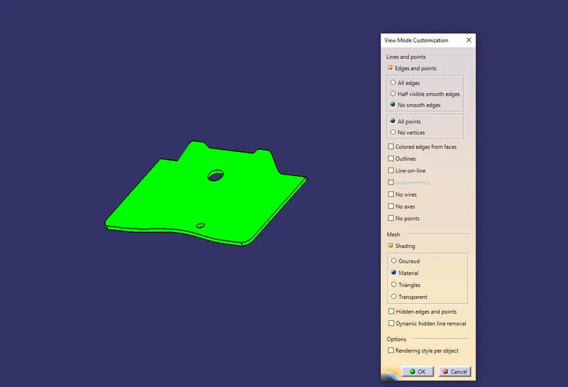
- To start the draft analysis first to material view mode customization and select material.
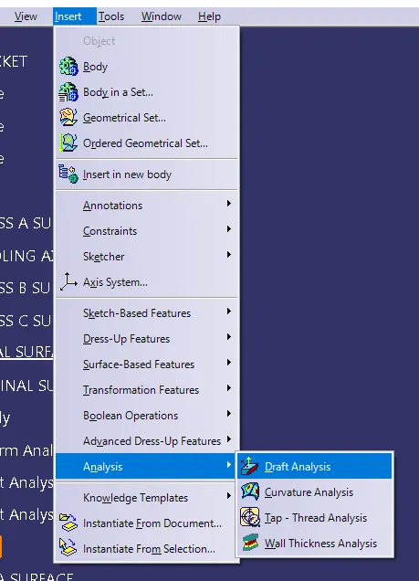
- Go to "Insert>Analysis>Draft analysis"
- Fix the compass in the tooling axis by dragging the compass to the tooling axis.
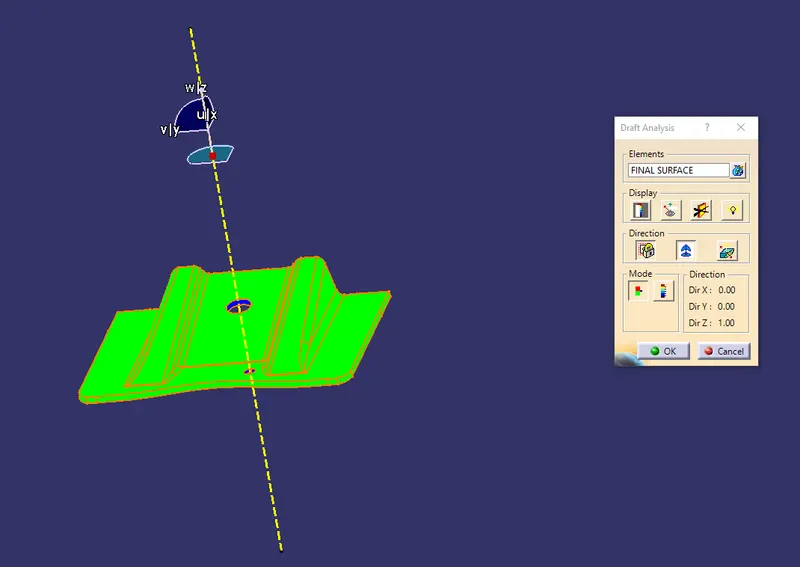
- Select a show or hide the color scale option under the display.
VARIOUS ORIENTATION(ISOMETRIC, FRONT, SIDE AND, TOP VIEW)
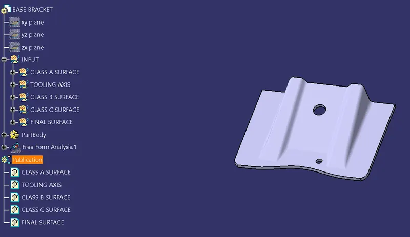
- Isometric view
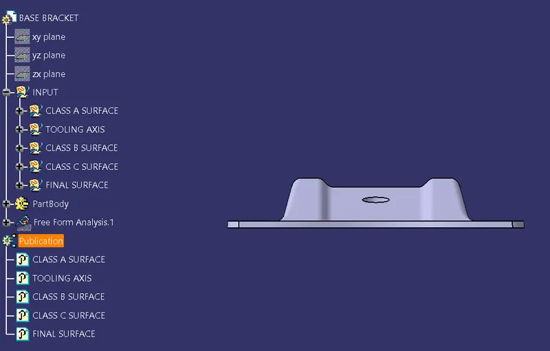
- Front view
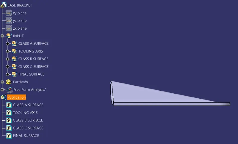
- Side view
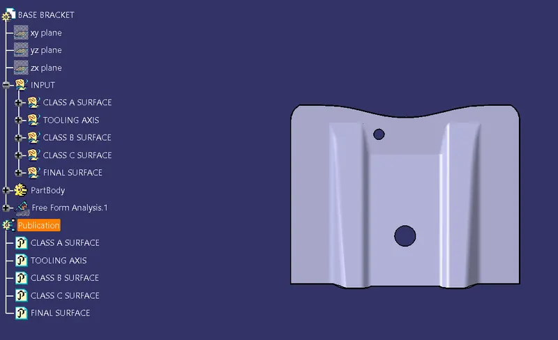
- Top view
- Multi-view
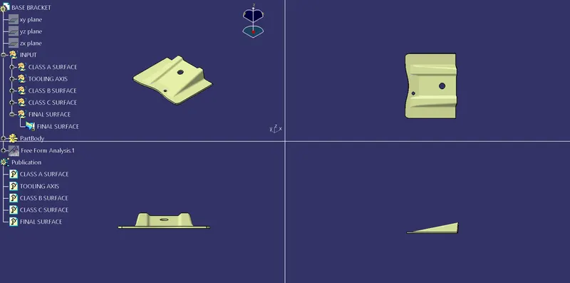
The base bracket component is created using Class-A surface and draft analysis has been performed.