Week 8 - Challenge 5 - Core & Cavity Design
AIM:- To create Core and cavity block of a switch bezel component.
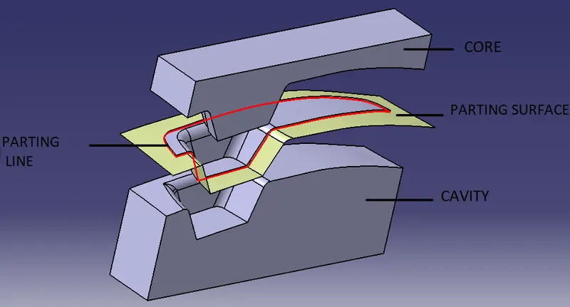
To create a plastic part there are two major components core and cavity. The core has the impression and the cavity have the depression.
Design rules:-
- The proper draft should be given to the part so that the part can be ejected from the core and cavity.
- Minimum 3 degree draft should be given to the Class C surface. If the part has 0 degree draft then there will be friction occurs in the core and cavity.
- The side core should be avoided because the manufacturing cost of the component increases.
- The parting line is the line that split the mold into two halves the core and the cavity. So the parting line should be always in the Class B surface so that we can not see the parting line.
- Avoid sharp corners as the cost to manufacture the sharp corner is very high.
- The thickness of the part should always have uniform thickness throughout the part.
PROCEDURE:-
Tooling Axis:-
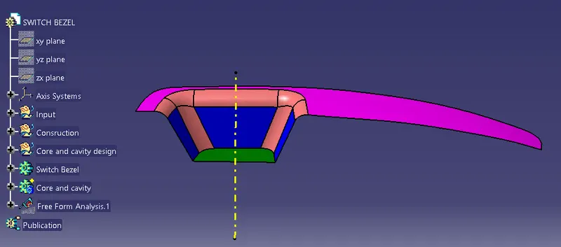
The tooling axis is the direction in which the core and cavity open or close. The design engineer analyzes the class A surface and finds the best possible tooling direction for manufacturing the part. Bellow image shows the tooling axis of the switch bezel.
Core:-
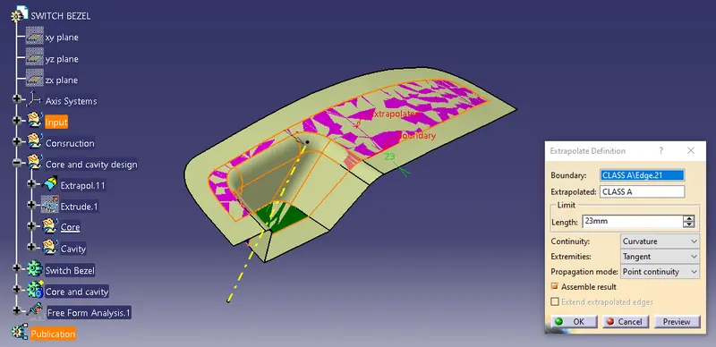
- Core design starts with extrapolating the class A surface.
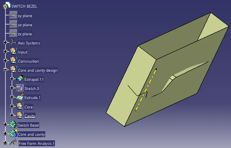
- Then Extrude the rectangle.
- The next step is to trim the extrapolate with the class c surface.
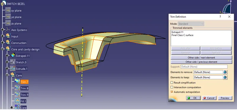
- Then trim the surface with the class B surface.
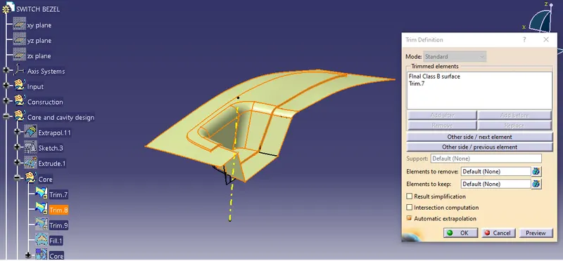
- Then trim the surface with the extrapolate.
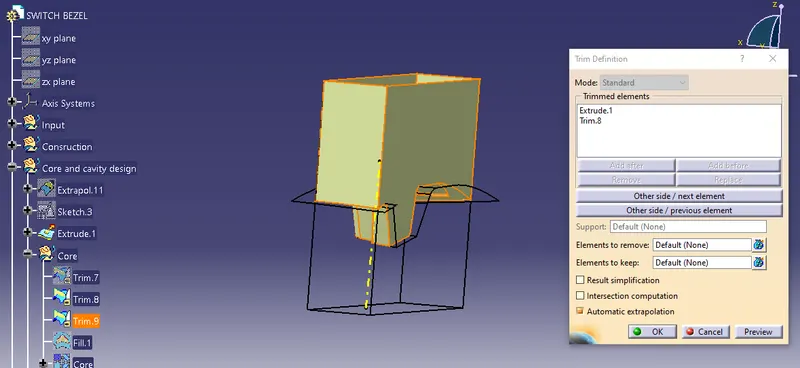
- Finally, fill and join the surface to create the core.
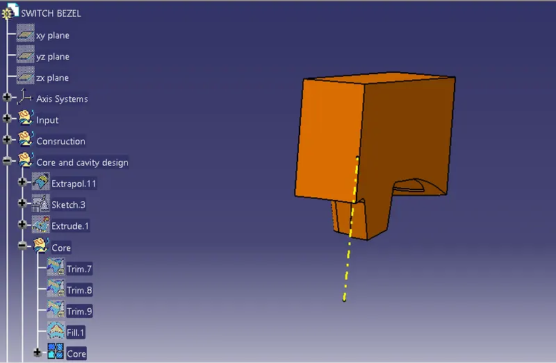
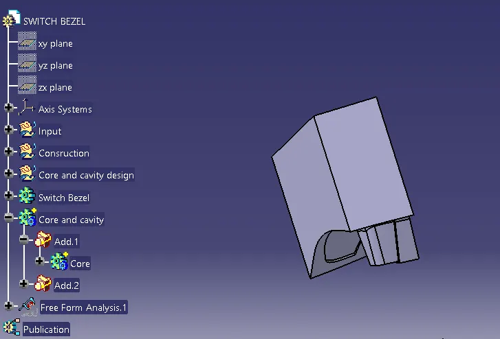
- Billow image shows the close surface of the core.
Cavity:-
- Do the same extrapolate the class A surface and extrude the rectangle.
- Then trim the extrapolate with Class B surface.
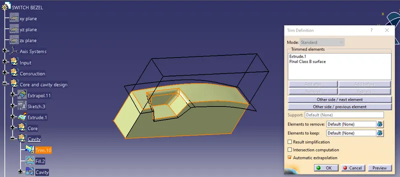
- Finally, fill and join the surface to create the cavity.
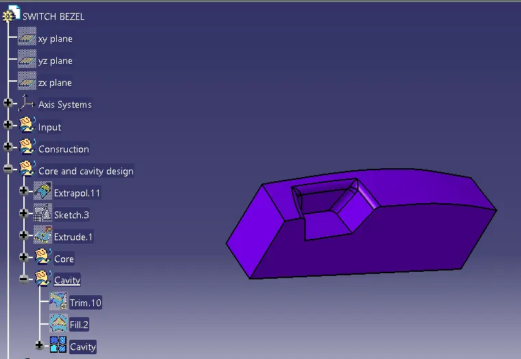
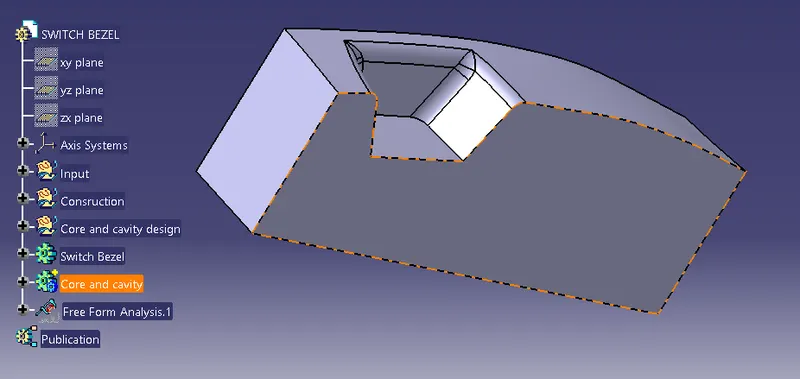
- Billow image shows the close surface of the cavity.
Parting line and parting surface:-
DRAFT ANALYSIS:-
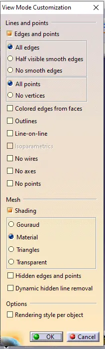
- To start the draft analysis first go to material view mode customization and select material.
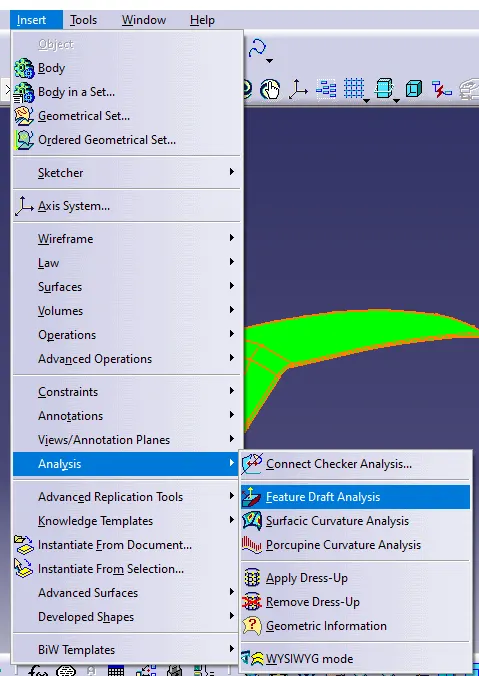
- Go to "Insert>Analysis>Draft analysis"
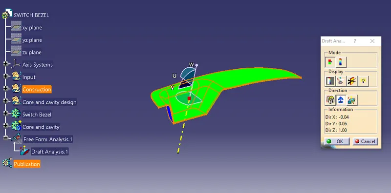
- Fix the compass in the tooling axis by dragging the compass to the tooling axis.
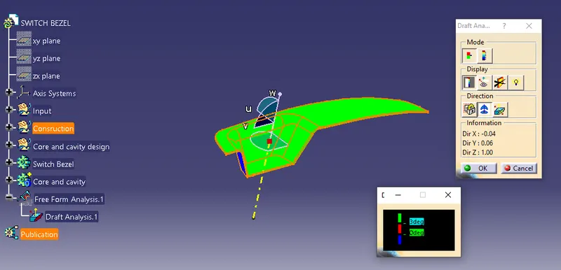
- Select a show or hide the color scale option under the display.
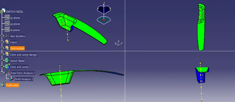
Various orientation(Isometric, Top, Front, Side view)
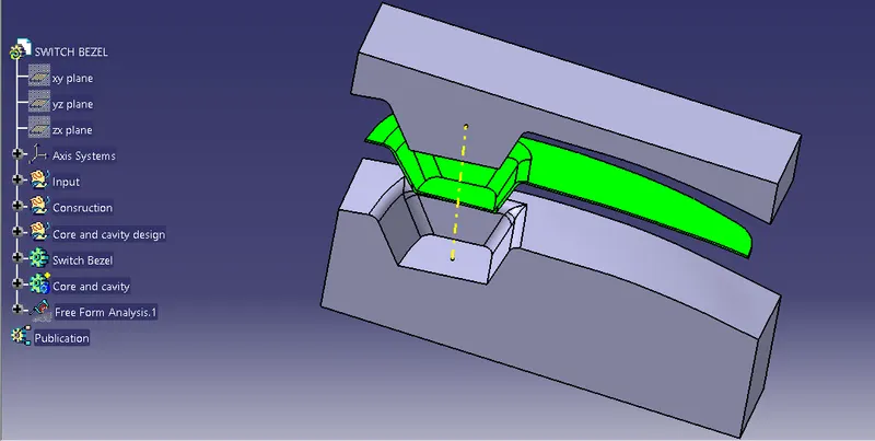
- Isometric view
- Top view
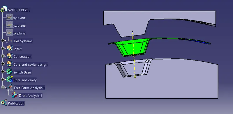
- Front view
- Side View
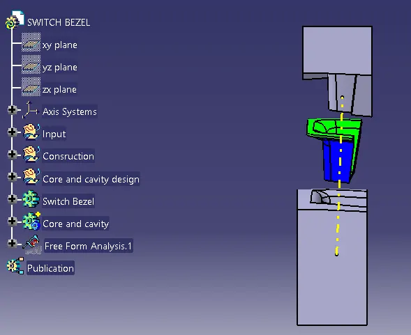
The core and cavity design of the switch bezel is made and the draft analysis of the switch bezel is also performed.