Week 1:- Introduction to BiW and Fixtures Challenge
For this week's challenge, provide an answer to the questions mentioned below. You can type in your answers in the space provided. Be as descriptive as possible and use appropriate images if required.
Each question will grant you 30 marks. The overall presentation of answers will grant you an additional 20 marks.
- What is BIW & define its parts?
- What do you understand by BIW nomenclature?
- What is fixture & its types?
- What is the basic principle of fixture design?
- Elaborate types of BIW Stations?
- What are the basic terminologies used in the BIW fixture?
1.What is BIW & define its parts?
Body in White (B.I.W) refers to the welded Sheetmetal components which form the welded Sheetmetal components which forms the structure of vehicles which will be engaged with the other components like Engine, chassis, Interior and exterior trims.
Body in white (BIW) refers to the stage in the automobile manufacturing in which a car body’s components have been joined together, using one or a combination of different techniques: welding (spot, MIG/MAG), riveting, clinching, bonding, laser brazing etc.
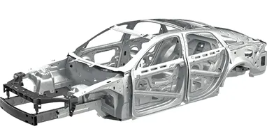
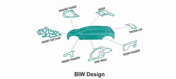
Body in White, or BIW, is a stage in the production of automobiles in which all sheet metal components such as the roof, body side, under body, backdoor, cross members, and other components are welded together and the resulting body is dipped in a primer solution, which has a greyish colour and thus gives the body its name. The car's shape is determined by the BIW, which is obtained after welding and before painting.
BODY SIDE consists of:
- Body side outer
- Body side inner
It generally refers to both the sides of the car that is left and right side. It mounts various BIW components like A-pillar, B-pillar, C-pillar, Panel side sill etc.
UNDER BODY consists of:
- Front end under frame: This is the compartment are where the engine and other components of automobile like battery, radiator etc mounts.
- Main floor: This is the compartment where the interior parts like seats; infotainment panel etc will be mounted.
- Rear end under frame: This compartment shapes the rear end of the car. This is what provides space of mounting of rear closure parts and boot space.
CLOSURE components consist of:
- Front door: Two front doors on each side.
- Rear door: Two rear doors on each side.
- Hood: To cover the engine compartment.
- Trunk lid: To cover the interior and boot space.
ROOF consists of:
- Roof inner.
- Roof outer
FENDER: The component seats between side body and front end under frame.
The below image shows precisely what a BIW of monocoque consists of
2.What do you understand by BIW nomenclature?
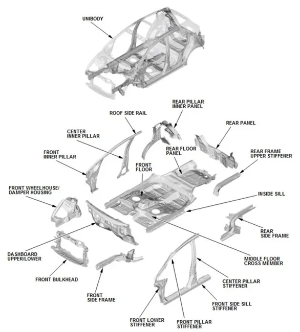
A nomenclature in BIW is basically naming every part of the body. These names can be said as subparts of the already categorized parts above. The nomenclature differs a little bit from region to region but the overall idea is to name individual automotive sheet metal components. Below images show the nomenclature of BIW:
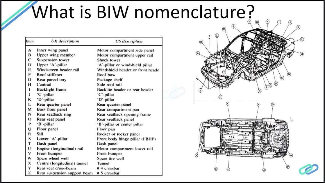
As automotive industries spread worldwide, the terms and standards will be different for similar components.
· The terms are standard but they differ in some countries.
· As automotive industries spread worldwide, the terms and standards will be different for similar components.
· For example, one component of BIW is known as inner wing panel in the European description and the same component of BIW is known as the Motor compartment side panel in the US description.
3.What is fixture & its types?
Fixture is a device which holds work piece to be processed by using 3-2-1 principle. In general, a welding fixture(tool) consist of number of units together to hold the car panel & is mounted on a base unit.
Welding fixtures are normally designed to hold & support the various work pieces to be welded. It is necessary to support them in a proper location which is capable of preventing distortion in work pieces during welding. Due to this the locating elements need to be placed carefully, clamping elements has to be done light but firm, Place of clamping elements has to be clear of the welding area & the fixture has to be quite stable & rigid to withstand the welding stresses.
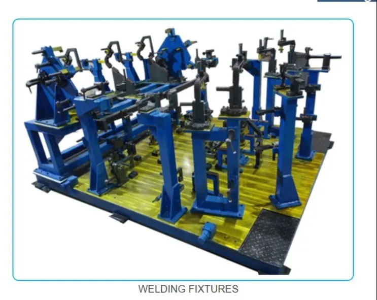
There are few types of fixtures according to that purpose those following as follows:
In general, these classified 3 types: 1. Production fixture, 2. Pre-production operation fixture, 3. Checking fixture
Production Fixtures are work-holding devices and locating elements that locate, hold, and support the workpiece in a fixed, proper position during the machining process with respect to the machining tools. The most common type of fixture is the Vise jaw found in nearly all workshops. Their main advantages are:
· Increased productivity
· Increased machining accuracy
· High-speed manufacturing process
· Maintained interchangeability
· High clamping rigidity for CNC and turning operations on large parts
· The increased quality level of the finished product
These fixtures are used for mass production. Since these fixtures are used for mass production, they should be simple, rigid and hard. These fixtures should be periodically maintained in regular intervals to avoid errors and repairs. The design of the fixture should be in such a way that it should be easy to load and unload the workpiece within seconds to increase the productivity of the processing/assembly.
Pre-production operation fixtures are basically newly designed fixtures for the new products or parts. These may be complex, manual and heavy based on the application. These can be referred as the protype fixtures. Once the preproduction operation fixture functions properly, then modifications are made to improve and to make it simple and reliable. These fixtures are used in special cases or during initial or trail stages of processing/production. These fixtures are commonly used during the prototype stage to test the productivity and feasibility of the fixture. They require a lot of study and detailing because they are used in the pre-production stage. If a new standard or process is required, the pre-production fixture is modified to become the production fixture used on the assembly line.
4.What is the basic principle of fixture design?
The major portion of fixture design is holding the workpiece firmly. The main principle of the fixture design is 3-2-1 principle. All the Degrees of Freedom of the workpiece are to be constraint.
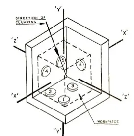
For any free body there are total 12 degrees of freedom as follows:
6 translational degrees of freedom: +x, +y, +z, -x, -y, -z &
6 rotational degrees of freedom:
Clockwise around X-axis (CROT-X), Anti Clockwise around x-axis (ACROT-X)
Clockwise around Y-axis (CROT-Y), Anti Clockwise around Y-axis (ACROT-Y)
Clockwise around Z-axis (CROT-Z), Anti Clockwise around Z-axis (ACROT-Z)
When designing the fixture always all 12 degrees of freedom of workpiece should fix.
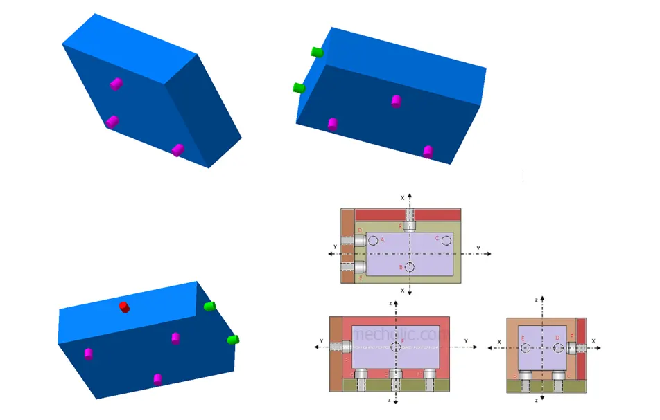
First the workpiece is constraint by 3 pins on below surface. This lock the Y DOF, clockwise around X axis (CROT-X); Anticlockwise around X axis (ACROT-X) the Clockwise around Z axis (CROT-Z); Anticlockwise around Z axis (ACROT-Z).
Then another side perpendicular to the below surface is constraint by 2 pins. This locks -Z and +ZDOF and Clockwise around Y axis (CROT-Y); Anticlockwise around Y axis (ACROT-Y).
Then any one side perpendicular to both the below and the other 2 side of the workpiece is constraint by 1 pin. This locks X DOF.
5.Elaborate types of BIW Stations?
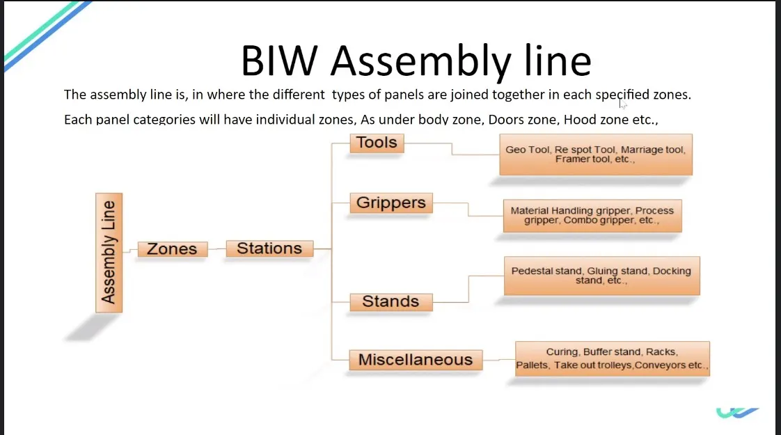
The BIW assembly line is where different types of panels are joined together in each specified zone like Underbody zone, Hood zone Etc.
These zones are further subdivided into stations, where various processes like welding gluing and inspection are done to the part of that particular zone before they are being assembled together. For instance, in the roof zone, various reinforcement is to be added before they are married to the side zone.
The BIW assembly line can be classified as follows:
1. Tools
2. Grippers
3. Stands
4. Miscellaneous
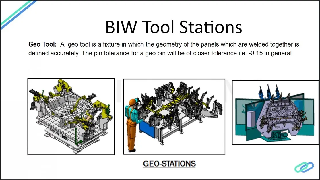
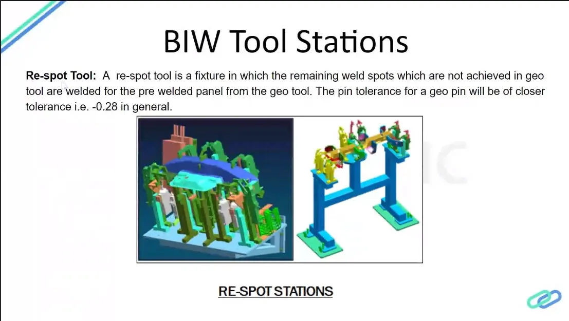
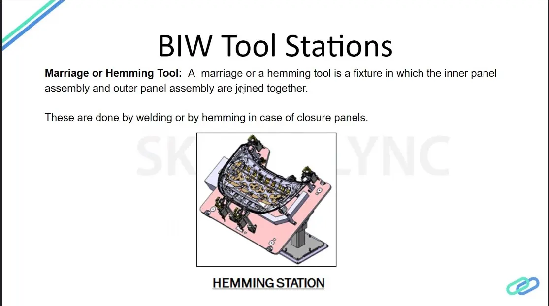
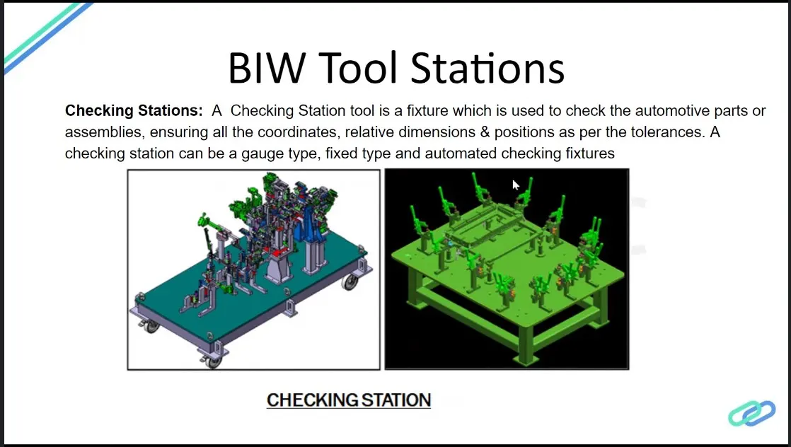
A tool is a fixture which consists of number of different units together to hold a car part in general.
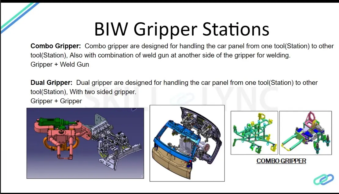
Dual Gripper: These are two-sided where we want one LH & one RH part, these grippers are used. It can handle the material from one station to another station. Ex: Gripper + Gripper
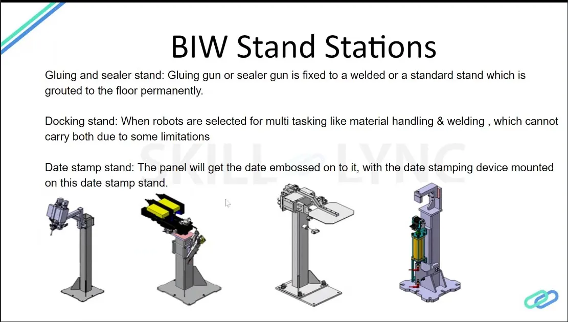
Miscellaneous stand
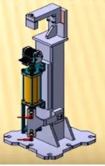
Curing:
After gluing it needs some time to cool down, so we put the assembly on some belts & it will take the panel to another station & meanwhile gluing will cool down.
Buffer stand:
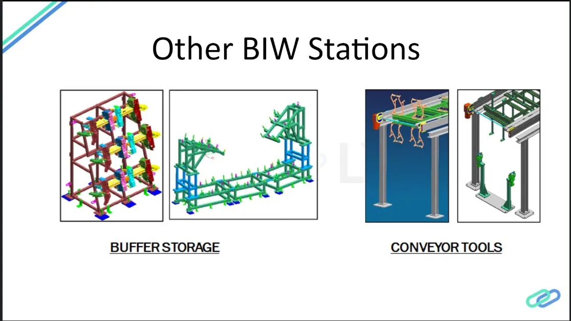
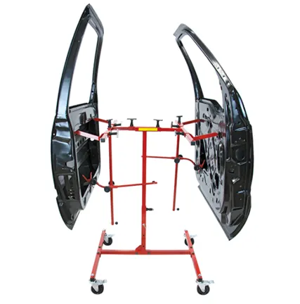
After some operation, we can put the no. of assemblies in this stand which is buffer stock & it can be transported to another station in easy They are also used to store the inventory while the machine is undergoing some maintenance.
Take out trolleys:
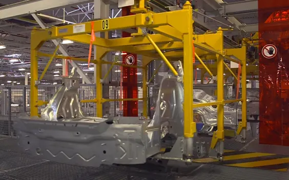
It used to take out some panels for inspection to rectify the process is going in the right or not between the cycle.
Conveyer:
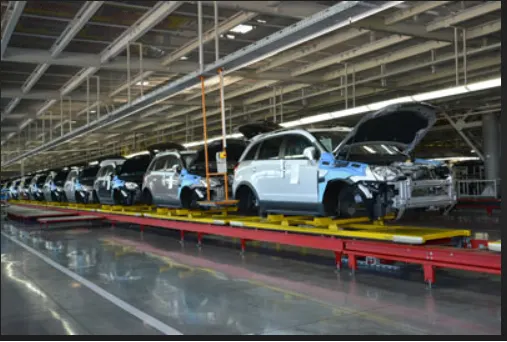
The conveyer is the rotating path that transports the parts to the next station which are kept over it.
6.What are the basic terminologies used in the BIW fixture?
Basic terminologies used in the BIW fixture:
The following terminologies are used in BIW
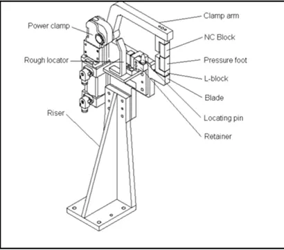
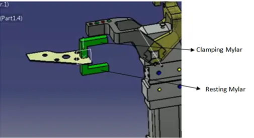
NC/Mylars/Fingers/Back-ups:
Mylars are the component that holds the panel while These are placed from topside & from the bottom side also. The top side Mylars called Clamping Mylars & the bottom side Mylars called Resting Mylars. Every clamping Mylars have resting Mylars. It doesn't allow deformation of the part due to welding stresses.
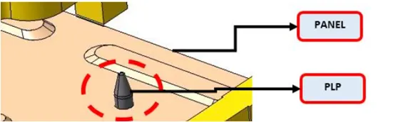
Principle locating point (PLP)
These are the points that are used for the accurate location of the part to maintain the geometry of the part. There is lots of holes on the panel which are not accurate due to stamping operation. The PLP are defined in the drawing. The positional dimensions or relative dimensions are very precise in stamping & in fixtures also.
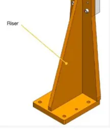
Risers
Risers are of different types like L-typer rises, square tube riser is the manufacturing part which gives height to the assemblies.
Blade
Blades are plates mounted on the other parts like cylinder, arms, etc are mounted on the blade.
Shims
Shims are the small part that comes with the thickness of 0.1mm, 0.2mm, 0.5mm, etc. These will compensate for the stackup tolerance which reflects at the panel holding part called We give tolerance to all the parts of the fixture. Due to this tolerance, the Mylars will either lift up or goes down from their defined position.
If the Mylars go down from the defined height it will make an impression or dent on the panel.
If the Mylars lift up then there will be a distortion due to welding stress. To adjust the Mylars At its defined position we use shims so the panel won't be deformed & also don't get any impression on it.
Rough locators
The operator can place the part in the wrong orientation The rough locator will work as a guide while placing the part in the fixture & the part will be loaded in the desired orientation. It is a part of fool proofing.
Hardware
Hardware is like the Hex head bolts, Allen Bolts, Hex nuts, Spring washers, Self-locking nuts
CMM
CMM stands for coordinate measuring machine. It is a device that measures the geometry of physical objects by sensing discrete points on the surface of the object with a probe. It generates a report by comparing the data with the CAD file data.
Unit
The fixture is the assembly of different types of units to form a part. There are different units like pin unit, base unit, clamping unit, etc.
Number plates
The number plate is the aluminium embossed plate placed on each unit for easily recognizing the part unit.
Nameplate
The data like manufacturing company name, fixture type, Fixture weight is embossed on the plate & joined to the fixture.
Clamp Arm
The clamp arm is the part of the clamp unit which moves an Over clamp arm the Mylars are mounted.
Pivot
It is an axis about which the clamp arm will rotate
Class A Surface/Skin surface
The outer panels of the car like a hood, door, backdoor, fender, roof are visible to the customer. The outer panels should be aesthetically very good. No scratches or dent is acceptable over it.
While designing the fixture to the skin surface the clamping material should be soft, so that it could not able to left any impression or dent over the skin. generally, nylon or PU material is used for clamping purposes.
Reed switches & sensors
These are the electric components used in automated The reed switch is an electrical switch operated by an applied magnetic field. The detects the panel is loaded or not is done by sensors.