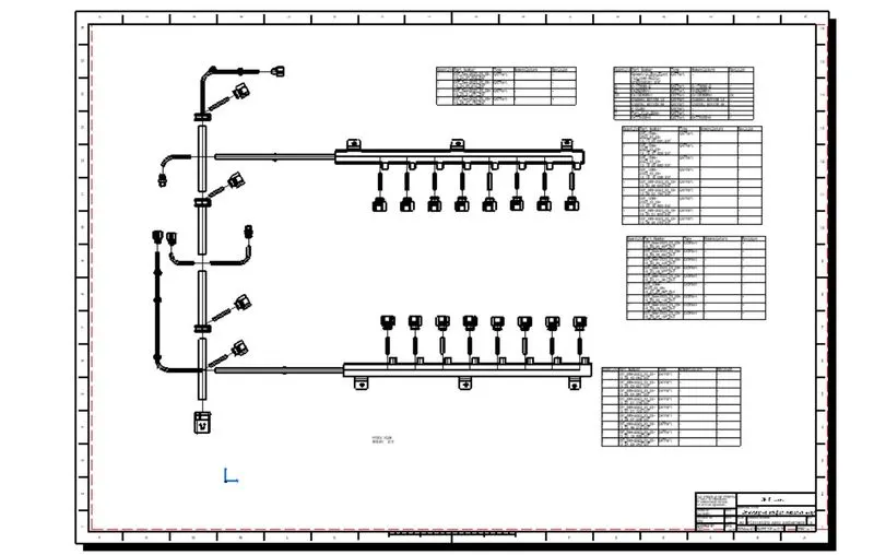
Wiring harness on Given Engine and Prepare flatten view drawing in CATIA V5
Statement of assignment:
Route the Wiring harness on Given Engine and Prepare flatten view drawing in CATIA V5. Application of all Packaging rules, Industry best practices studied in this course shall be demonstrated in design. Apply Protection coverings as required.
Available connector 3D data can be used, or you can download the connectors from www.te.com
Prepare & submit all necessary reports like clearance, Clipping/Clamping selection, Harness fixing requirements, Harness continuity, Assumptions if any along with CATIA 3D data.
Engine cad data to be downloaded from www.grabcad.com
Engine file
CAD Files
Objective:
Route the Wiring harness on Given Engine and Prepare flatten view drawing on CATIA V5. Application of all Packaging rules, Industry best practices studied in the course shall be demonstrated in design. Apply Protection coverings as required.
Prepare and submit all necessary reports like clearance, Clipping/Clamping selection, Harness fixing requirements, Harness continuity.
Rules or Assumption to be followed while Routing the Wiring Harness.
- Wiring harness should be routed in such way that it is easy to assemble and access.
- Easy manufacturing, installation, removal and maintenance have to be considered while designing the wire harness.
- Wiring Harness should be kept away from sharp environment like edges, corners etc.
- Avoid harness routing and clipping in the blind zones or hard to reach areas during harness assembly or service.
- Provide additional slack if needed according to the surrounding and harness bending requirement. If harness is passing through the closures/doors or tail gates then envelope dimensions during opening and closing of doors shall be considered to provide the slack. Check the harness slack requirements with open and close conditions to avoid excess slack.
- Routing through small structural holes and openings shall be avoided. To minimize chaffing and handling of the wiring harness during installation.
- It should be make sure that there is no case of fouling while designing the wiring harness in the CAD environment. Additional mounting equipments like clips/clamps may be used to avoid fouling.
- Use of rubber grommet is recommended if harness is passing through sheet metal panels. Example- firewall, passing to door, tail gate etc.
- The branch length should be greater than
- The minimum distance between the clip and branch point should be at least 25mm.
- The minimum distance between the two branch points should be at least 50mm.
- Clips/clamps used for the wiring harness should be easily available in the market to avoid extra cost for custom mounting solutions.
Considering above conditions keep in mind first need to download the required components from te.com and have to defined as electrical components.
In the process of defining as electrical product need to follow the following steps for all components
1.First step have to provide reference elements like point, axis system, plane at part design workbench
2.after providing the reference elements need to shift to electrical part design work bench to provide electrical properties.
- At electrical part design work bench first need to define what kind of component that is like connector, support, back shell, mounting equipment, contact, shell, filler plug, protection part using Electrical device define tool bar.
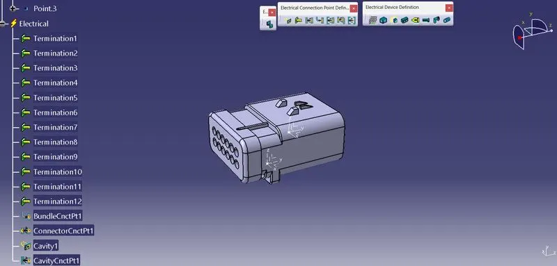
4.After above step need to provide Electrical connection point definition which are like terminals, bundle connection point, connector connection point, cavity connection point, back shell connection point etc.
Components used in the assembly:(connectors, shells, clips, clamps, Channels)
12pole Inter connection connector
Cavity clip
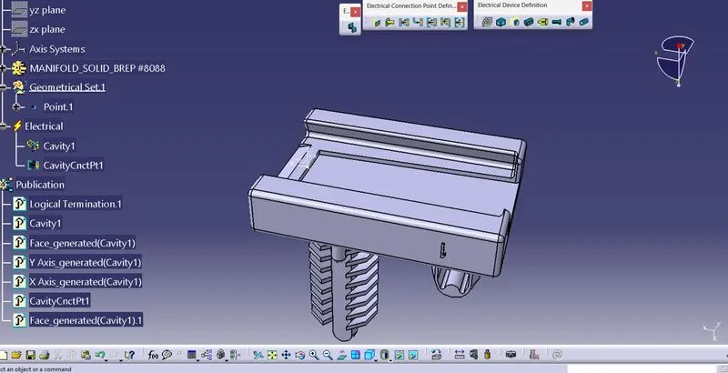
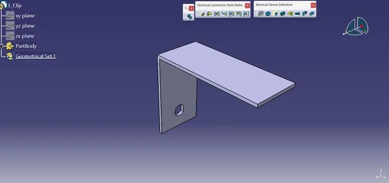
Mechanical equipment for support of 12pole connector
Connector & Bundle connection connector (Ignition and other)-20Nos used
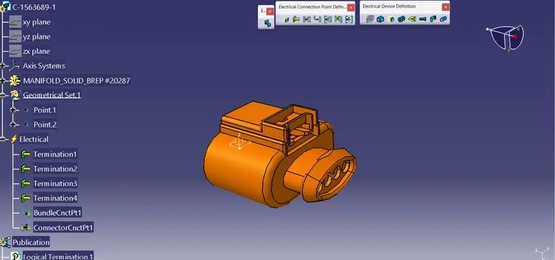
Guiding channel bottom LH& RH
Guiding channel top LH&RH as mechanical equipment (protection)
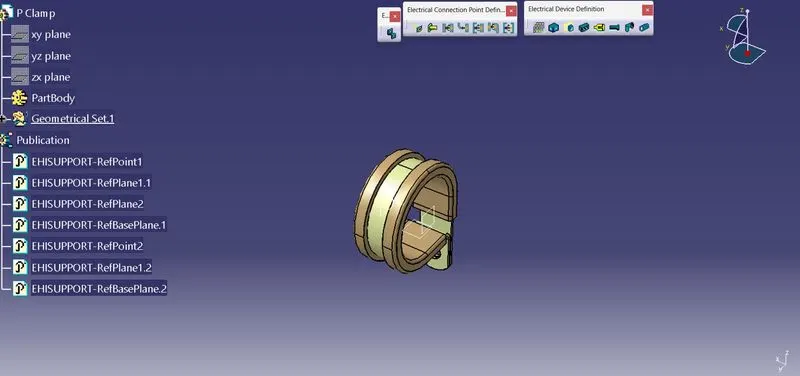
P-clamp as support equipment to hold the bundle
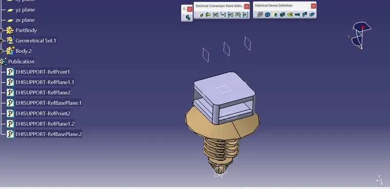
Furr tree clip as support equipment to suppoert the bundle
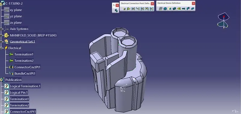
Other connecter used for sensing thermal, speed etc
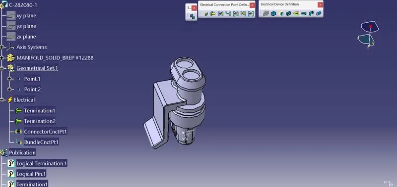
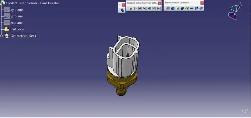
Collent sensor placed at engine as Mechanical component.
WIRING HARNESS ROUTING:
After importing the electrical components into the assembly work bench all components need to place respective positions to make smooth harness. After the completion of positioning into one product that product need to define as geometric bundle at Electrical harness assembly. After defining geometrical bundle properties need to go to the multi – branchable document option in CREATION tool bar at same workbench to route harness branch definition.
In this assembly I have used 15mm is main branch diameter subbranch diameter as 10mm and connector connection branches are as 5mm diameter.
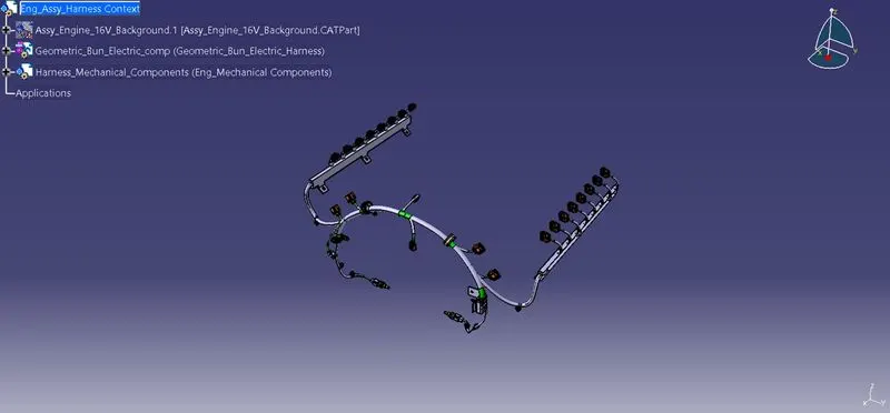
After completion of total harness, the assembly as follows:
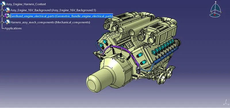
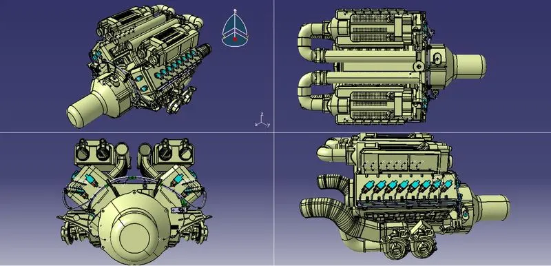
The only bundle harness looks as follows: (Engine surface file is hidden)
FLATTENING:
After completion of harness routing need to create new product file to create the flattening.
After creating the product file need to shift to the Electrical Harness Flattenning workbench.
Now need to provide flattening parameters, for the product.
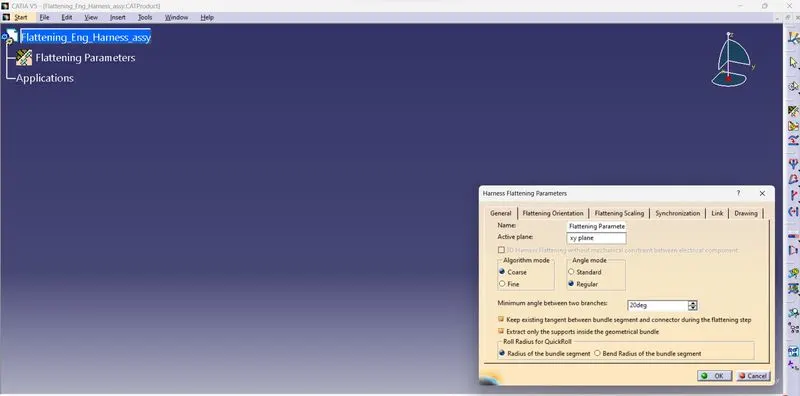
After creation of parameters need to extract the geometric bundle harness to the flattening work bench.
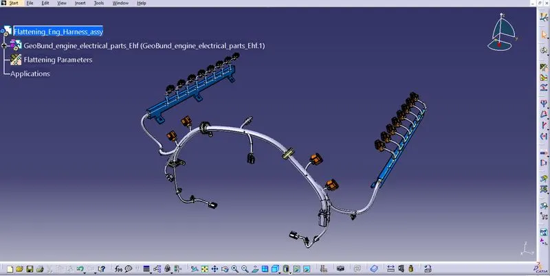
Flttening the imported harness assembly using flattening tool.
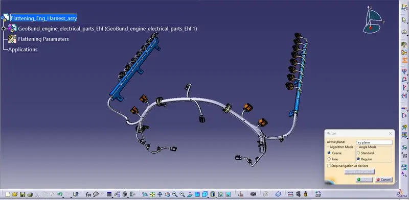
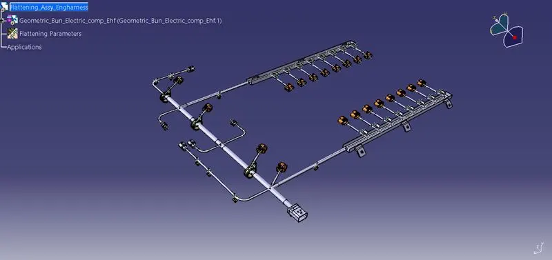
After flattening of the final flattening looks as follows:
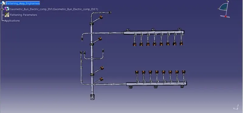
Top view of the above final flattening assembly
Drawing of Flatten harness assembly :
In this first create the drawing file and save the document and import the flatten assembly to the sheet. Go to Insert à Generationà Automatic Bill of Material and select on the sheet Billa of material table will appear.