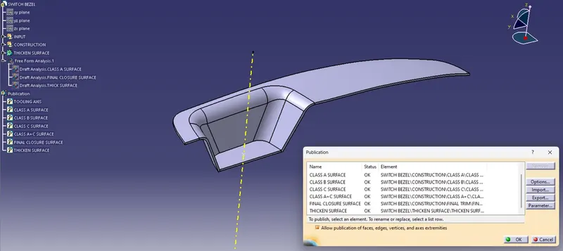
Week 9 - Challenge 2 - Switch Bezel Design
AIM: creating the Switch Bezel using given class A surface.
CLASS A: The top (which is given) surface of the component is called as class A surface.
CLASS B: The bottom surface of the component is called as class B surface.
CLASS C: The surface which is connecting CLASS A & CLASS B surfaces is called as class c surface.
First, we need to check the given surface quality that is class A surface. Using boundary condition of operation tool bar check the continuity than have to check draft analysis.
Draft analysis: The draft analysis technique is used to analyse whether our part model created in CAD is manufacturable based on the draft condition applied. Here the part should get easily removed from the panel dies or Mold (in case of plastic and sheet metal parts).
No parts can be ejected from the tool if it is having a straight 90-degree profile from its base surface. A small draft angle is provided to each and every area of the component in order to get easy removal of the component from the tool.
Here we are providing a direction in which components should eject in order to get easy removal of components from the tool. In other words, it also lets us know whether the model is having a draft angle and how much is the draft angle from the tool direction.
To do draft analysis in CAD first, we need to create the tooling axis. The tooling axis created by three methods
- Compass Method 2.Bisecting method 3. Normal to surface method
In this challenge me used normal to surface method.
Normal To Surface method:
In this method extract one flat surface from the class A surface and create one point on the extracted surface. Create the dummy axis for tooling direction.
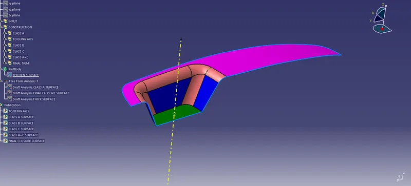
After creating of dummy axis, The Drafting analysis was performed using the Feature Draft Analysis command.
Using this command, the compass was set on the main tooling axis and the Draft angle was changed to 3 degrees.
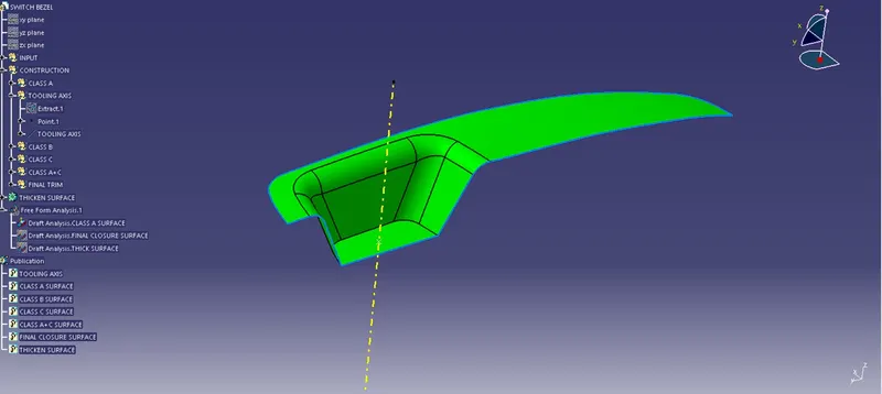
Creating Class B Surface:
- The required surfaces were obtained from the Class A surface using Extract
- These surfaces were further expanded using Untrim and Extrapolate
- The protruding surfaces were trimmed using the Trim command and a proper continuous surface was obtained.
- The same procedure was followed for the other side as well.
- These surfaces were offset according to the required thickness of the component.
- Normally the component thickness 3 or 2.5mm. But as per given data thickness of the component is 2.5mm. Fillets are done according to the class A & thickness of component.
- The final class B as follows below.
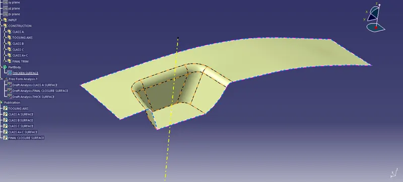
Creating Class C Surface
- The Class C surface connects the Class A and Class B surface.
- Initially the outline of the Class A surface was obtained using the Boundary
- The Sweep command was used along with draft direction, with a draft angle of 3 degree.
The final Class C surface looks as follows:
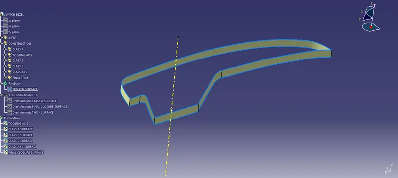
after creation of Class C, we need to join A&C. Finally, all the 3 surfaces were trimmed to form a closed surface.
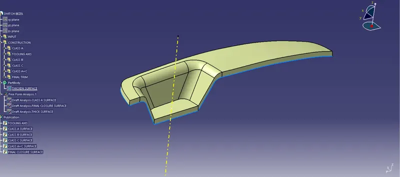
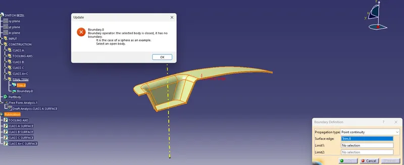
After completion of above steps, we need to check the boundary connection of closed surface than shift to the PART Work bench add the thickness using closure surface.
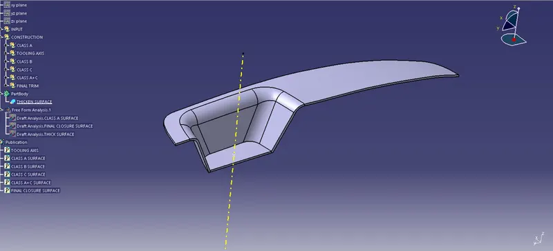
After this we need to check the draft analysis using the same tool axis. The thicken surface is cleared for 2.85degrees because of Class A profile.
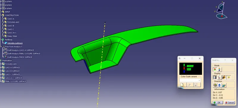
At each step Publications added to the component.