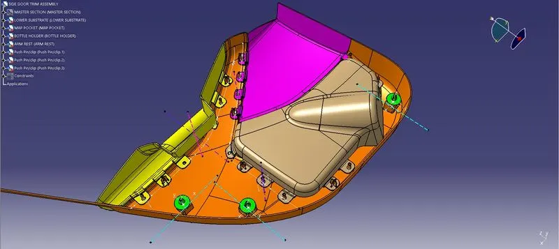
Week 12- Final project
AIM: Creating the side door trim assembly with engineering features from given Class A surfaces & Master sections.
Summary:
Assembly is done in 2 forms.
1.Top-Down Approach 2. Bottom-Up Approach
Top-Down approach is a method of creating and designing the parts in the assembly by taking the concern part as reference.
Bottom-Up approach is traditional approach where all the components are created outside assembly and assembled at assembly.
In this project we approach 2 types of approach. The engineering features are created by Top-down approach. Creating Class B, Class C surfaces, Assembling the Push pin and other external parts created by Bottom-Up approach.
While creating the ClassB and ClassC surface and engineering features the following steps need to follow:
1.conversion of STP or IGS file to product file. Create as Individual part and save each part using save management.
2.Tooling axis creation. Tooling axis is the direction in which the mould blocks move. While creating the tooling axis the main concern is that the tooling axis of all parts and plastic features need to be in same direction.
3.Preparation of ClassB & ClassC surface. Bottom-Up approach is used to create ClassB & ClassC surfaces.
4.Closed Surface creation. While creating the closed surface the intersection between the class A+C and Extrapolated Class B surface need to intersect completely each other.
5.B-side feature creation. After the closed surface the engineering features are created using Top-Down assembly approach. While creating the Dog-House should maintain the free space of 80-95mm Infront of dog-house to the lifter movement.
While creating engineering features maximum places the gap between each feature minimum 50mm.
Draft Angel: the degree of taper of the side wall of the mold or the angle of clearance designed to aid removal of a part from a mold. Plastic products have a draft angel from the ejection direction, but the height is below 4mm (such as a flat) and have special requirements except (but when the sidewall is not a large and no die when the need to do bit). The draft angel is usually 1-5 degrees, often take about 2 degrees, depending on the specific size, height, shape, to be able to successfully mould opening and does not affect the use of the principle of function. The front mold is usually 0.5 degree greater than the back cavity mold so that the product can remain in the back cavity. Usually pillow, insert, touch and other places are required to do with draft angel.
Engineering features:
1.Ribs: These are used for strengthen to the component. Design considerations for rib is thickness, draft, rib root thickness, height, spacing. Ribs are created on classB surface which is not visible outside.
2. Screw bosses: these features are used for attachment and assembly of components by self-tapping screw. Design considerations are tapping screw diameter and height.
3.Heat staking: These are used to join the two or more components permanently. Design considerations are material, cross section, height.
4.Dog house : These are supporting features and are used in plastic components. These used for maintain the proper gap between mating components and these are also contains bosses, locators to increase the strength.
5. Locators: These engineering features are used for arrest the degrees of freedom between the mating components. These are 2 types. 1. 2-way locator, 2.4-way locator. For a component there need to be minimum 2 locators are required.
In given project there are 4 Plastic parts are there.
1.Lower Substrate 2. Bottle holder 3. Map Pocket 4. Door armrest.
This assembly Lower substrate holds the other 3parts by locators, heat stakes and screw bosses. The three parts contains flanges to hold the lower substrate. The lower substrate also contains Dog-House which are used to support or fix the lower substrate to BIW or other components.
Tooling axis creation:
To create the tooling axis given master section is considered as reference in which the heat stake cross section. Actually, the outer walls of heat stake draft analysis is done through the main tooling axis. So, me used the outer walls of cross section (master section) and created the tooling axis using bisecting method.
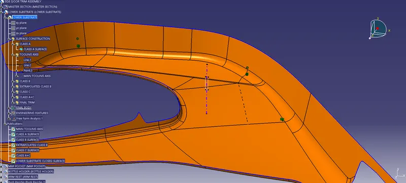
After creation of tooling axis inspection of classA surface and draft analysis is done with main tooling axis.
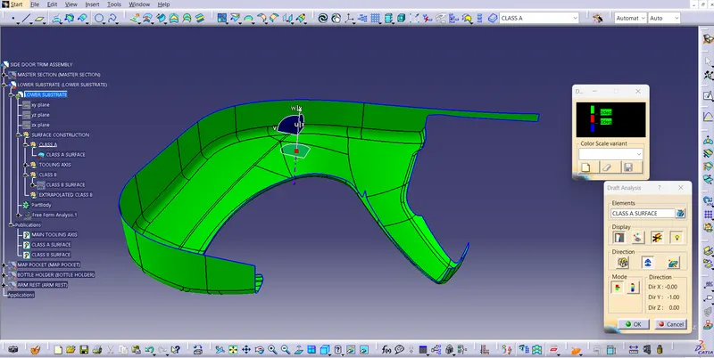
Creating Class B Surface:
To create class B offset the class A surface of 2.5mm inside as per the given master section. After offsetting the class B created as follows and the thickness of 2.5mm is considered from the given master section.
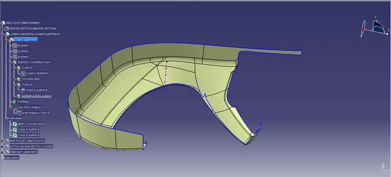
Creation of classC surface:
There is two types of class C surfaces are there one is parallel to the draft axis and another is perpendicular to the draft (tooling) axis. The following edges are parallel to the tooling axis and the picture as follows:
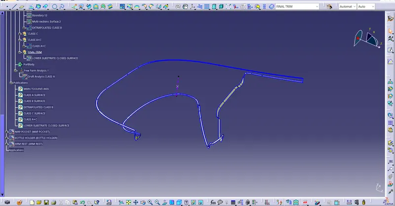
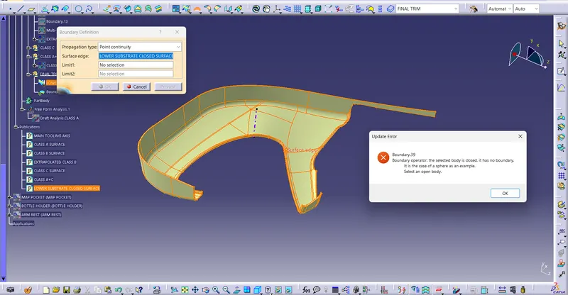
After creation of Class C, we need to join A&C. Finally, all the 3 surfaces were trimmed to form a closed surface. (A, B, C Surfaces). The final trim to form close surface. After creation of closure surface inspection is done through the boundary definition.
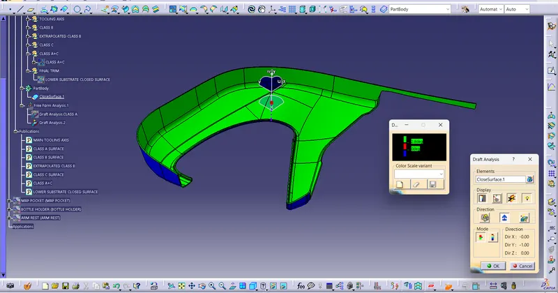
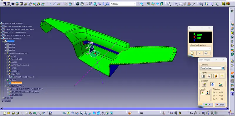
Now we shift to the part work bench to add the thickness to the model and after that draft analysis is done through main tooling axis. The solid body is cleared fully for 2.8degree angle and as follows:
Adding Engineering features from master section:
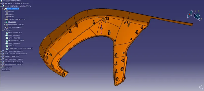
After adding thickness to the engineering features are created by using master section and also added some more features to assemble with components. The final picture of lower substrate as follows:
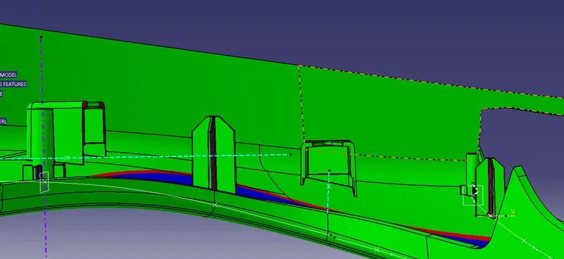
After creation of engineering features the draft analysis as follows with main tooling axis and side core axis:
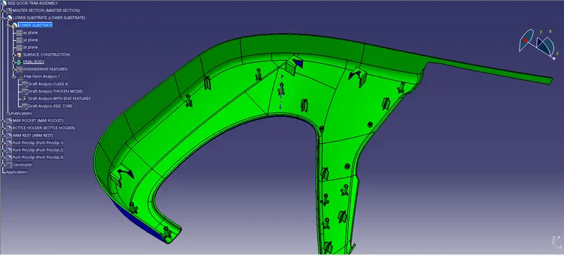
Draft analysis with side core axis:
Arm rest:
The same steps as followed to other components and the components as follows but the armrest wont clear so one more tooling axis is considered for the armrest.
The arm rest classA surface inspection:
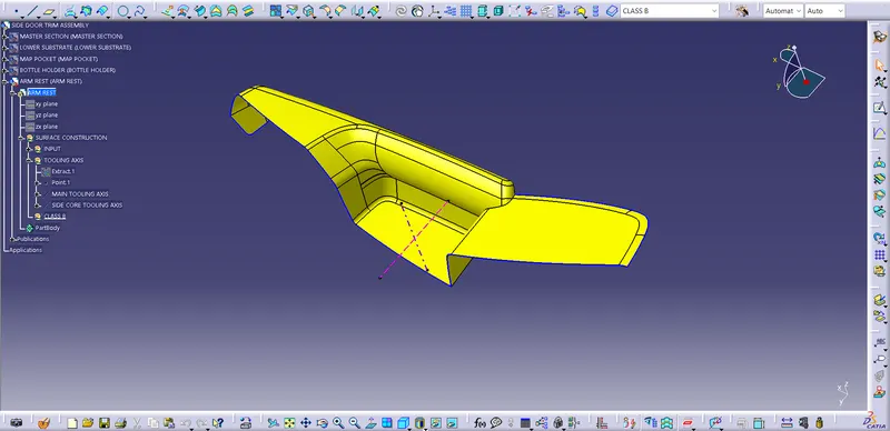
After completion of classB, ClassC and thick surface the thick body as follows:
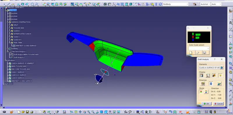
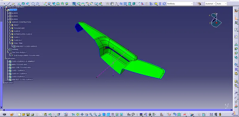
Close surface:
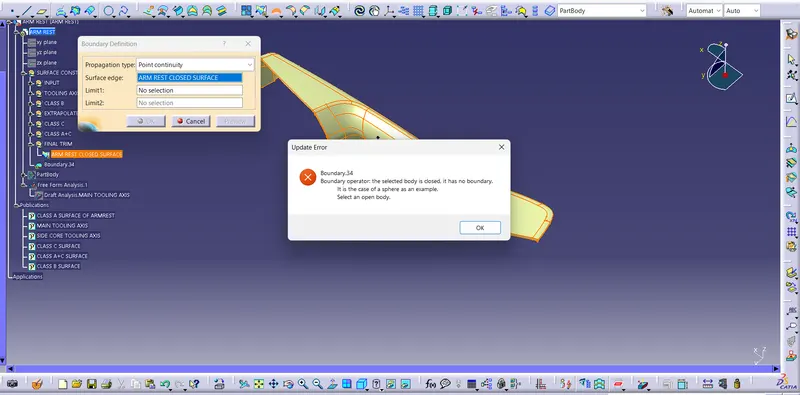
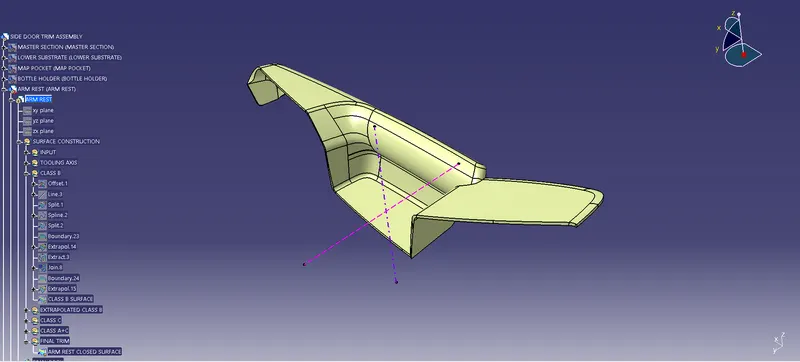
Thick surface draft analysis:
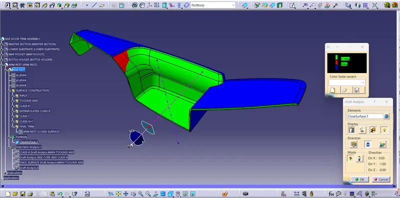
Arm rest with engineering features:
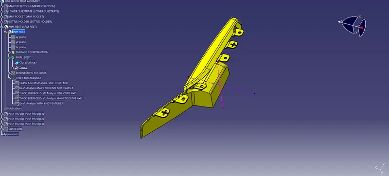
Draft analysis of with asembly tooling axis:
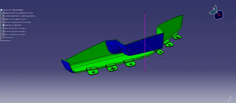
Map pocket:
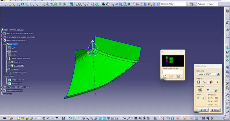
Inspection of classA surface and draft analysis of classA surface:
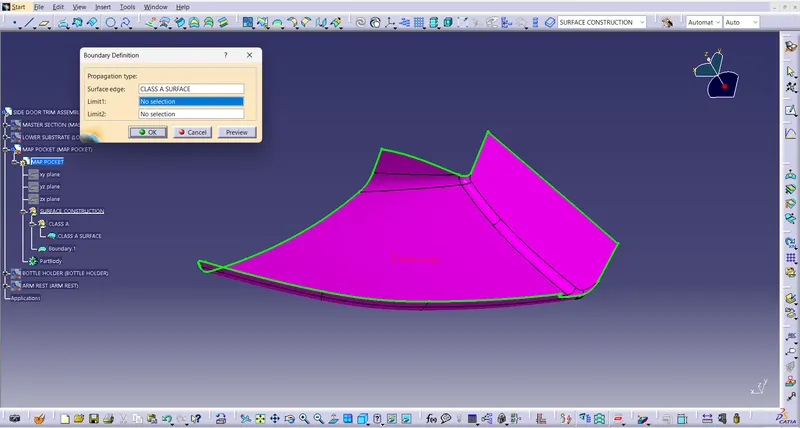
ClassB surface of map pocket:
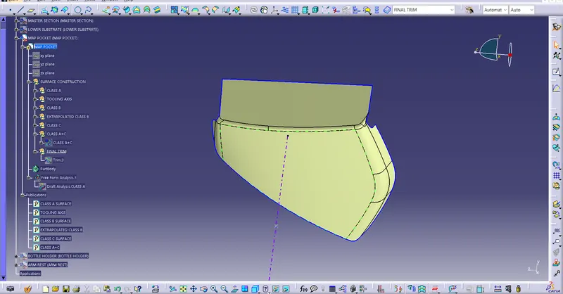
Class C
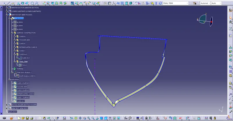
Close surface:
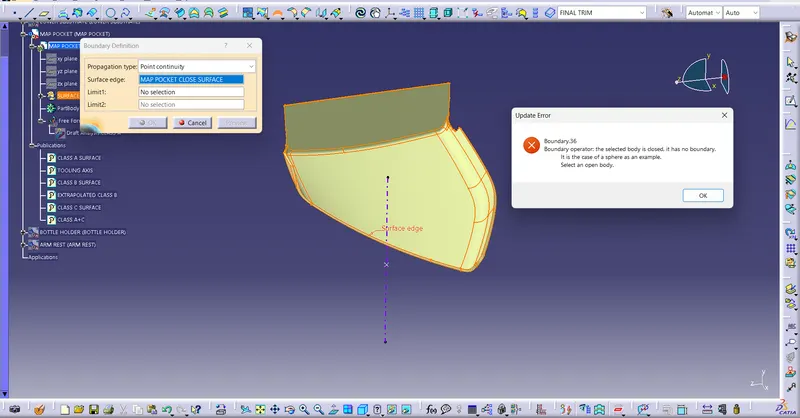
Thick surface and draft analysis of thick body:
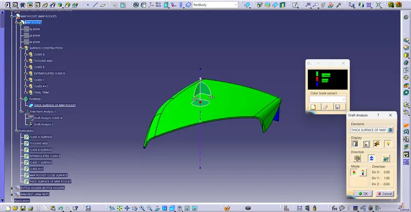
Final body with engineering features:
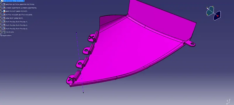
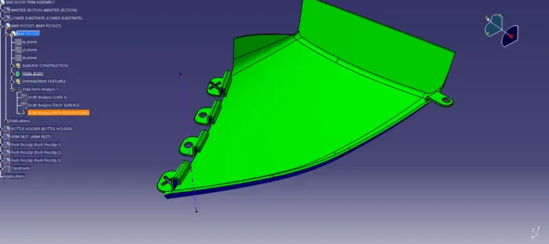
Draft analysis of final body with engineering features:
BOTTLE HOLDER:
Inspection & Draft analysis of classA surface
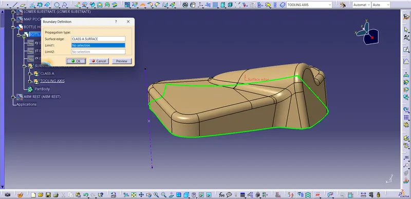
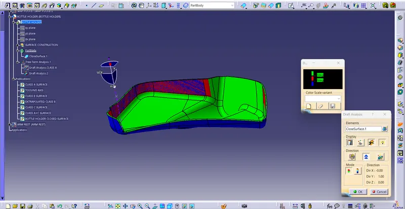
The class A is not cleared fully but cleared more than 90% of surface and created classB, classC
The class B & C Surface:
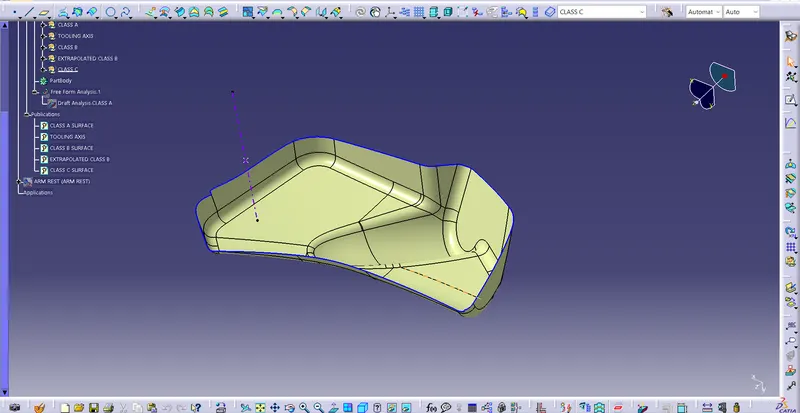
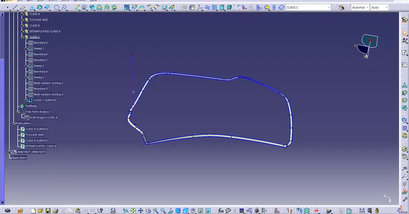
Inspection of closed surface
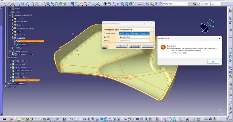
Thick surface and their draft analysis:
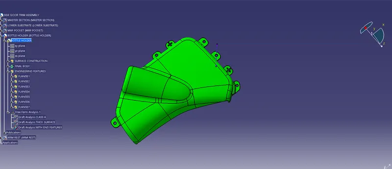
Final body with engineering features:
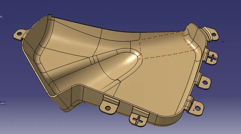
Draft analysis of final body:
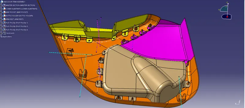
The total assembly of the above parts:
After completion of above assembly the push pin/clip is imported and assembled with final assembly and this follows and the push pin has 2 slots for height adjustment:
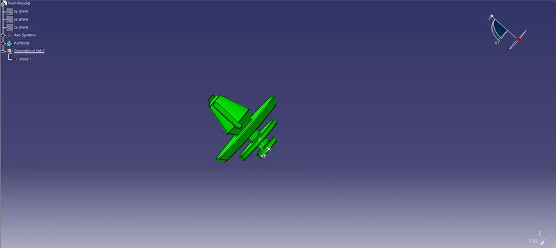
Final assembly with pushpin: