Week 11 - Project - A pillar Design with Master Section
AIM: Creation of A-Pillar Model by following the Master Section.
Taken the Thickness of the component to be 2.5 mm from the given master section.
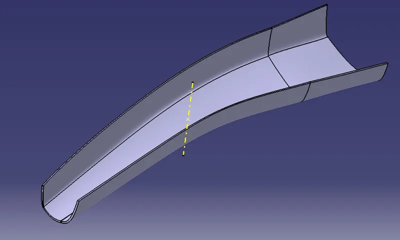
First, we need to check the given surface quality that is class A surface. Using boundary condition of operation tool bar check the continuity than have to check draft analysis.
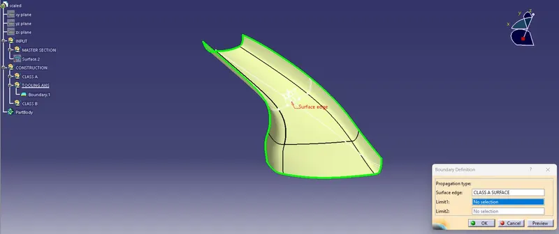
From above figure we can observe the surface showing 1 element which is outer boundary.
To create the tooling axis given master section is considered as reference in which the doghouse cross section. Actually, the outer walls of doghouse draft analysis is done through the main tooling axis. So, me used the outer walls of cross section and created the tooling axis using bisecting method.
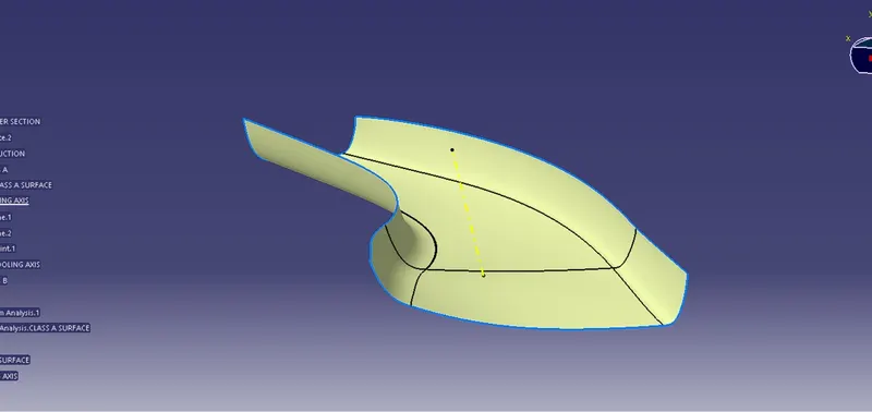
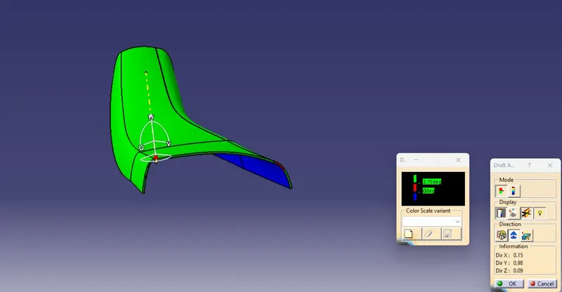
After creating tooling axis, the draft analysis of class A is as follows:
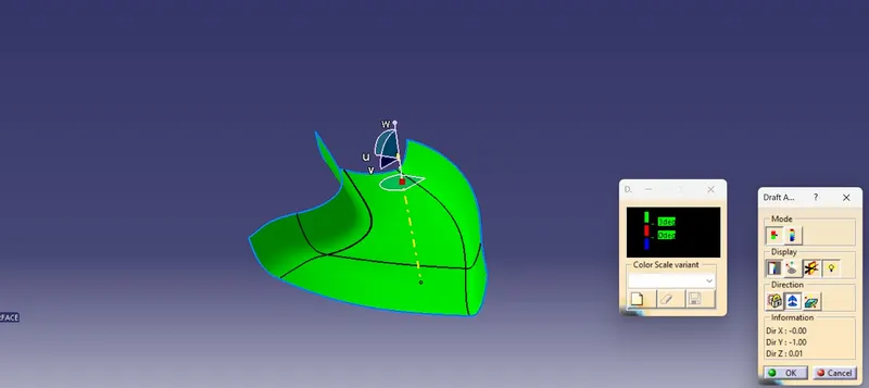
Draft analysis: The draft analysis technique is used to analyse whether our part model created in CAD is manufacturable based on the draft condition applied. Here the part should get easily removed from the panel dies or Mold (in case of plastic and sheet metal parts).
No parts can be ejected from the tool if it is having a straight 90-degree profile from its base surface. A small draft angle is provided to each and every area of the component in order to get easy removal of the component from the tool.
Here we are providing a direction in which components should eject in order to get easy removal of components from the tool. In other words, it also lets us know whether the model is having a draft angle and how much is the draft angle from the tool direction.
Using this command, the compass was set on the main tooling axis and the Draft angle was changed to 3 degrees.
Creating Class B Surface:
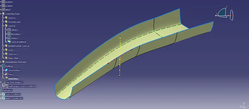
To create class B offset the class A surface of 2.5mm inside as per the given master section. After offsetting the class B created as follows:
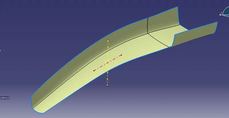
After creation of final classB all edges are extrapolated futher for the purpose of final trim.
Creating Class C Surface:
- The Class C surface connects the Class A and Class B surface.
- Initially the outline of the Class A surface was obtained using the Boundary
- In this model there is two types of class C surfaces are there one is parallel to the draft axis and another is perpendicular to the draft (tooling) axis.
The Sweep command was used along with draft direction, with a draft angle of 3 degree.
The final surface of Class C is created as follows:
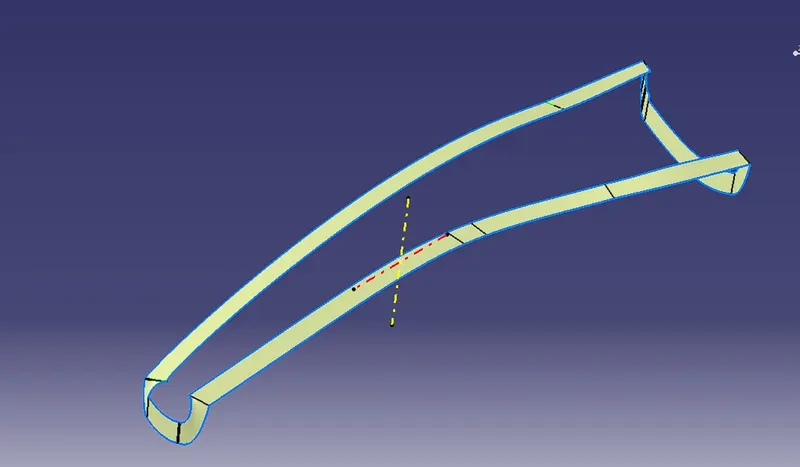
After creation of Class C, we need to join A&C. Finally, all the 3 surfaces were trimmed to form a closed surface. (A, B, C Surfaces). The final trim to form close surface.
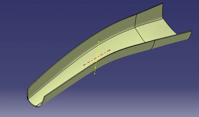
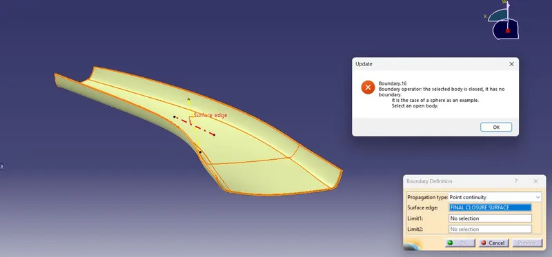
After forming the closer surface checking the surface with boundary option. Because of closer surface error will appear. Now we shift to the part work bench to add the thickness to the model.
After applying thickness to the close surface, the A-Pillar as follows:
The draft analysis of final sold body clearing for 2.75 degree 95% of surface and the result as follows:
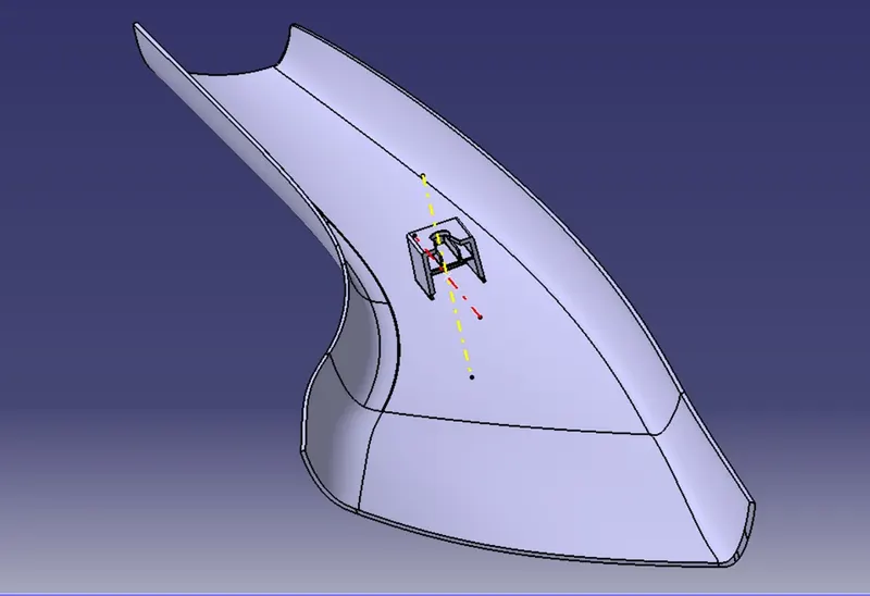
Adding Engineering features: (Dog house) from master section:
After the completion of above A-pillar now we started working on attachments as per the given Master section. These features created on the B-surface of the model side so we create all the details required for the features by extracting and projecting the given data to the B-Surface side. While creating doghouse one dog house created using Master section than copied to other side using translate tool with point to point consideration. The rotate the part with 180degree using center line which is created through point direction. After completion of creation of doghouse using master section the component looks as follows:
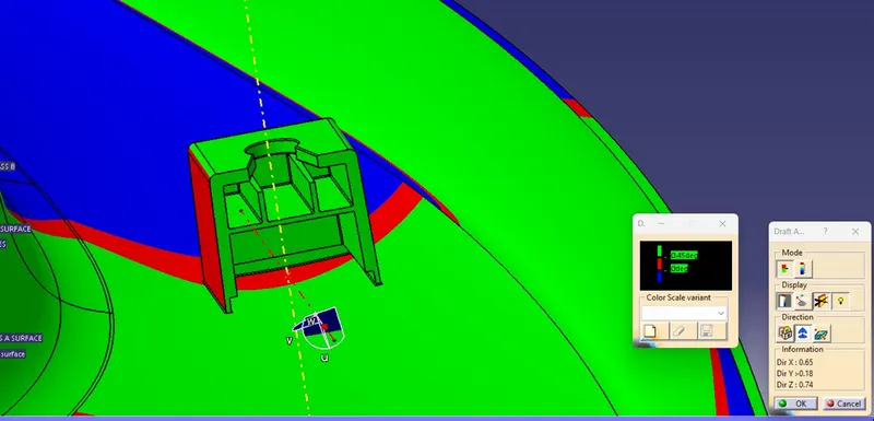
The draft analysis for the doghouse for 2 tooling axes as follows: In draft analysis if the doghouses are at different direction than we need to create different side core axis according to the doghouse direction. In this challenge me created doghouses are in same direction but with 180-degree angle difference so same side core axis is enough to know the draft clearance with invert selection.
With respective main tooling axis
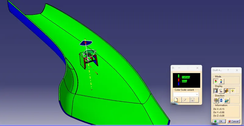
With respective side core tooling axis
Conclusion:
According to the above model the class A has defects in the shape. Due to this reason while creating class C and Creating Class B had some issues which are not by curvature has taken tangent continuity due to this at some places of class C failed in draft analysis. Finally dog house also created with given master section.