Advanced Sheet Metal Design Using NX Cad Challenge_5_Odd Shaped Enclosure
TITILE: odd shaped sheetmetal part
Objective:
The objective of this project is Converting Solid body into Sheet metal part.
INTRODUCTION
Sheet metal is a metal formed by an industrial process into thin, flat pieces. Sheet metal is one of the fundamental forms used in metalworking, and it can be cut and bent into a variety of shapes. Countless everyday objects are fabricated from sheet metal.
A sheet metal odd shaped part is selected for this project to understand the basics of Sheet metal application in Siemens NX. The odd shaped part has some important features like flange, beads, jogs etc. The odd shaped part is a basic component which can be used as a cover and other electronic components etc.
DESIGN METHODOLOGY
<!-- [if gte vml 1]> Creation Sketch Extrude SB Sheet metal from Solid SB Flange SB Jog Unbend Bead Sample Hole Rebend Flat Pattern Drafting
<![endif]>
<![endif]>
<![endif]>
<![endif]>
<![endif]>
<![endif]>
<![endif]>
<![endif]>
<![endif]>
<![endif]>
<![endif]>
<![endif]>
<![endif]>
<![endif]>
<![endif]>
<![endif]>
<![endif]>
<![endif]>
<![endif]>
<![endif]>
<![endif]>
<![endif]>
<!--[endif]--> 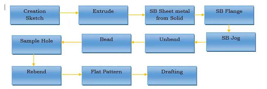
Description:
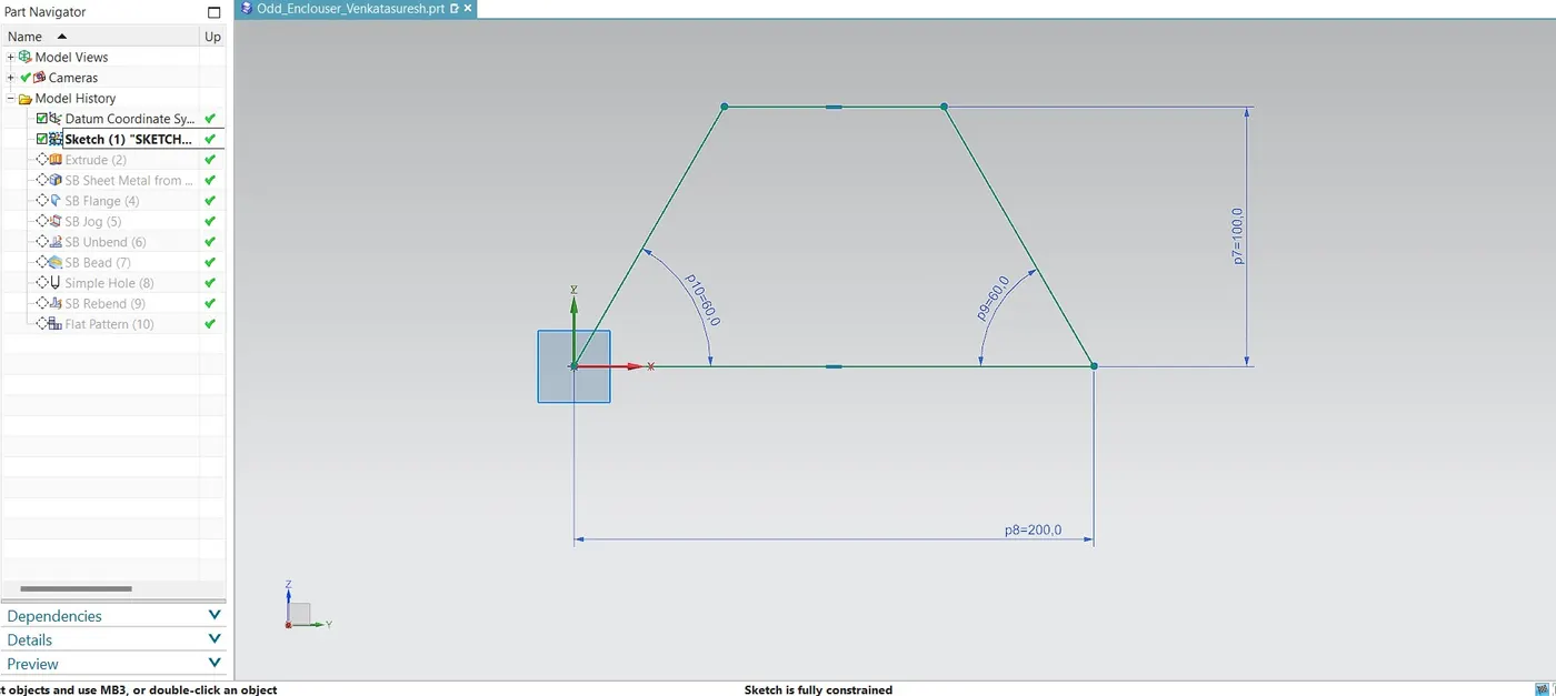
Creating the sketch with over all look of desired shape and the sketch as follows:
<!--[endif]-->
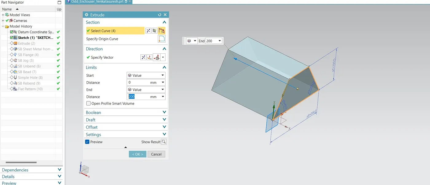
After creation of above sketch using extrude commond solid body is created as follows:
<!--[endif]-->
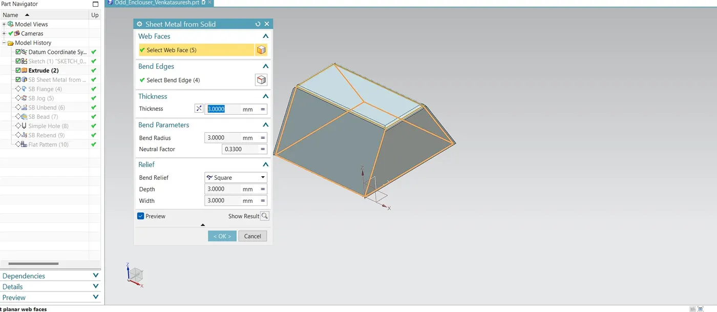
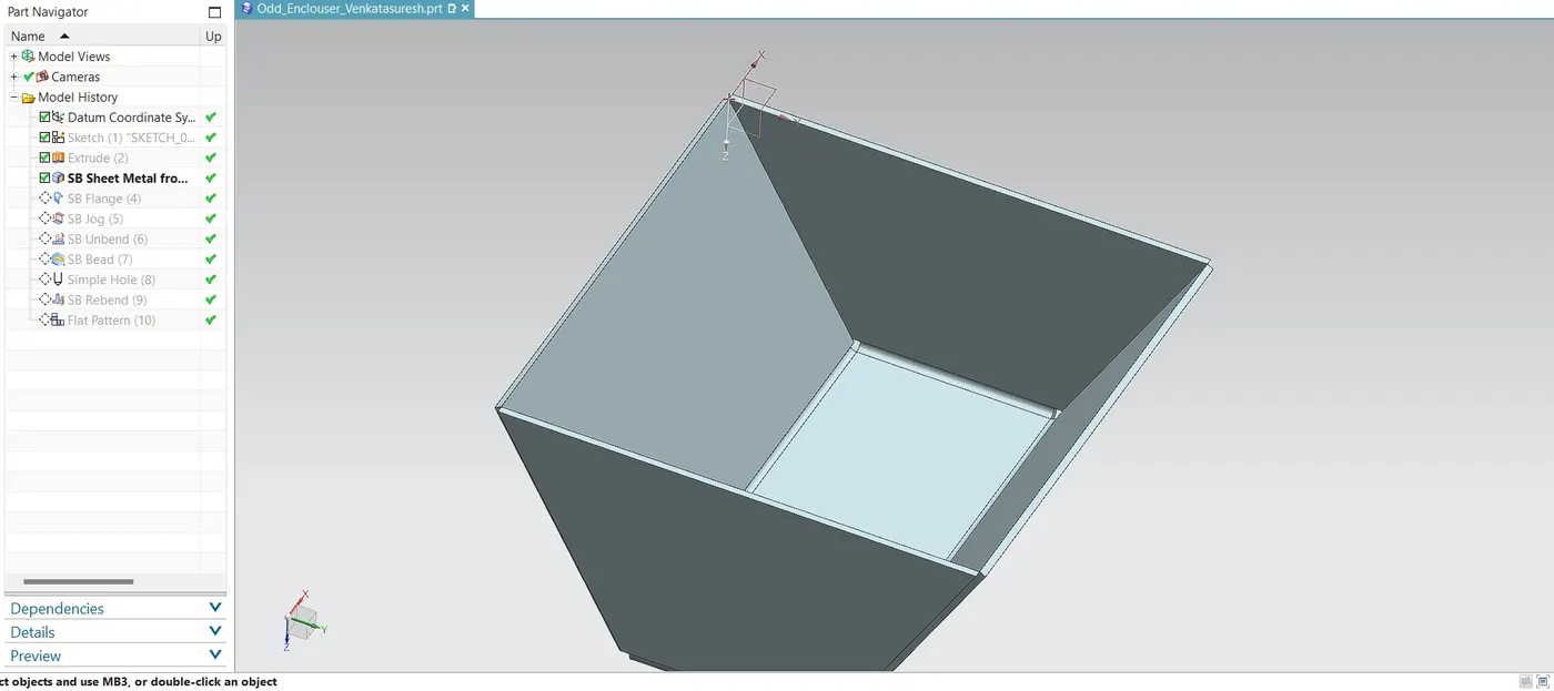
After creation of solid body to convert the solid to Sheetmetal, Sheet metal from sloid command is used and the web faces are selected and corresponding edges are selected as bend edges with thickness of 3mm and bend radius is 3mm.
<!--[endif]-->
From above operation the final product forms as follows:
<!--[endif]-->
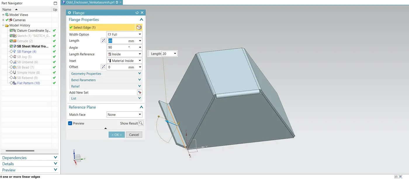
After above operation flange is created as follows:
<!--[endif]-->
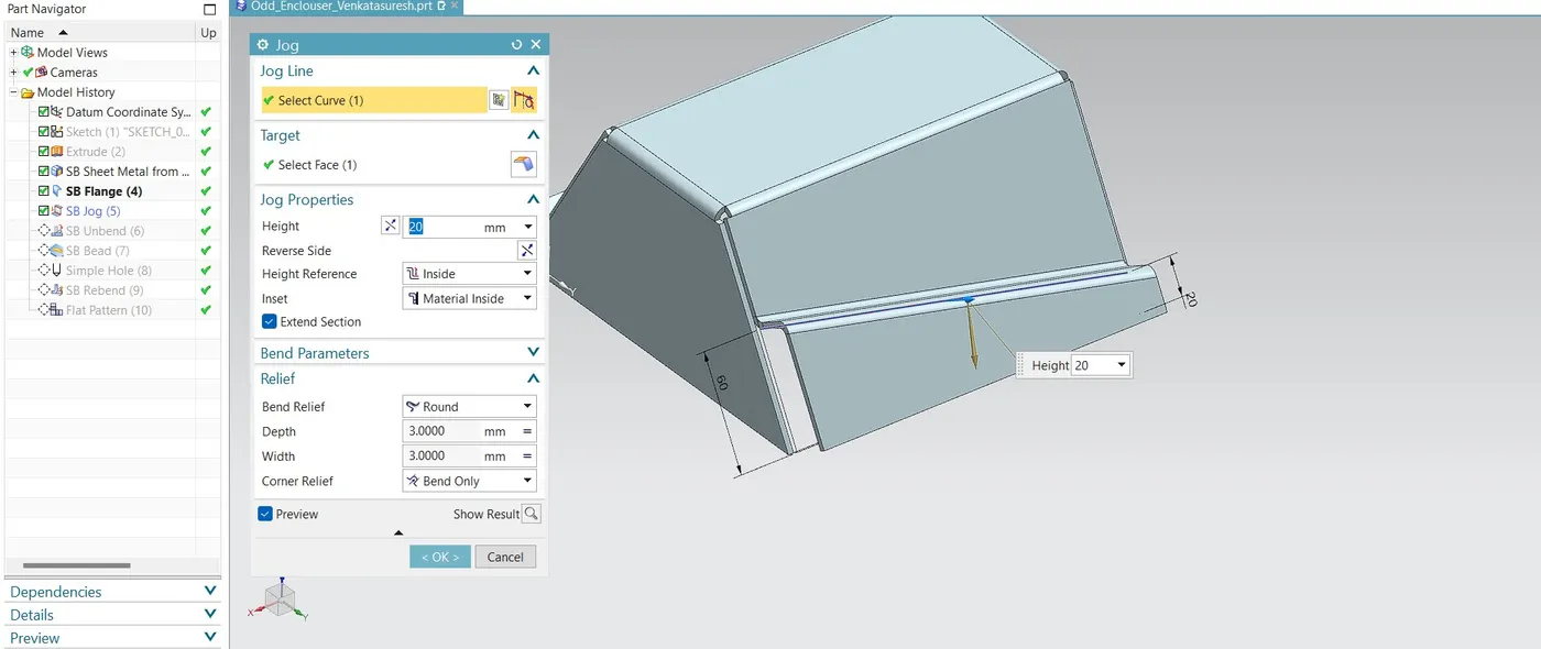
After completion of above operation one the other side of flange jog is created using jog command with slant curve on the face and the components as follows:
<!--[endif]-->
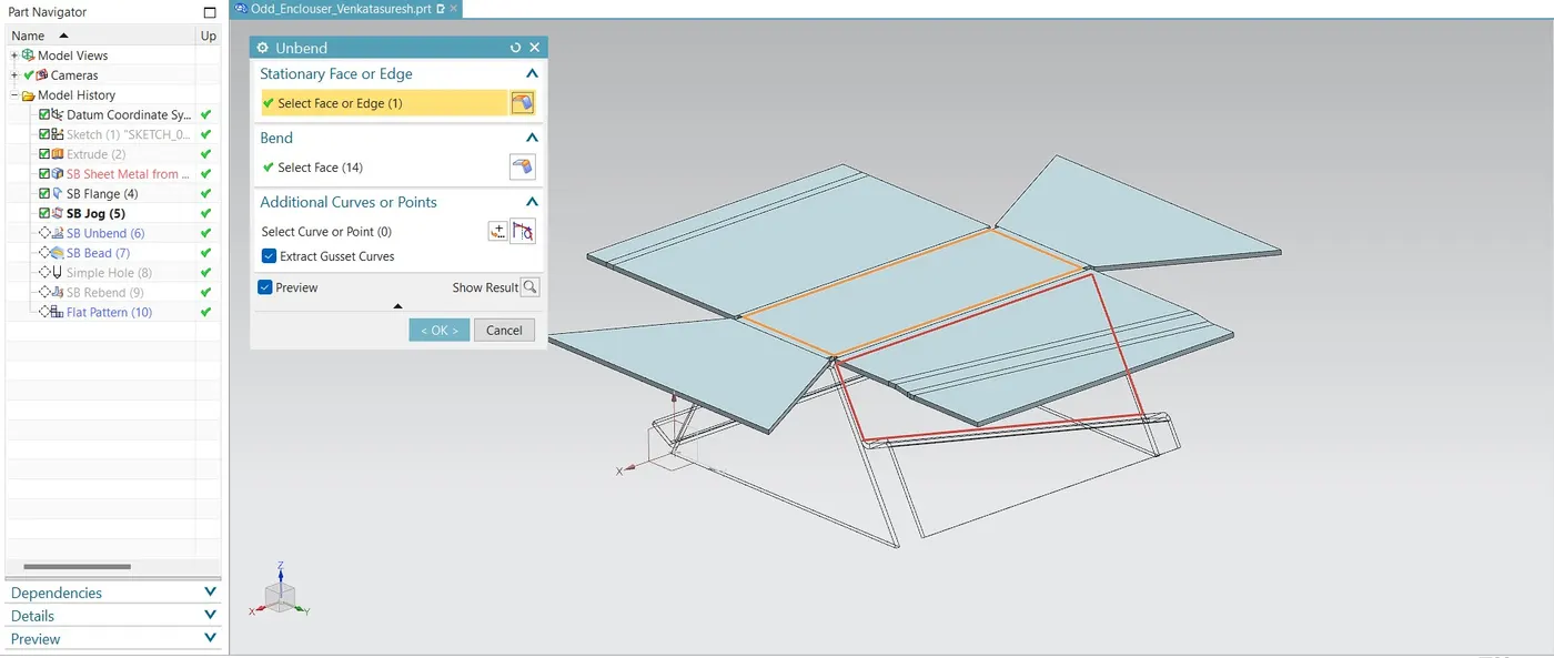
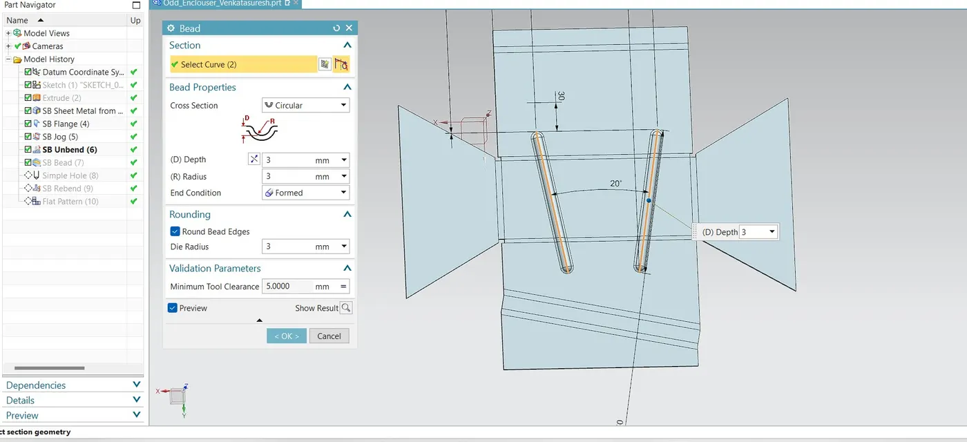
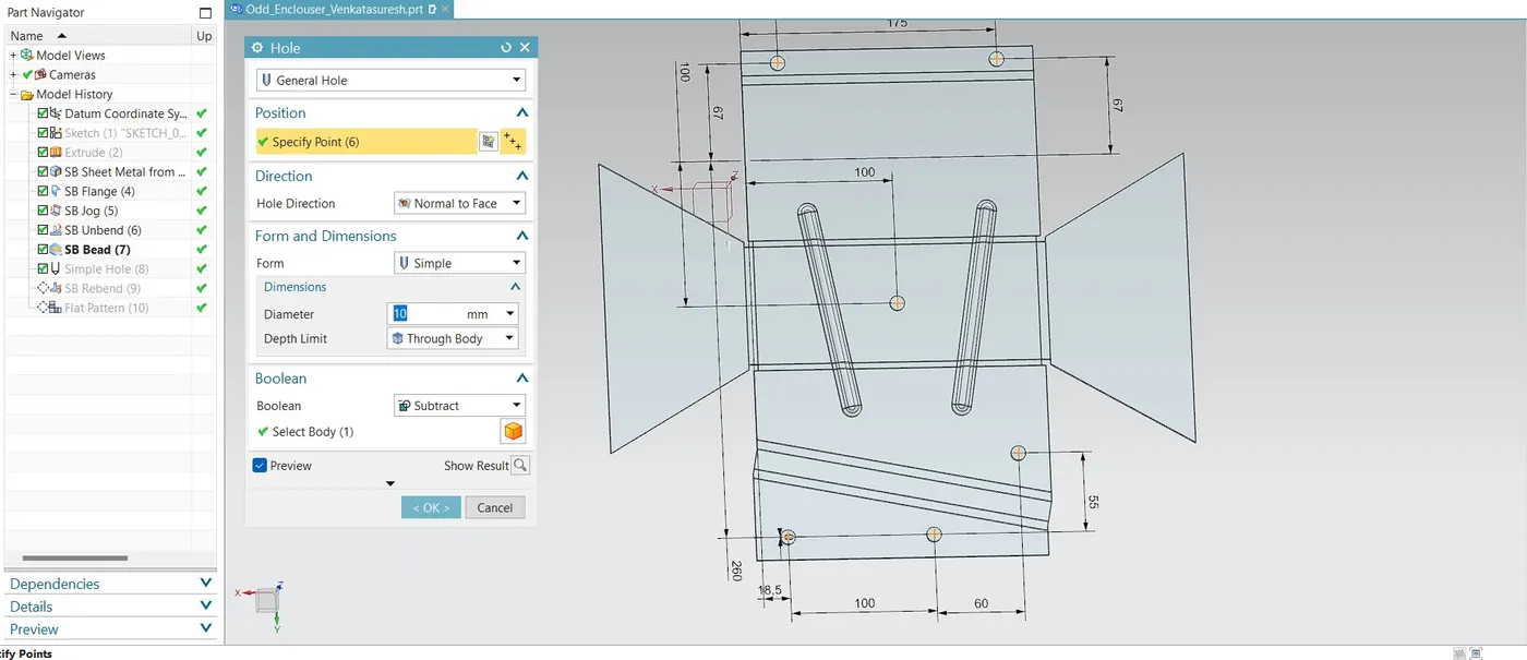
After above operation unbend command used to make beads and holes:
<!--[endif]-->
Bead is created as follows:
<!--[endif]-->
Holes are created as follows:
<!--[endif]-->
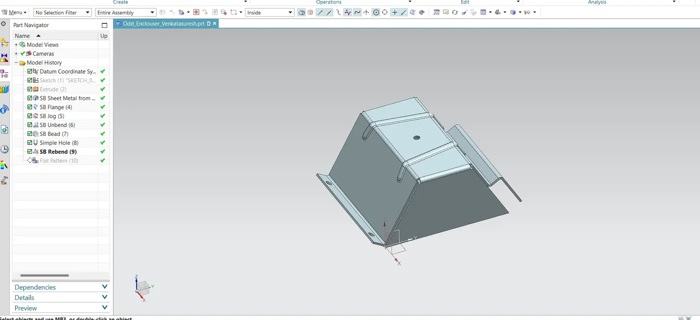
After completion of above operations rebend command is used & the final product as follows:
<!--[endif]-->
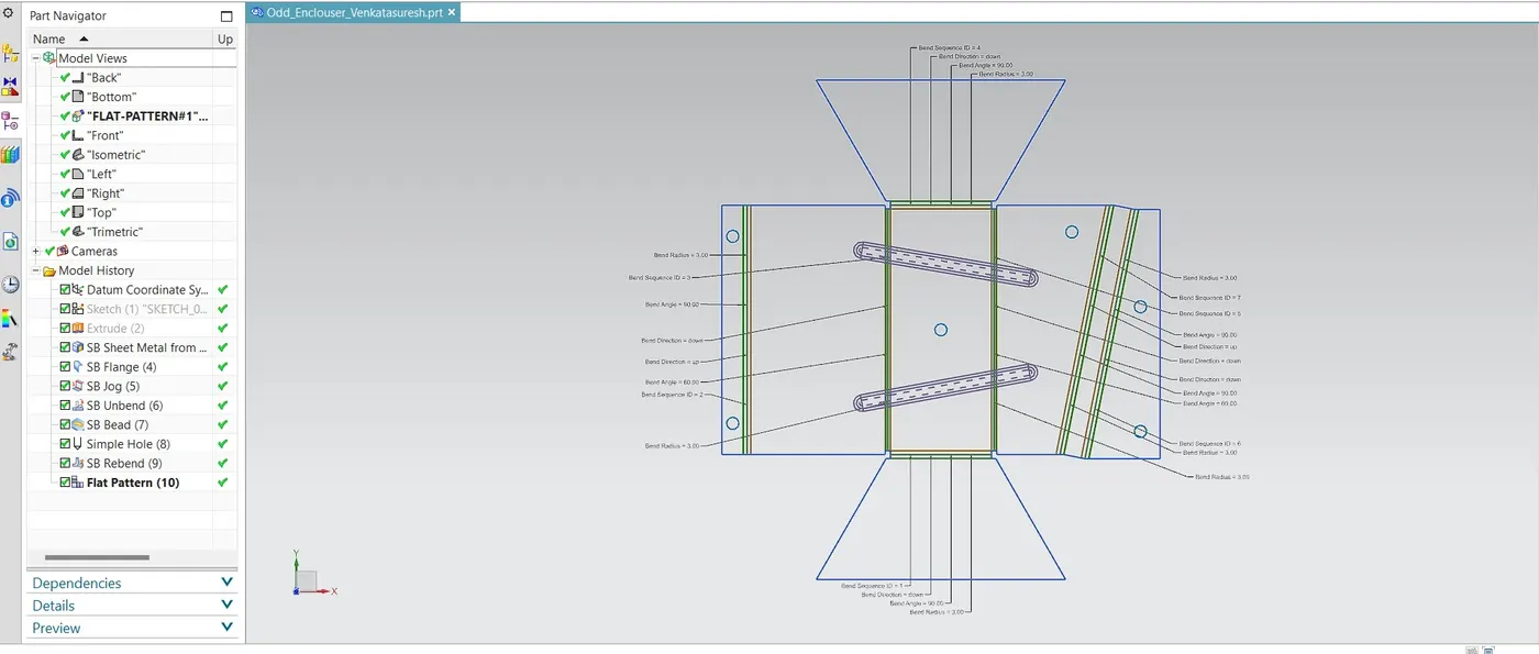
After completion of all operations flat pattern is used to create drafting and manufacturing drawings:
The flat pattern as follows:
<!--[endif]-->
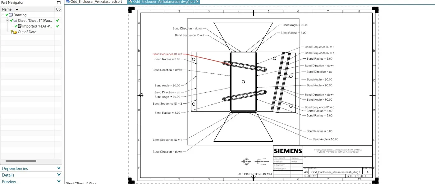
Using Drawing file drafting of flat pattern is created and the view as follows:
<!--[endif]-->
Conclusion:
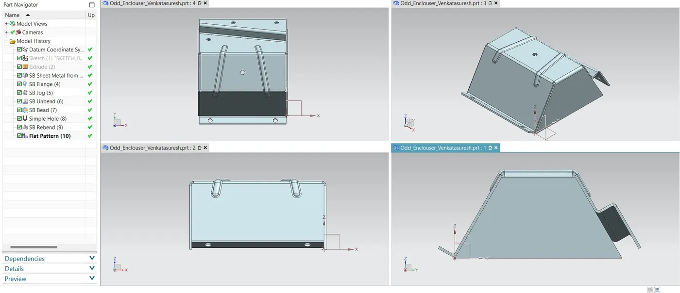
Finally, the odd shaped enclosure is created and drafted. The 4 views of final product as follows:
<!--[endif]-->