Wiring harness design in CATIA V5 - 3D modeling Week 4 Challenge
Q1. Route the following harness layout in Electrical workbench. Make assumption for harness bundle diameters. Use Following connectors as shown in layout diagram.
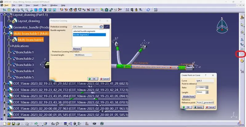
Add protective covering on all branches connected to DT06-2S & DT06-4S connectors. Keep end extremity at 30mm (from connectors end)
Download connector 3D data from www.te.com
- DT06-4S
- DT06-6S
- DT06-2S
- DT06-08SA
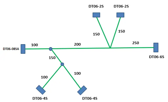
Answer:
4 Components downloaded from te.com. all components defined with electrical devices. All the given parts are connectors. In mechanical part design workbench Connector connection point, axis system, bundle connection point created for reference than shifted to electrical part design workbench where the components defined as electrical devices by electrical device definition tool bar. Than connecter connection point, Bundle connection point added to the component.
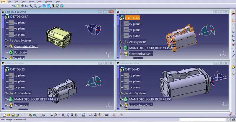
Later these components added to the connector catalogue library and imported to the Assy_Wiring_Harness_context file under Geometric bundle product. Before importing the connectors one layout drawing is created as per the given picture with the given dimensions.
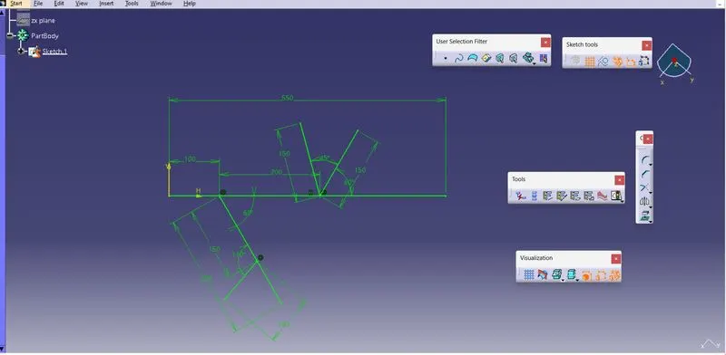
Connectors placed as per the layout drawing in mechanical part design assembly as below figure.
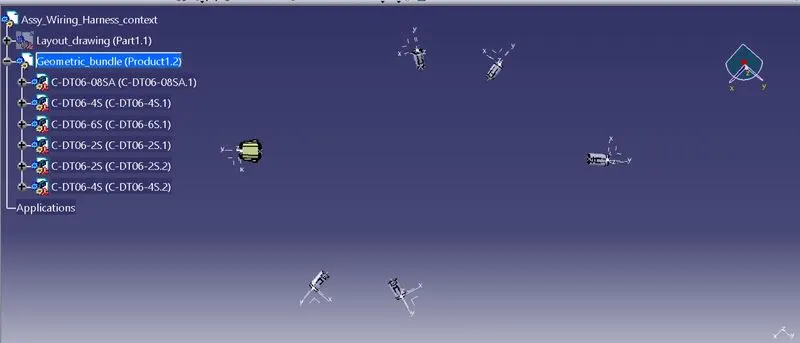
After above operation the workbench shifted to Electrical harness assembly where the assy wiring harness context added with geometric bundle properties.
After adding geometrical bundle properties, using multi-blanchable document tool the environment shifted to Electrical harness installation workbench.
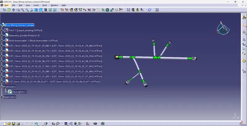
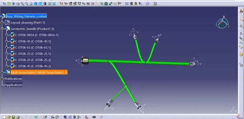
In Electrical harness installation workbench required wiring branches added between connectors and required branch points also added with add branch point tool. After completion of the above operations the assembly looks like the below figure.
Creating Wire Harness with Multi Branchable:
- Switch to Electrical harness Assembly Workbench.
- Select Multibranchable Document Icon.
- In the Branch Definition Box, describe all the required parameters like Diameter, Bend Radius (>=1.4), Build mode (slack, Length, Bend, Straight Bend).
- Click Route Definition and select the two components that you need to route.
- Click OK.
- Once the Multibranchable is created, Click Add branch point command and define the point on the main branch where the Harness Branch needs to be created.
- Repeat the steps.
- Add protective covering on the required branches by using Protective Covering Command and mention the start and end extremity points.
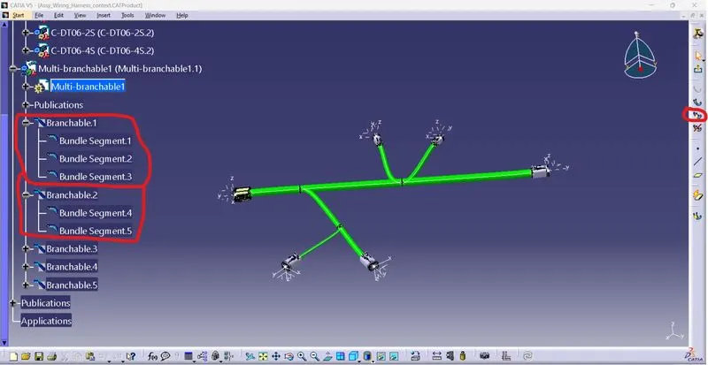
In the below figure given the details of branch bundle segments.
After completion of the above operation the protective covering added to the bundles with corrugated tube with start & end extremity.
The final product looks as follows.