Advanced Sheet Metal Design Using NX Cad Challenge_2_Box Assembly
SHEET METAL DESIGNING OF A BOX ASSEMBLY
OBJECTIVE
The objective of the project is to design a Box Assembly using sheet metal application in Siemens NX software.
INTRODUCTION
Sheet metal is a metal formed by an industrial process into thin, flat pieces. Sheet metal is one of the fundamental forms used in metalworking, and it can be cut and bent into a variety of shapes. Countless everyday objects are fabricated from sheet metal.
A sheet metal Box Assembly was selected for this project to understand the basics of Sheet metal application in Siemens NX. The box assembly has some important features like flange, dimple, normal cutouts etc. The box assembly is a basic component which can be used as a CPU cover and other electronic components etc.
DESIGN METHODOLOGY
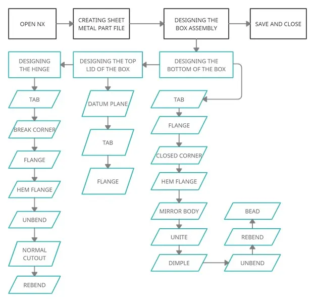
Description:
Design of Bottom Box of Box Assembly:
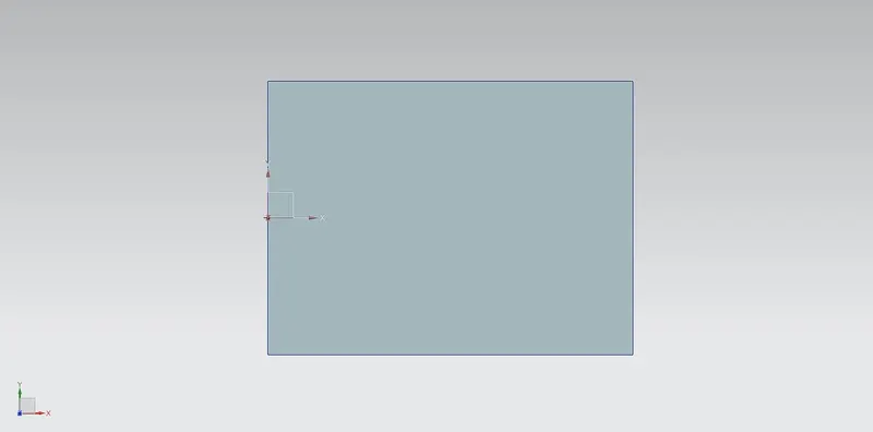
In bottom box creation first, we create sketch which is used to base using TAB
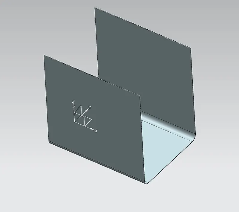
Creating Flanges using Flange commond :
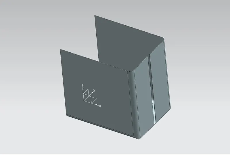
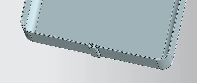
Hemflange is used to Modifies the model by folding the edge of a sheet metal flange over onto itself for the purpose of safe handling or to increase edge stiffness.
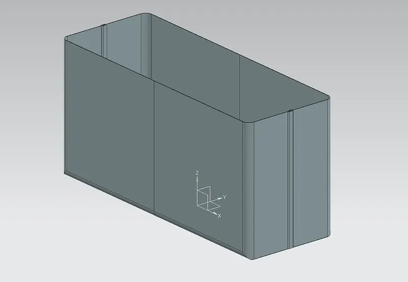
After above operation the entire body is mirrored using Mirror Body command the outlook as follows:
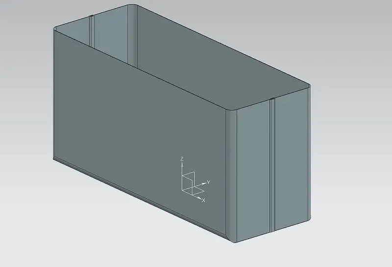
After Mirror Unite command is used to make as single body:
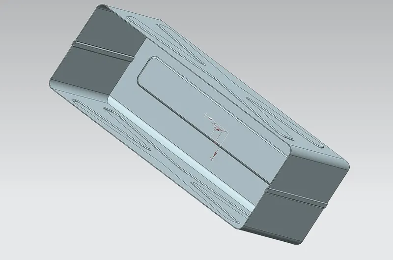
Dimple: after above operation to make component more stiff and strong side walls and bottom walls added with Embosses by using Dimple tool
Bead:
For lifting from the ground and attaching some rollers the beads are added 4 corners of box. One bead is created using bead tool other three are done by mirror tool.
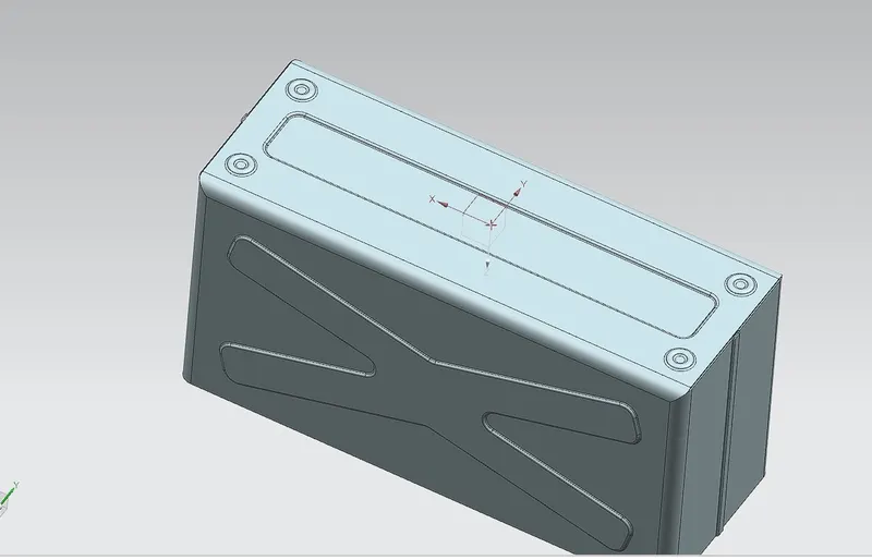
Hemflanges:
The hemflanges are added on the top edges of flanges to make box stiff and with stand of Lid of box weght and to remove sharp edges of the box and easy to handle the box from cutting the operater hands and body.
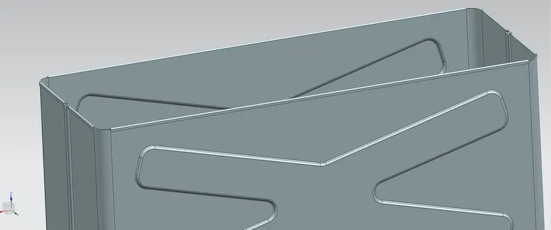
After all above operations flat pattern is created to fabricate the box and blank size calculation.
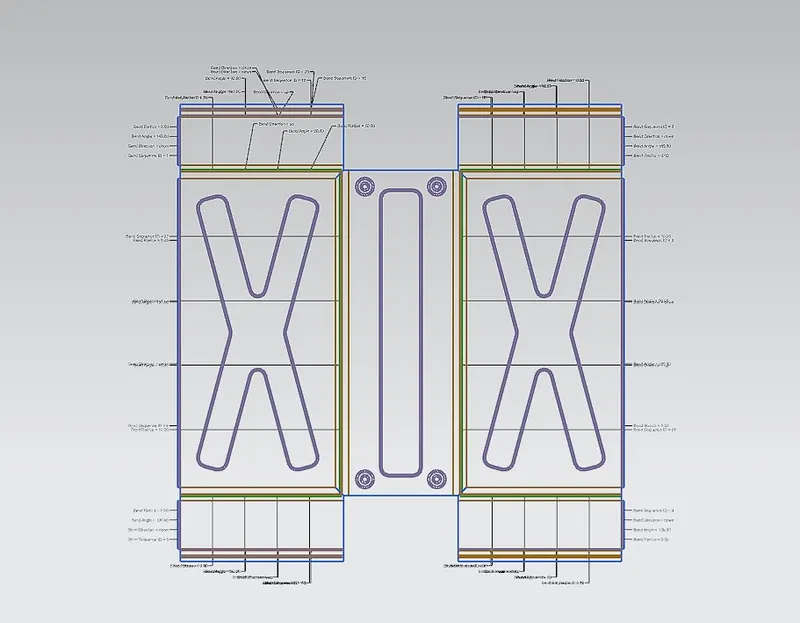
In the same way the Lid of the Box, Hinges are created using Tab, flange, Normal cut, Dimple operations. The flat patterns of the Lid, hinges as folllows :
Lid :
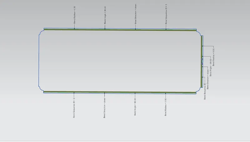
Lid Hing:
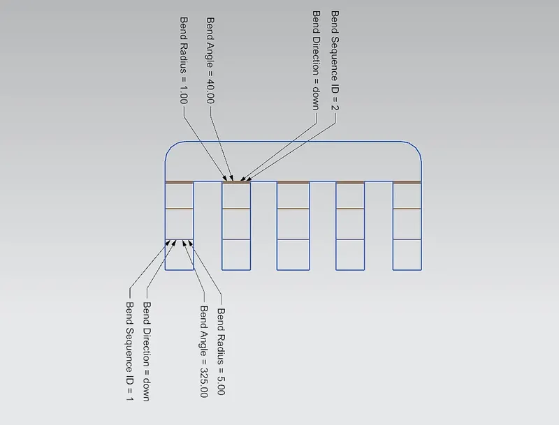
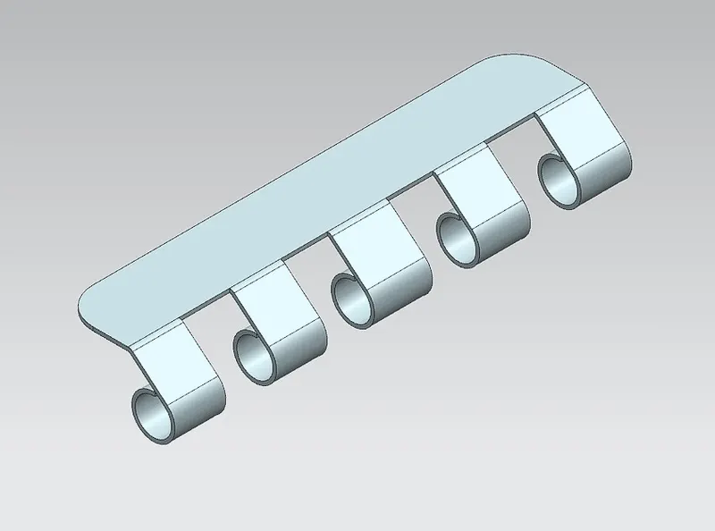
Box Hing:
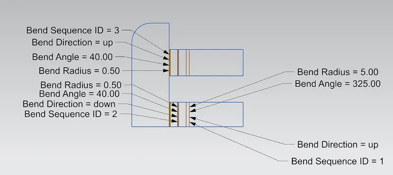
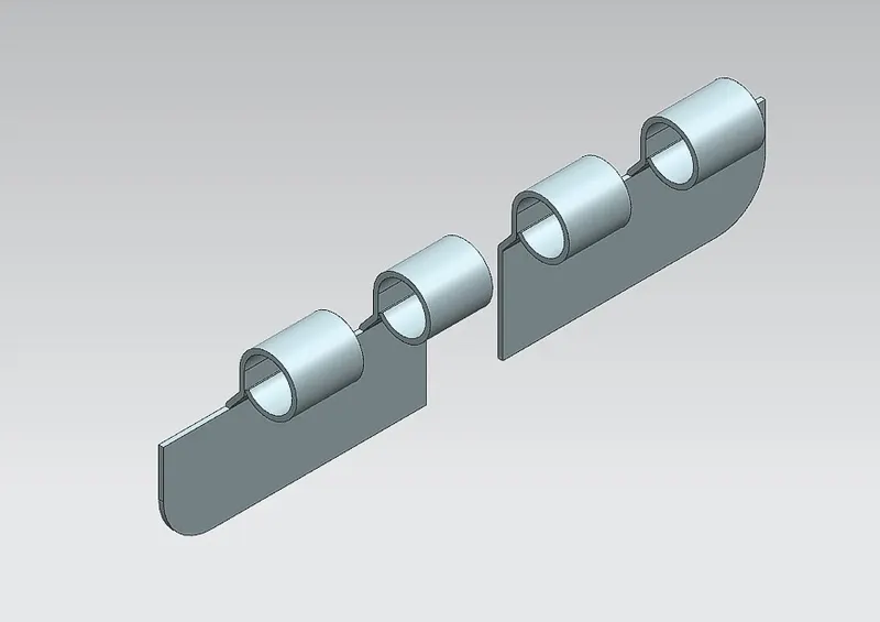
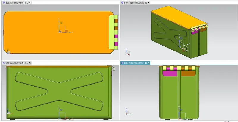
The final assembly as follows:
Drafting :
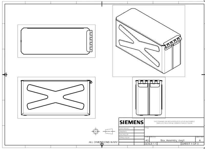
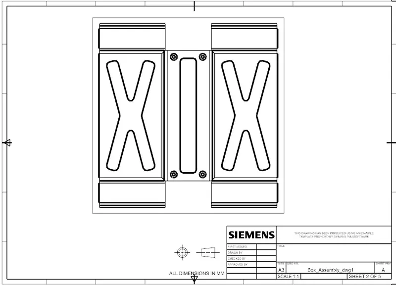
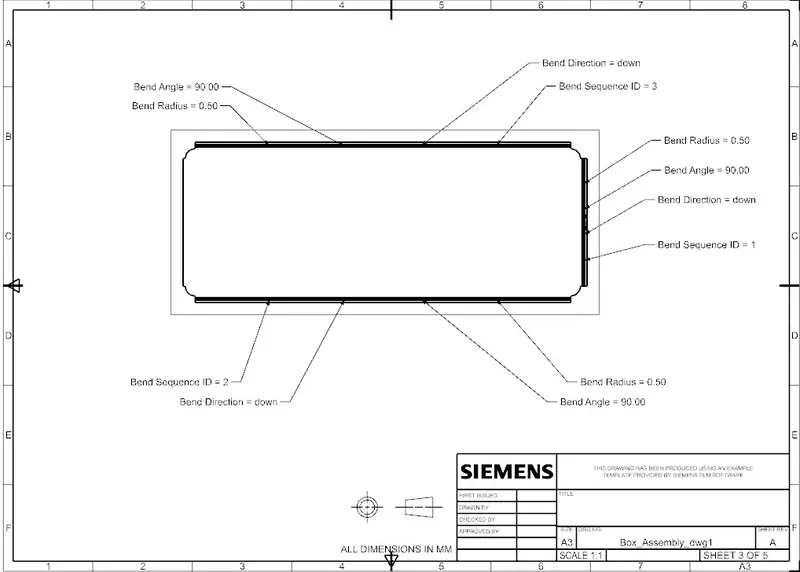
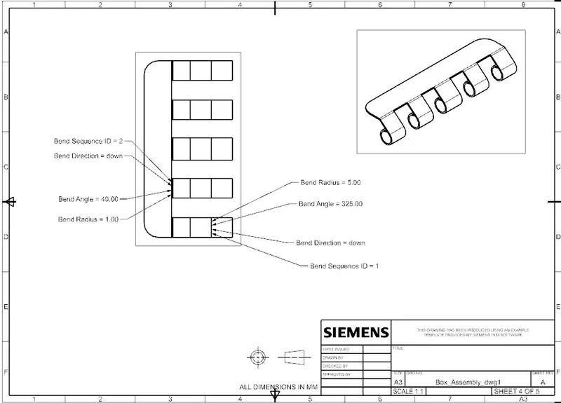
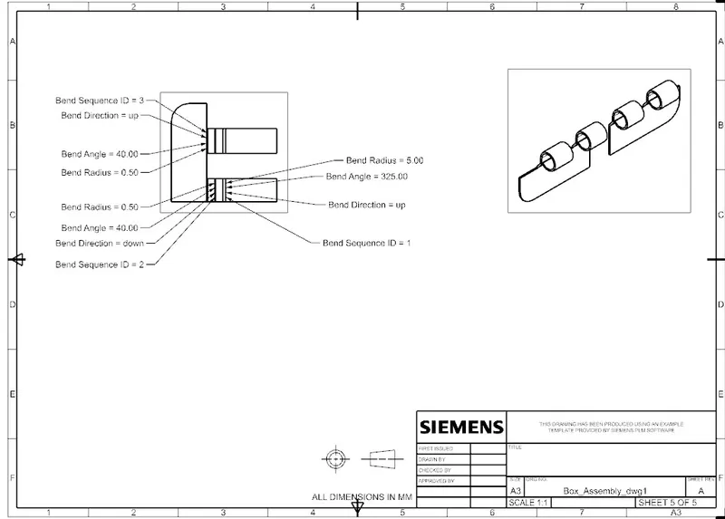
Conclusion : Asper the requirement of Box and Hing components are in 1mm sheet and Lid is in 2mm sheet is created as Box assembly.